Cable rescue apparatus and method
US20060231332A1
2006-10-19
11/109,275
2005-04-18
Abstract:
A high-rise building rescue system utilizing a single suspension cable and self-propelled gondola. The cable is peeled from the building side with a motorized vehicle and anchored at a pre-determined ground location. A support vehicle with an attached gondola is dispatched to the pre-determined ground location. The gondola is attached to the cable and moves to an upper floor of the high-rise building utilizing a cable traction mechanism.
Interested in similar patents?
Get notified when new applications in this technology area are published.
Classification:
A62B1/02 » CPC main
Devices for lowering persons from buildings or the like by making use of rescue cages, bags, or the like
B61B7/00 IPC
Rope railways ; Power and free systems
B61B7/00 IPC
Rope railway systems with suspended flexible tracks
Description
CROSS-REFERENCE TO RELATED APPLICATIONSThis application refers to the following USPTO applications submitted by the present inventor and which are incorporated herein by reference:
-
- a. application Ser. No. 10/456,126; Filed on Jun. 5, 2003; Titled “Peelable suspension cable positioning apparatus and method”
- b. application Ser. No. 10/777,555; Filed on Feb. 12, 2004; Titled “Cable traction apparatus and method”
Not Applicable
SEQUENCE LISTING OR PROGRAMNot Applicable
BACKGROUND OF THE INVENTIONThis invention relates to high-rise building fire fighting and rescue, specifically to an apparatus and method to enable a gondola to ascend from a ground location to an upper floor of a high-rise building. The gondola includes a traction mechanism to travel up a suspension cable.
The present invention has impact into two categories.
-
- a. The ability to carry a heavy load from a ground location to the upper floor of a high-rise facilitates fighting a fire.
- b. The ability to carry a heavy load from the upper floor of a high-rise to a ground location facilitates rescue of trapped people.
Examples of prior art and related limitations will be outlined.
U.S. Pat. No. 5,927,432, granted on Jul. 27, 1999 to Hershtik shows a rescue elevator arrangement that operates on the outside of a high-rise building. The limitations of this method include:
-
- a. The system operates only in a vertical arrangement. Many buildings include off-set rooflines.
- b. The anchor point is at the base of the building. This could be a dangerous location for emergency operations due to falling debris.
- c. The weighted cable is released from the building top in a gravity freefall. Windage could drift this cable on a tall high-rise thus causing difficulty for emergency personnel in locating the end.
- d. The attachment of the container to the vertical channel is not constrained. The alignment of this free connection of a large object could be difficult for emergency personnel.
- e. The aesthetics of the vertical channel running up the outside of the building could be objectionable.
U.S. Pat. No. 4,256,199, granted on Mar. 17, 1981 to Sellards shows a suspension cable arrangement with a container drive mechanism. The limitations of this method include:
-
- a. The anchor point to the high-rise building top is proposed as a grappeling hook. The ground anchor point is proposed as a fireplug or other solid object. These anchor methods could be too precarious and variable for safe emergency rescue.
- b. A single cable is proposed rather than a pilot cable leading to a suspension cable. The single cable approach limits the load carry capacity of the container.
- c. The cable handling method is too variable. At the building top, the grappling hook is free-released from a helicopter to the anchor position. At the base, the other cable end is again free-released. Ground personnel would then need to acquire the cable end. With variable weather conditions, these free-released connections could be too unpredictable for emergency response.
- d. There is no cable length adjustment. This could limit the load carry capability of the system. A longer cable is needed at mid suspension travel to lower the cable tensile forces. A shorter cable is needed at ground level to provide a higher vertical force component—thus allowing the gondola to lift from the ground. A shorter cable is also needed at the top of the high-rise building to allow the gondola end to contact the building as close to the upper floor as possible.
- e. There is no gondola cable transition support. This transition support adjusts the exit angles of the gondola traction mechanism to match the suspension cable. This reduces any transition bending and allows higher loads to be carried on a given cable size.
The object of the invention is to provide a safe rescue and fire fighting method for high-rise buildings that is operable under all conditions. The following preparations would be in place to for an operational system.
-
- a. A peelable pilot cable attached to the building side connected to a suspension cable spool on the building upper floor.
- b. A ground anchor attachment point a fixed distance from the building base.
- c. A chase vehicle to pull the pilot cable from the building base to the ground anchor location.
- d. A support vehicle which includes anchor attachment points, a cable winch and a trailer with a gondola. The gondola includes a cable traction mechanism.
The sequence of operation would be as follows:
-
- A. The high-rise building emergency alarm received.
- B. Chase vehicle dispatched to base of building and support vehicle dispatched to the related anchor location. The support vehicle includes a trailer with a gondola.
- C. Chase vehicle attaches to the pilot cable and moves to the anchor location—the pilot cable now suspends from the top of the high-rise building to the anchor location.
- D. The support vehicle is firmly attached to the anchor location.
- E. The pilot cable end is connected through the gondola traction mechanism to the support vehicle.
- F. The support vehicle retracts the pilot cable which is connected to the wound suspension cable on the top of the high-rise building.
- G. The pilot cable is completely wound and the suspension cable is properly tensioned between the building and the support vehicle.
- H. The gondola includes a cable traction system. This traction system causes the gondola to move up the suspension cable to the top of the high-rise building.
The advantages of the present invention include:
-
- a. Adaptable to all varieties of high-rise building architecture styles and off-set rooflines.
- b. No limit on overall building height.
- c. Completely under firefighter control.
- d. The high-rise building is passive—no use of electricity or access to an upper floor is required.
- e. Operable under all conditions—not affected by darkness, smoke, wind or snow.
- f. A base location for staging that is a safe distance away from the building.
- g. Provides rapid frefighter access and equipment transport.
- h. Provides rapid occupant evacuation including stretcher transport.
- i. A safe system that can be practiced by professional firefighter teams.
- j. Adjustable cable length to facilitate gondola movement and reduce total cable tensile stress at the cable mid-point.
- k. A gondola cable transition support to reduce cable strain and increase load carry capacity.
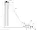
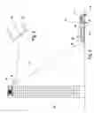
FIG. 1 is a side view of a building showing the building pilot cable.
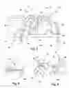
FIG. 2 is an enlarged view of the building spool from FIG. 1.
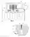
FIG. 3 is an enlarged view of the anchor footing from FIG. 1.
FIG. 4 is a side view of a building showing the chase vehicle.
FIG. 5 is a side view of a building showing the tractor, trailer and gondola.
FIG. 6 is an enlarged view of the suspension cable from FIG. 5.
FIG. 7 is an enlarged view of the tractor taken from FIG. 5.
FIG. 8 is an enlarged view of the chase vehicle taken from FIG. 5.
FIG. 9 is an enlarged view of the female connector taken from FIG. 8.
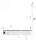
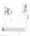
FIG. 10 is a side view of a building showing the suspension cable.
FIG. 11 is an enlarged view of the building spool taken from FIG. 10.
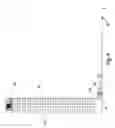
FIG. 12 is a side view of a building showing the gondola travel.
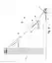
FIG. 13 is a side view of a skyscraper showing the gondola travel.
FIG. 14 is an enlarged side view of the gondola and traction apparatus taken from FIG. 5.
FIG. 15 is an enlarged side view of the gondola taken from FIG. 12.
FIG. 16 is an enlarged view of the cable roller taken from FIG. 15.
REFERENCE NUMERALS
| 20 building | 21 window | |
| 22 building spool | 23 building pilot cable | |
| 24 access box | 25 roadway | |
| 26 anchor footing | 27 spool yoke | |
| 28 yoke bolt | 29 building floor | |
| 30 friction block | 31 spool shaft | |
| 32 suspension cable | 33 cable adapter | |
| 34 earth | 35 anchor sleeve | |
| 36 anchor cover | 37 Belleville spring | |
| 38 chase vehicle | 39 gondola pilot cable | |
| 40 gondola | 41 tractor | |
| 42 winch bolt | 43 gear | |
| 44 bearing | 45 winch shaft | |
| 46 front anchor bolt | 47 rear anchor bolt | |
| 48 anchor block | 49 worm pinion | |
| 50 drive box | 51 female connector | |
| 52 male connector | 53 lever | |
| 54 trailer | 55 cable support | |
| 56 traction apparatus | 57 winch spool | |
| 58 bend lever | 59 bend lever cable | |
| 60 bend lever winch | 61 roller spring | |
| 62 skyscraper | 63 cable roller | |
| 64 angle cable | 65 angle cable winch | |
| 66 traction roller | 67 roller axle | |
| 68 bend lever axle | 69 stop block | |
| 70 traction pivot | 71 gondola operator console | |
| 72 gondola operator | 73 support operator console | |
| 74 support operator | 75 strain gage | |
| 76 spool bolt | ||
FIG. 1 is a side view of a building 20 showing the building pilot cable 23. The building 20 includes a plurality of windows 21. At the base of the building 20 is an access box 24 where one end of the building pilot cable 23 terminates. At the top of the building 20 is the building spool 22. A roadway 25 leads from the access box 24 to the anchor footings 26.
Applicant's co-pending application Ser. No. 10/456,126 further explains the apparatus and method of peeling the cable.
FIG. 2 is an enlarged view of the building spool 22 from FIG. 1. The spool yoke 27 is attached to the building floor 29 with yoke bolts 28. The building pilot cable 23 is routed over the radius surface of the spool yoke 27 and into the building 20. The building pilot cable 23 is attached to the cable adapter 33 which is attached to the suspension cable 32. The suspension cable 32 is coiled on the building spool 22. Pulling on the building pilot cable 23 causes the suspension cable 32 to unwind and thus rotate the building spool 22. The spool shaft 31 has a male threaded surface and is affixed to the spool yoke 27. The building spool 22 has a female threaded surface which mates with the spool shaft 31. As the building spool 22 rotates, the mating threaded surfaces cause the building spool 22 to lower onto the friction block 30. The friction block 30 is supported by the Belleville spring 37. As the suspension cable 32 is unwound, the Belleville spring 37 is gradually compressed. This provides suspension cable 32 tension that is proportional to the amount of cable unwound. The purpose of this mechanism is to provide a low resistive force for the initial unwinding of the suspension cable 32. This allows the chase vehicle 38 to pull the building pilot cable 23 out. As the chase vehicle 38 approaches the anchor footings 26, the extended suspension cable 32 causes substantial gravitational force. The friction block 30 prevents the cable from self-unwinding.
FIG. 3 is an enlarged view of the anchor footing 26 from FIG. 1. The anchor sleeve 35 includes an internal thread. The removable anchor cover 36 is used to keep debris out of the threaded area. The anchor footing 26 firmly affixes the anchor sleeve 35 to the earth 34. The upper surface of the anchor footing 26, anchor sleeve 35 and anchor cover 36 are flush with the roadway 25. This allows the anchor location to be placed where normal vehicular traffic moves. The anchor footing 26 material would be concrete. The anchor sleeve 35 and anchor cover 36 material would be steel. Alternate anchoring methods could include a hook and eye, U-bolt, earth anger or other standard fastening methods. Various materials could be used as needed for strength and installation requirements.
FIG. 4 is a side view of a building 20 showing the chase vehicle 38. The pilot cable 23 has been removed from the access box 24 and attached to the pilot vehicle 38. In the dotted view, the pilot vehicle 38 has then moved away from the building 20 and partially peeled the pilot cable 23.
FIG. 5 is a side view of a building 20 showing the tractor 41, trailer 54 and gondola 40. The chase vehicle 38 has traveled to the anchor location. The pilot cable 23 is now completely peeled from the building 30 side. The gondola 40 could be any variation of container with sufficient structure to support some method of traction apparatus and carry an emergency load.
FIG. 6 is an enlarged view of the suspension cable 32 from FIG. 5. The suspension cable 32 has begun to unwind from the building spool 22. The cable adaptor 33 between the pilot cable 23 and the suspension cable 32 is now suspended.
The pilot cable 23 and gondola pilot cable 39 would be stranded steel approximately ⅝ inch diameter. The suspension cable 32 would be stranded steel approximately 2 inch diameter. The pilot cable 23 must be light and flexible to allow manual emergency personnel positioning. The pilot cable 23 must also be strong enough to support the deployment of the suspension cable 32. The pilot and suspension cables could be made of alternate materials and sizes that provide the needed flexibility and strength.
FIG. 7 is an enlarged view of the tractor 41 taken from FIG. 5. The tractor 41 is shown at the anchor location. The front anchor bolt 46 is shown in the travel position. The rear anchor bolt 47 is shown in the anchored position. Emergency personnel would position the front anchor bolt 46 over the anchor sleeve 35 and use a pneumatic driver to rotate the front anchor bolt 46. The gondola pilot cable 39 is attached to the winch spool 57 via winch bolt 42. The winch spool 57 is attached to the winch shaft 45 and rotates on bearing 44. The gear 43 is attached to the winch spool 57. The drive box 50 rotates the worm pinion 49 which engages the gear 43 and causes rotation of the winch spool 57. A support operator 74 would control the winch spool 57 via the support operator console 73.
FIG. 8 is an enlarged view of the chase vehicle 38 taken from FIG. 5. Note the gondola pilot cable 39 exiting out the rear of the gondola 40. The excess gondola pilot cable 39 and male connector 52 would be removably attached to the gondola 40 during transport. The male connector 52 is shown detached from the gondola 40 and ready to be attached to the building pilot cable 23. The movement of the male connector 52 to the building pilot cable 23 would be completed by a rescue person.
FIG. 9 is an enlarged view of the female connector 51 taken from FIG. 8. The end of the building pilot cable 23 is attached to the female connector 51. The male connector 52 is shown being snap fit inserted into the female connector 51. Referring again to FIG. 8—after this snap fit insertion, the lever 53 is moved clockwise 90 degrees to release the female connector 51 from the chase vehicle 38.
The female connector 51 is smaller in diameter than the suspension cable 32. This allows the female connector 51 to freely pass thru the traction apparatus 56. The traction apparatus 56 would be energized to facilitate the suspension cable 32 passing through the device.
FIG. 10 is a side view of a building 20 showing the suspension cable 32. The chase vehicle 38 has moved away from the rear of the gondola 40. The building pilot cable 23 has been completely wound on the winch spool 57 resulting in the suspension cable 32 suspending from the building spool 22 to the winch spool 57. The suspension cable 32 has been properly tightened and the gondola 40 is ready to move up the suspension cable 32.
All of the figures are drawn with cables as straight lines. In actual practice, gravitational force due to the cable mass would cause a centenary curve. How much the centenary curve deviates from a straight line is a function of the cable length. By increasing cable length and allowing more catenary curve, the cable tension is reduced. In theory, the extreme case of a straight line cable would require an infinitely high cable tension.
During gondola 40 lift-off as shown in FIG. 10, the suspension cable 32 would be shortened. This shorter suspension cable 32 would provide a higher vertical cable tension component. The vertical tension component would need to be higher than the gondola 40 weight. With an excessively long suspension cable 32 length, the gondola 40 would drag horizontally off the trailer 54 rather than lift-off.
FIG. 11 is an enlarged view of the building spool 22 taken from FIG. 10. The upper end of the suspension cable 32 is securely affixed to the building spool 22 with the spool bolt 76. The building spool 22 has now moved down the threads of the spool shaft 31. The Belleville springs 37 are now fully compressed.
FIG. 12 is a side view of a building 20 showing the gondola 40 travel. The gondola 40 has moved partially up the suspension cable 32. The dotted view shows the gondola 40 aligned with an upper floor of the building 20. The suspension cable 32 length would be shortened to facilitate the gondola 40 meeting the building 20 at as high a floor as possible. Note that for drawing demonstration purposes, the building 20 is shown with less than 20 stories.
FIG. 13 is a side view of a skyscraper 62 showing the gondola 40 travel. The skyscraper 62 in FIG. 13 is shown with 50 stories. The gondola 40 is at the mid-point of the suspension cable 32 span. At this position of the gondola 40, the suspension cable 32 tension is at a maximum due to the gondola 40 weight. It is important to have a longer suspension cable 32 at this moment to keep the suspension cable 32 tension within a safe limit. In practice the suspension cable 32 length is:
-
- a. shortened for lift-off
- b. gradually lengthened on the travel from lift-off to mid-point
- c. gradually shortened on the travel from mid-point to docking at the upper floor of the skyscaper 62
All of the various cable connections are non-detaching. Non-detaching means that the connection positions are constrained. Examples of these constrained connections include:
-
- a. suspension cable 32 upper end pre-attached to the upper floor of the building 20—see FIG. 11
- b. suspension cable 32 pre-attached to the building pilot cable 23 upper end—see FIG. 6
- c. building pilot cable 23 lower end pre-attached to the access box 24—see FIG. 4
- d. emergency personnel manually positioning the female connector 51 from the access box 24 to the chase vehicle 38—see FIG. 4
- e. moving the chase vehicle 38 to the anchor footing 26 location with the female connector 51 attached—see FIG. 8
- f. gondola pilot cable 34 pre-attached to the winch spool 57—see FIG. 7
- g. gondola pilot cable 39 pre-positioned through the traction apparatus 56 and plurality of cable rollers 63—see FIG. 14
- h. emergency personnel manually positioning the male connector 52 from the gondola 40 into the female connector 51.
After the female connector 51 is released from the chase vehicle 38, the cable path is completed. During the entire process, there were no loose connections that had to be located.
FIG. 14 is an enlarged side view of the gondola 40 and traction apparatus 56 taken from FIG. 5. A further refinement of the suspension, cable 32 length adjustment would be to also monitor suspension cable 32 tension. This would be accomplished with strain gages 75 installed at the spool bearing mounts 44. The strain gages 75 would be positioned and calibrated to correlate with suspension cable 32 tension.
With constant suspension cable 32 tension monitoring, the suspension cable 32 length could be adjusted as needed. At the gondola 40 travel mid-point as shown in FIG. 13, depending on the gondola 40 load, the suspension cable 32 could be lengthened only as needed. The tension monitoring would allow larger loads to be safely carried on the gondola 40. Also, each building 20 may have a safe load limit for suspension cable 32 tension. Tension monitoring would facilitate staying within this building 20 load limit. Note the traction pilot cable 39 passing through the traction mechanism 56 and under the plurality of cable rollers 63.
Applicant's co-pending application Ser. No. 10/777,555 further explains the apparatus and method of the traction device.
FIG. 15 is an enlarged side view of the gondola 40 taken from FIG. 12. The bend lever 58 is attached to the end of the roller spring 61. The bend lever 58 rotates about the bend lever axle 68 to a storage position for transport of the trailer 54 on city roads. FIG. 14 shows the bend lever 58 in the stored position. FIG. 15 shows the bend lever 58 against the stop block 69 and ready for operation.
It is desirable to evenly spread the gondola 40 weight over a long length of suspension cable 32. The multiple cable rollers 63 on the roller spring 61 accomplish this. One end of the roller spring 61 is firmly affixed to the traction mechanism 56. The roller spring 61 is a flexible member made of a material such as spring steel. The traction roller 66 operates similar to the cable roller 63.
It is also desirable to have cable support adjustment which would cause the suspension cable 32 to enter and exit the traction apparatus 56 tangentially. Any abrupt angle change could weaken the suspension cable 32. The suspension cable 32 entry and exit angles are controlled with adjusting the length of the bend lever cable 59 via the bend lever winch 60. To keep the gondola 40 level, the angle cable 64 is adjusted via the angle cable winch 65. The traction apparatus 56 rotates relative to the gondola 40 on the traction pivot 70. A gondola operator 72 would control the gondola 40 via the gondola operator console 71.
To maintain the maximum suspension cable 32 strength, it is important for the traction apparatus 56 to be linear. Linear means that the suspension cable 32 moves through the traction apparatus 56 in a straight line without bending.
FIG. 16 is an enlarged view of the cable roller 63 taken from FIG. 15. A portion of the gondola 40 weight is supported by each cable roller 63. The cable roller 63 rotates on the roller axle 67 which is affixed to the roller spring 61. The perimeter of the cable roller 63 has a concave surface to match the suspension cable 32 diameter.
In any event, the invention is only intended to be limited by the scope of the following claims.
Claims
I claim:1. A transport system comprising:
a. a container with means for causing traction;
b. a base location with means for anchoring;
c. means for suspending a cable from an elevated location through said means for causing traction to said base location;
d. wherein said means for causing traction moves said container up said cable.
2. A transport system as defined by claim 1 wherein said means for suspending a cable is non-detaching.
3. A transport system as defined by claim 1 wherein said means for causing traction is linear.
4. A transport system as defined by claim 1 wherein said means for suspending a cable includes a pilot cable and a suspension cable.
5. A transport system as defined by claim 1 wherein said means for anchoring includes a street ground anchor.
6. A transport system as defined by claim 1 wherein said means for suspending a cable includes means for adjusting said cable length.
7. A transport system as defined by claim 6 wherein said means for adjusting said cable length includes sensing of said cable tension.
8. A transport system as defined by claim 1 wherein said container includes cable support adjustment.
9. A transport system as defined by claim 1 wherein said elevated location includes a building spool brake.
10. A transport system comprising:
a. a base location;
b. an elevated location;
c. a cable suspended from said elevated location to said base location;
d. a container;
e. a vehicle for moving said container to said base location;
f. a traction apparatus for moving said container up said cable.
11. A transport system as defined by claim 9 wherein said cable is non-detaching.
12. A transport system as defined by claim 9 further including means for adjusting said cable length.
13. A transport system as defined by claim 9 wherein said container includes cable support adjustment.
14. A transport system as defined by claim 9 wherein said elevated location includes a building spool brake.
15. A method of transport, the method comprising:
a. suspending a cable from an elevated location to a base location;
b. moving a container to said base location;
c. connecting said container to said cable; and
d. moving said container up said cable.
16. A method of transport as defined by claim 15 wherein said suspending a cable is non-detaching.
17. A method of transport as defined by claim 15 wherein said container includes a linear traction apparatus.
18. A method of transport as defined by claim 15 further comprising adjusting the length of said cable.
19. A method of transport as defined by claim 15 wherein said container includes cable support adjustment.
20. A method of transport as defined by claim 15 wherein said elevated location includes a building spool brake.
Images & Drawings included:


Sources:
- United States Patent and Trademark Office - verify current appl. status at the USPTO↗
Recent applications in this class:
- » 20190054326 2019-02-21
FIREPROOF ASCENDING/DESCENDING MOBILE APPARATUS - » 20170252583 2017-09-07
Rescue cage, and hoisting rescue vehicle equipped therewith - » 20160339275 2016-11-24
Rescue elevator system - » 20160008637 2016-01-14
Portable personal descending escape system - » 20150202469 2015-07-23
Non-winding type high-storey rescue lift - » 20150136525 2015-05-21
METHOD AND APPARATUS FOR REACHING FROM OUTSIDE AN UPPER LEVEL OF A TALL STRUCTURE - » 20150060198 2015-03-05
IN HOUSE HIGH RISE EVACUATION SYSTEM - » 20130216157 2013-08-22
EMERGENCY ESCAPE BAG - » 20130206509 2013-08-15
Emergency escape device - » 20130048423 2013-02-28
SUPPORTED DAVIT ARM EXTENSION ASSEMBLY FOR CABLE SUSPENDED DESCENT APPARATUS