Method for forming a pattern on a substrate and device formed by the same
US20060233949A1
2006-10-19
11/107,699
2005-04-18
Abstract:
A method for forming a pattern on a substrate comprises the steps of; locating a substrate; adhering a plurality of plate layers upon the substrate one by one by gluing; the plurality of plate layers having different colors or textures; transferring the substrate with the plurality of plate layers to a cutting area; and punching upon the plate layers by a cutting unit so as to form a plurality of cutting wires as outlines of at least one small areas. further A pattern forming device comprises a substrate; and a plurality of plate layers having different colors or textures; the plate layers being adhering upon the substrate one by one; the plurality of plate layers having cutting wires formed thereon; the cutting wires being formed with at least one small areas so that the small area can be torn away.
Interested in similar patents?
Get notified when new applications in this technology area are published.
Classification:
B44C3/02 » CPC main
Processes, not specifically provided for elsewhere, for producing ornamental structures Superimposing layers
B26F1/38 » CPC further
Perforating; Punching; Cutting-out; Stamping-out; Apparatus therefor Cutting-out; Stamping-out
B26F1/40 » CPC further
Perforating; Punching; Cutting-out; Stamping-out; Apparatus therefor; Cutting-out; Stamping-out using a press, e.g. of the ram type
B41M3/12 IPC
Printing processes to produce particular kinds of printed work, e.g. patterns Transfer pictures or the like, e.g. decalcomanias
Description
FIELD OF THE INVENTIONThe present invention relates to method for forming a pattern on a substrate, wherein a pattern can be formed by tearing a small area enclosed by at least one cutting wire so as to form a desired pattern on a substrate. Furthermore, the present invention relates to a pattern forming device which can be formed by above method.
BACKGROUND OF THE INVENTIONIn the prior art a drawing book, such as those used for children, each page of the drawing book has different pattern which is formed a plurality of lines. Thereby the user can draw different color into the patterns enclosed by the lines. However the prior art has a defect, namely, if a undesired color is drawn into an area, it is uneasy to redraw the area with another color.
In current drawing program in a computer, the user can fill a desired color to a pattern displayed at the computer display. If the color is not desired, the user can change a desired one by using a simple operation, but this is not suitable in a computer display. In current practical drawing book, the user cannot redraw the color conveniently and easily.
SUMMARY OF THE INVENTIONAccordingly, the object of the present invention is to provide a method for forming a pattern on a substrate, wherein a pattern can be formed by tearing a small area enclosed by at least one cutting wire so as to form a desired pattern on a substrate.
To achieve above object, the present invention provide a method for forming a pattern on a substrate comprising the steps of; locating a substrate; adhering a plurality of plate layers upon the substrate one by one by gluing; the plurality of plate layers having different colors or textures; transferring the substrate with the plurality of plate layers to a cutting area; and punching upon the plate layers by a cutting unit so as to form a plurality of cutting wires as outlines of at least one small areas.
Furthermore, the present invention provide a pattern forming device which comprises a substrate;a plurality of plate layers having different colors or textures; the plate layers being adhering upon the substrate one by one; the plurality of plate layers having cutting wires formed thereon; the cutting wires being formed with at least one small areas so that the small area can be torn away to display the color or patter of one of the plate layers below the torn small area so as to form a pattern.
The various objects and advantages of the present invention will be more readily understood from the following detailed description when read in conjunction with the appended drawing.
BRIEF DESCRIPTION OF THE DRAWINGSFIGS. 1 to 4 shows the manufacturing process of the present invention.
FIG. 5 is a flow schematic view about the structure of the present invention.
DETAILED DESCRIPTION OF THE INVENTIONIn order that those skilled in the art can further understand the present invention, a description will be described in the following in details. However, these descriptions and the appended drawings are only used to cause those skilled in the art to understand the objects, features, and characteristics of the present invention, but not to be used to confine the scope and spirit of the present invention defined in the appended claims.
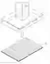
Referring to FIGS. 1 to 4, the flow diagram of the present invention is illustrated. The method of the present invention will be described herein.
The present invention has the following steps.
A substrate 1 is made of papers, adhesive tapes, acrylic fiber, woods, plastics,
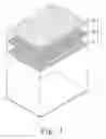
A plurality of plate layers 2 are selected. The plurality of plate layers 2 have different colors or textures. A layer of glues are coated on the plate layers by using a roller as so as to form a semi-product. The plate layers 2 includes a first plate layer 21, a second plate layer 22 and a third plate layer 23, etc. One surface of the first plate layer 21 coated with glue is adhered to a surface of the substrate 1. One surface of the second plate layer 22 coated with glue is adhered to another surface of the first plate layer 21 not glued. One surface of the third plate layer 23 coated with glue is adhered to another surface of the second plate layer 22 not glued. The process is performed one by one until all the plate layers are adhered to the lower layers. It is preferred the adhering operation is performed by a roller of a printing machine. Furthermore, the plate layers are selected from color papers or adhesive tapes, etc.
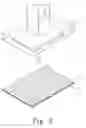
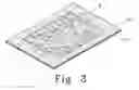
After completing above process, the semi-product is transferred to a cutting area. A pattern cutting unit 3 serves to punch upon the plate layers so as to form a plurality of cutting wires 4 as outlines of at least one small area 20.
Referring to FIG. 5, the structural schematic view of the present invention is illustrated. It is illustrated that the structure of the present invention includes a substrate 1, a plurality of plate layers of different colors or patterns are sequentially adhered upon the substrate 1. The plate layers 2 are formed with a plurality of cutting wires 4 so as to form a pattern.
In operation, the small areas 20 enclosed by the cutting wires 4 are torn down from the plate layers 2. For example if the small area 20a is torn, and then the color of the plate layer below the small area 20 is shown. Thereby to tear different plate layers, a pattern of different color is formed.
The present invention is thus described, it will be obvious that the same may be varied in many ways. Such variations are not to be regarded as a departure from the spirit and scope of the present invention, and all such modifications as would be obvious to one skilled in the art are intended to be included within the scope of the following claims.
Claims
What is claimed is:1. A method for forming a pattern on a substrate comprising the steps of;
locating a substrate;
adhering a plurality of plate layers upon the substrate one by one by gluing; the plurality of plate layers having different colors or textures;
transferring the substrate with the plurality of plate layers to a cutting area; and
punching upon the plate layers by a cutting unit so as to form a plurality of cutting wires as outlines of at least one small areas.
2. The stainless self-tapping screw as claimed in claim 1, wherein a material of the substrate is selected from one of papers, adhesive tapes, acrylic fiber, woods, amd plastics.
3. The stainless self-tapping screw as claimed in claim 1, wherein the plate layers are selected from one of colored papers and adhesive tapes.
4. The stainless self-tapping screw as claimed in claim 1, wherein the plate layer is glued by roller or by directly adhesion.
5. The stainless self-tapping screw as claimed in claim 1, wherein a glue not adhering to human skin is used in the gluing process.
6. A pattern forming device comprising:
a substrate;
a plurality of plate layers having different colors or textures; the plate layers being adhering upon the substrate one by one; the plurality of plate layers having cutting wires formed thereon; the cutting wires being formed with at least one small areas so that the small area can be torn away to display the color or patter of one of the plate layers below the torn small area so as to form a pattern.
Images & Drawings included:

Sources:
- United States Patent and Trademark Office - verify current appl. status at the USPTO↗
Similar patent applications:
- » 20080105950
SEMICONDUCTOR SUBSTRATE, METHOD OF MANUFACTURING THE SEMICONDUCTOR SUBSTRATE, SEMICONDUCTOR DEVICE AND PATTERN FORMING METHOD - » 20050167692
Semiconductor substrate, method of manufacturing the semiconductor substrate, semiconductor device and pattern forming method - » 20100038649
Mold, manufacturing method of mold, method for forming patterns using mold, and display substrate and display device manufactured by using method for forming patterns - » 20070275327
PHOTOSENSITIVE RESIN COMPOSITION, RESIST PATTERN FORMING METHOD, SUBSTRATE PROCESSING METHOD, AND DEVICE MANUFACTURING METHOD - » 20050221222
Photosensitive resin composition, resist pattern forming method, substrate processing method, and device manufacturing method - » 20060003269
Resist pattern forming method, substrate processing method, and device manufacturing method - » 20060014108
Resist pattern forming method based on near-field exposure, and substrate processing method and device manufacturing method using the resist pattern forming method - » 20130267092
Methods of forming a fine pattern on a substrate and methods of forming a semiconductor device having a fine pattern - » 20130207309
Minute convexo-concave pattern forming method and forming device, and transfer substrate producing method and transfer substrate - » 20110221077
Water repellant composition for substrate to be exposed, method for forming resist pattern, electronic device produced by the formation method, treatment method for imparting water repellency to substrate to be exposed, water repellant set for substrate to be exposed, and treatment method for imparting water repellency to substrate to be exposed using the same
Recent applications in this class:
- » 20230148211 2023-05-11
Three-dimensional decorative piece made of thermoplastic synthetic resin and method for producing the same - » 20230071952 2023-03-09
DECORATIVE SHEET, DECORATIVE PANEL, AND MANUFACTURING METHOD FOR DECORATIVE SHEET - » 20220250409 2022-08-11
PLATE AND MANUFACTURING METHOD THEREOF - » 20210394551 2021-12-23
PROCESS AND APPARATUS FOR DECORATING MANUFACTURED ARTICLES BY MEANS OF THERMOSETTING POWDER PAINT - » 20210347199 2021-11-11
DECORATIVE SHEET AND DECORATIVE MATERIAL USING SAME - » 20200384797 2020-12-10
THREE-DIMENSIONAL DECORATIVE PIECE MADE OF THERMOPLASTIC SYNTHETIC RESIN AND METHOD FOR PRODUCING THE SAME - » 20190337325 2019-11-07
Decoration sheet having discontinuous lenticular lens - » 20180117955 2018-05-03
DECORATIVE MULTI-LAYER COATING FOR HORIZONTAL AND VERTICAL SURFACES - » 20170341461 2017-11-30
Method of marking laminated jewelry - » 20150298495 2015-10-22
Member adhering decoration method