Carrier air heating system for SCR
US20060234173A1
2006-10-19
11/105,053
2005-04-13
✅ Patent granted
US 7,588,440 B2
2009-09-15
-
-
Steven B McAllister | Sarah Suereth
2025-08-14
Abstract:
A heat exchanger is provided in an air duct between an air heater and a windbox of a combustion means such as a boiler. Dilution air is carried to the heat exchanger from a dilution air fan in a separate duct. The heat in the air from the air heater is transferred to the dilution air via the heat exchanger and the heated dilution air is sent to vaporize ammonia before the ammonia is introduced into an exhaust duct with a selective catalytic reduction (SCR) chamber. A bypass valve is provided around the heat exchanger for blending heated and unheated air to control the temperature of the dilution air.
Assignee:
- Babcock & Wilcox Power Generation Group Inc. 50 🇺🇸 Barberton, OH, United States
Interested in similar patents?
Get notified when new applications in this technology area are published.
Classification:
F23L15/04 » CPC main
Heating of air supplied for combustion Arrangements of recuperators
B01D53/8628 » CPC further
Separation of gases or vapours; Recovering vapours of volatile solvents from gases; Chemical or biological purification of waste gases, e.g. engine exhaust gases, smoke, fumes, flue gases, aerosols,; Chemical or biological purification of waste gases; General processes for purification of waste gases; Apparatus or devices specially adapted therefor; Catalytic processes; Removing nitrogen compounds; Nitrogen oxides Processes characterised by a specific catalyst
B01D53/90 » CPC further
Separation of gases or vapours; Recovering vapours of volatile solvents from gases; Chemical or biological purification of waste gases, e.g. engine exhaust gases, smoke, fumes, flue gases, aerosols,; Chemical or biological purification of waste gases; General processes for purification of waste gases; Apparatus or devices specially adapted therefor; Catalytic processes Injecting reactants
F23J15/003 » CPC further
Arrangements of devices for treating smoke or fumes for supplying chemicals to fumes, e.g. using injection devices
B01D2251/2062 » CPC further
Reactants; Reductants; Ammonium compounds Ammonia
B01D2258/0283 » CPC further
Sources of waste gases; Other waste gases Flue gases
F01N3/2066 » CPC further
Exhaust or silencing apparatus having means for purifying, rendering innocuous, or otherwise treating exhaust for rendering innocuous by thermal or catalytic conversion of noxious components of exhaust characterised by methods of operation; Control specially adapted for catalytic conversion ; Methods of operation or control of catalytic converters Selective catalytic reduction [SCR]
F01N2240/02 » CPC further
Combination or association of two or more different exhaust treating devices, or of at least one such device with an auxiliary device, not covered by indexing codes or , one of the devices being a heat exchanger
F01N2610/02 » CPC further
Adding substances to exhaust gases the substance being ammonia or urea
F01N2610/10 » CPC further
Adding substances to exhaust gases the substance being heated, e.g. by heating tank or supply line of the added substance
F23J2219/10 » CPC further
Treatment devices Catalytic reduction devices
Y02E20/34 » CPC further
Combustion technologies with mitigation potential Indirect COmitigation, i.e. by acting on non COdirectly related matters of the process, e.g. pre-heating or heat recovery
Y02E20/34 » CPC further
Combustion technologies with mitigation potential Indirect COmitigation, i.e. by acting on non COdirectly related matters of the process, e.g. pre-heating or heat recovery
F23D14/66 IPC
Burners for combustion of a gas, e.g. of a gas stored under pressure as a liquid; Details, e.g. noise reduction means Preheating the combustion air or gas
F23L15/00 IPC
Heating of air supplied for combustion
F23J7/00 IPC
Arrangement of devices for supplying chemicals to fire
Description
FIELD AND BACKGROUND OF INVENTIONThe present invention relates generally to the field of fossil fuel combustion and emissions and in particular to an apparatus and method for reducing NOx wherein a heat exchanger is provided in an air duct between an air heater and a windbox of a combustion means, for transferring heat from the air to dilution air, which can be used to vaporize ammonia.
The reduction of NOx has long been a concern in the field of fossil fuel combustion, particularly with the operation of modern power plants. Oxides of nitrogen are a byproduct of the combustion of hydrocarbon fuels, such as pulverized coal, gas, or oil. One typical post-combustion process for lowering the NOx emissions is that of Selective Catalytic Reduction (SCR). SCR systems use a catalyst and a reactant such as ammonia gas to disassociate NOx to molecular nitrogen and water vapor.
Ducts are constructed to transport air and flue gas, separately, or in combination. Combustion of hydrocarbon fuels occurs within the boiler, creating hot flue gases that are directed through an exit to a flue or gas duct. Ammonia as a reactant is introduced into the same flue or gas duct via sparger tubes which form an ammonia injection grid (AIG) and spray ammonia. The ammonia is mixed with the hot flue gases. The ammonia/flue gas mixture then enters the SCR chamber wherein catalytic reductions take place between the ammonia/flue gas mixture and the catalytic material.
After leaving the SCR, the ammonia/flue gas mixture travels to an air preheater followed by a flue gas cleaning system such as a scrubber and then to the atmosphere via a stack.
At some point before the ammonia reaches the SCR, it is vaporized. Various systems are used to supply the heat necessary for ammonia vaporization. Many of these systems are based on heating the dilution air and then using this heat to vaporize the ammonia prior to the AIG. These systems range from heating with direct fired natural gas to heating with a steam coil or electric heater. Another system is disclosed in U.S. Pat. No. 5,296,206 in which a heat exchanger is used to heat the diluted air while extracting heat from the flue gas between the boiler exit and the SCR chamber inlet. When the hot dilution air is mixed with the ammonia entering the gas duct through the AIG, the ammonia is vaporized by the hot flue gas.
Use of an external heat source to vaporize ammonia is disadvantageous as described in the background section of U.S. Pat. No. 5,437,851. There is a need in the fossil fuel burning industry for a means of heating dilution air in which no external energy source is needed for the heating. There is also a need for a location for the means for heating that has relatively clean air thus minimizing concerns for deposition, fouling, corrosion, and erosion.
SUMMARY OF INVENTIONIt is an object of the present invention to provide a means for heating dilution air in which no external energy source is needed for the heating.
It is a further object of the present invention to provide a location for preheating dilution air that has clean air, wherein deposition, fouling, corrosion and erosion are avoided.
Accordingly, a heat exchanger is provided in an air duct between the air heater and the windbox for a combustion means such as a boiler. Dilution air is blown up to the heat exchanger from a dilution air fan in a separate duct. The dilution air is heated sufficiently by the heat exchanger and then sent to vaporize ammonia before the ammonia is transported to the AIG. A bypass valve is provided for blending heated and unheated air to control the temperature of the dilution air.
The various features of novelty which characterize the invention are pointed out with particularity in the claims annexed to and forming a part of this disclosure. For a better understanding of the invention, its operating advantages and specific objects attained by its uses, reference is made to the accompanying drawings and descriptive matter in which a preferred embodiment of the invention is illustrated.
BRIEF DESCRIPTION OF THE DRAWINGSIn the drawings:
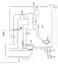
FIG. 1 is a schematic diagram of the present invention.
DESCRIPTION OF THE PREFERRED EMBODIMENTSReferring now to-the drawings, in which like reference numerals are used to refer to the same or similar elements, FIG. 1 shows a combustion system with an arrangement for heating dilution air to vaporize ammonia and a means for combusting a fossil fuel in the presence of air, which in turn leads to a post-combustion arrangement wherein hot flue gas is mixed with the vaporized ammonia and reacted with a catalyst in an SCR chamber.
The means for providing air to the combustion means for combusting a fossil fuel comprises an air duct 20 leading to the combustion means 40, a forced draft fan 22 at the inlet of the air duct 20, and an air heater 24 downstream from the air duct inlet.
The arrangement for heating dilution air to vaporize ammonia comprises a dilution air duct 30 leading to the air duct 20, a dilution air fan 32 at the inlet of the dilution air duct 30, and a heat exchanger 26 positioned between a windbox 42 of the combustion means 40 and the air heater 24, and a temperature control bypass valve 34 provided around the heat exchanger 26 between the dilution air fan 32 and an ammonia skid tank 60. The dilution air duct 30 is connected to the heat exchanger 26 within the air duct 20. Another duct 38 is provided between the heat exchanger 26 and the ammonia skid tank 60.
The combustion means 40 can be a boiler, or furnace which is used to convert fuel to operate a power plant for example.
The post-combustion arrangement of the system comprises a exhaust duct 50 beginning at the exit of the combustion means, an ammonia injection grid (AIG) 52, an SCR chamber 54, an air heater 24, and an outlet 58 from the exhaust duct 50 leading to a scrubber for cleaning remaining exhaust gas and. removing particulates.
The method of vaporizing ammonia prior to the SCR chamber 54 according to the present invention includes the following. Air is blown from the forced draft fan 22 into the air duct 20 at the air duct inlet. The air is preheated at the air heater 24 and then the heated air travels downstream to the heat exchanger 26. Dilution air is blown from the dilution air fan 32 at the inlet of the dilution air duct 30. The dilution air travels through the dilution air duct 30 to the heat exchanger 26 where a portion of the heat from the air within the air duct 20 is transferred by the heat exchanger 26 to the dilution air.
The heated dilution air then travels from the heat exchanger 26 to the ammonia via duct 38 to vaporize the ammonia in a portable ammonia skid tank 60 via. The dilution air traveling from the heat exchanger 26 to the ammonia skid tank 60 may also be blended with unheated air that is blown directly from the dilution air fan 32 to the ammonia tank skid 60 via bypass valve 34.
The partially heated air in the air duct 20 then travels through the windbox 42 and into the combustion means 40. A fuel such as oil, gas, or coal is fed into the combustion means through burners. The fuel is mixed with the partially heated air and burned producing a hot flue gas. The hot flue gas then exits the combustion means into exhaust duct 50.
The vaporized ammonia is introduced into the exhaust duct 50 via sparger tubes which form an ammonia injection grid (AIG) 52 and spray ammonia. The ammonia is mixed with the hot flue gas. The ammonia/flue gas mixture then enters the SCR chamber wherein catalytic reductions take place between the ammonia/flue gas mixture and the catalytic material.
After leaving the SCR, the ammonia/flue gas mixture travels to the portion of the air heater 24 in the exhaust duct 50, in which heat is absorbed to provide heat to the air in the air duct 20. The remaining ammonia/flue gas mixture then moves onto a flue gas cleaning system such as a scrubber and then to the atmosphere via a stack.
While a specific embodiment of the invention has been shown and described in detail to illustrate the application of the principles of the invention, it will be understood that the invention may be embodied otherwise without departing from such principles.
Claims
We claim:1. An arrangement for heating dilution air to vaporize ammonia comprising:
an air duct with a heat exchanger downstream from an air heater;
a dilution air duct for carrying dilution air to said heat exchanger in said air duct; and
a heated dilution air duct for carrying heated dilution air from said heat exchanger to a source of ammonia.
2. An apparatus according to claim 1, further comprising a bypass between said dilution air duct and said heated dilution air duct wherein air blown from said dilution air duct may be provided to said heated dilution air duct without being heated by said heat exchanger to be blended with heated dilution carried from said heat exchanger for controlling heated dilution air temperature.
3. A method for supplying the heat necessary for ammonia vaporization in a selective catalytic reduction (SCR) system comprising the steps of:
heating air in an air duct to provide heated air;
carrying said heated air to a heat exchanger;
carrying dilution air to said heat exchanger from a dilution air duct;
transferring a portion of heat from said heated air to said dilution air via a heat exchanger; and
carrying the heated dilution air to a source of ammonia.
4. A method according to claim 3, further comprising the step of blending the heated dilution air with unheated air to control dilution air temperature.
5. A method according to claim 4, wherein said unheated air is provided by a bypass around said heat exchanger.
6. A combustion system comprising:
an air duct with a heat exchanger downstream from an air heater;
a dilution air duct for carrying dilution air to said heat exchanger in said air duct;
a heated dilution air duct for carrying heated dilution air from said heat exchanger to a source of ammonia;
a combustion means downstream from said heat exchanger;
an exhaust duct arranged at an exit for said combustion means;
an ammonia injection grid in said exhaust duct and downstream from said combustion means, wherein said source of ammonia is connected to said ammonia injection grid for providing ammonia to said grid;
and a selective catalytic reduction (SCR) chamber downstream from said ammonia injection grid.
7. A combustion system according to claim 6, further comprising a scrubber, particulate remover, and stack downstream from and outside of said exhaust duct.
8. A combustion system according to claim 6, wherein said combustion means is a boiler.
9. A combustion system according to claim 6, wherein said combustion means includes a pulverizer.
Images & Drawings included:

Sources:
- United States Patent and Trademark Office - verify current appl. status at the USPTO↗
Recent applications in this class:
- » 20250129937 2025-04-24
Recuperative Burner - » 20240263779 2024-08-08
RECUPERATOR BURNER WITH A RECUPERATOR FOR GUIDING COUNTER-FLOWING FLUIDS - » 20220268440 2022-08-25
Rotary air preheater - » 20210293411 2021-09-23
Corrosion resistant air preheater with lined tubes - » 20210131662 2021-05-06
RECUPERATIVE GAS BURNER FOR INDUSTRIAL APPLICATIONS AND METHOD OF OPERATING THE SAME - » 20200224874 2020-07-16
Fluidized bed boiler plant and a method of preheating combustion gas in a fluidized bed boiler plant - » 20170067634 2017-03-09
Recuperator burner with auxiliary heat exchanger - » 20160238245 2016-08-18
FLUE GAS HEAT RECOVERY SYSTEM - » 20160123583 2016-05-05
RECUPERATOR BURNER - » 20150111160 2015-04-23
High-temperature battery integrated into a steam power station
Recent applications for this Assignee:
- » 20140000311 2014-01-02
Method for controlling acidic compounds produced for oxy-combustion processes - » 20130264725 2013-10-10
Wet scrubber tray - » 20130156665 2013-06-20
Dry sorbent injection during non-steady state conditions in dry scrubber - » 20130156664 2013-06-20
Dry sorbent injection during steady-state conditions in dry scrubber - » 20120100052 2012-04-26
System and method for protection of SCR catalyst and control of multiple emissions - » 20120042779 2012-02-23
Integrated flue gas dehumidification and wet cooling tower system - » 20110250551 2011-10-13
Oxy-fuel combustion oxidant heater internal arrangement - » 20110232490 2011-09-29
Chemical compounds for the removal of carbon dioxide from gases - » 20110229388 2011-09-22
System and method for increasing the service life and/or catalytic activity of an SCR catalyst and control of multiple emissions - » 20110188338 2011-08-04
Stepped down gas mixing device