Holdable food tray
US20060249424A1
2006-11-09
11/430,566
2006-05-09
Abstract:
A holdable food tray comprises specially positioned punch-out holes configured and sized for passing fingers through so as to improve holdability of the food tray.
Inventors:
- Liborio Mormina 1 🇨🇦 Montreal, Canada
- Giovanni Gentile 1 🇨🇦 Pierrefonds, Canada
- Marco Giordano 1 🇨🇦 Montreal, Canada
Interested in similar patents?
Get notified when new applications in this technology area are published.
Classification:
B65D5/4208 » CPC main
Rigid or semi-rigid containers of polygonal cross-section, e.g. boxes, cartons or trays, formed by folding or erecting one or more blanks made of paper; Details of containers or of foldable or erectable container blanks Means facilitating suspending, lifting, handling, or the like of containers
B65D25/30 » CPC further
Details of other kinds or types of rigid or semi-rigid containers; Handles Hand holes
B65D1/34 IPC
Containers having bodies formed in one piece, e.g. by casting metallic material, by moulding plastics, by blowing vitreous material, by throwing ceramic material, by moulding pulped fibrous material, by deep-drawing operations performed on sheet material Trays or like shallow containers
Description
This application claims priority based on provisional application 60/679,066 filed May 9, 2005
BACKGROUND OF THE INVENTION1. Field of the Invention
The invention relates generally to disposable food containers but more particularly to a food container convertible to a holdable food tray.
2. Background of the Invention
Fast food outlets serve they foods in various types of disposable containers ranging from simple paper wraps to more elaborate containers having hingedly openable lids. These are often used as food trays for people on the run who eat in their cars. Unfortunately, these trays are not always easy to hold in one's hands.
SUMMARY OF THE INVENTIONIt is a main advantage of this invention to provide for a food tray having improved hand holdability features to facilitate holding with the hands.
In order to do so, the invention comprises specially positioned punch-out holes configured and sized for passing fingers through so as to improve holdability of the food tray.
There has thus been outlined, rather broadly, the more important features of the invention in order that the detailed description thereof that follows may be better understood, and in order that the present contribution to the art may be better appreciated. There are additional features of the invention that will be described hereinafter and which will form the subject matter of the claims appended hereto.
In this respect, before explaining at least one embodiment of the invention in detail, it is to be understood that the invention is not limited in its application to the details of construction and to the arrangements of the components set forth in the following description or illustrated in the drawings. The invention is capable of other embodiments and of being practiced and carried out in various ways. Also, it is to be understood that the phraseology and terminology employed herein are for the purpose of description and should not be regarded as limiting.
As such, those skilled in the art will appreciate that the conception, upon which this disclosure is based, may readily be utilized as a basis for the designing of other structures, methods and systems for carrying out the several purposes of the present invention. It is important, therefore, that the claims be regarded as including such equivalent constructions insofar as they do not depart from the spirit and scope of the present invention.
Further, the purpose of the foregoing abstract is to enable the U.S. Patent and Trademark Office and the public generally, and especially the scientists, engineers and practitioners in the art who are not familiar with patent or legal terms or phraseology, to determine quickly from a cursory inspection the nature and essence of the technical disclosure of the application. The abstract is neither intended to define the invention of the application, which is measured by the claims, nor is it intended to be limiting as to the scope of the invention in any way.
These together with other objects of the invention, along with the various features of novelty which characterize the invention, are pointed out with particularity in the claims annexed to and forming a part of this disclosure. For a better understanding of the invention, its operating advantages and the specific objects attained by its uses, reference should be had to the accompanying drawings and descriptive matter in which there is illustrated preferred embodiments of the invention.
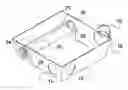
BRIEF DESCRIPTION OF THE PREFERRED EMBODIMENTFIG. 1 Isometric view of a first embodiment of a holdable food tray with no lid on.
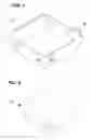
FIG. 2 Isometric view of the embodiment of FIG. 1 with a lid on.
FIG. 3 Top view of the embodiment of FIG. 1.
FIG. 4ab Side views of a second embodiment of a holdable food tray with an integrated lid open and closed, respectively.
FIG. 5abc Isometric views of a third embodiment of a holdable food tray with a finger cylinder, detail of the cylinder overlap, and with food inside the tray, respectively.
DETAILED DESCRIPTION OF THE PREFERRED EMBODIMENTA holdable food tray (10) has at least one but preferably a pair of punch-out holes (12, 12′) through which a user's finger passes, usually the pinkie finger entering by hole (12) and exiting by hole (12′) so as to hold the holdable food tray (10). The rest of the fingers can be used for holding the food (14). The general construction of the holdable food tray (10) is in other points similar to food containers as known in the art.
If a user has very small hands, at least one loop (16) and an optional 2nd loop (16′) can be used for inserting the user's finger, usually the thumb. Both loops (16, 16′) can be used by inserting the finger diagonally through both loops (16, 16′). It is also a way of not putting one's finger inside the holdable food tray (10) and provides an alternate way of holding it.
Users having very large hands can have one of their fingers like, for example, their pinkie finger hold the holdable food tray (10) underneath by its bottom and punch-out one or more larger punch-out opening(s) (18, 18′) wherein they can pass their other fingers to hold the food (14).
Alternatively, in a third embodiment, as per FIG. 5ab, a cylinder (20) can be used for inserting a finger. That way, the finger does not make contact with the food which can sometimes be oily or greasy. The cylinder (20) is fixedly attached at both its distal end (22) and its proximal end (24) to the holdable food tray (10) by way of tabs (25, 25′) which can be set either inside or outside the cylinder as per FIG. 5a. The cylinder (20) is allowed to expand in diameter (as in FIG. 5b) by having a freely moving overlap (26) so as to allow expansion so that a finger can be inserted while at the same time being somewhat held tightly by tapering off towards the distal end (22). Alternatively, both the proximal and the distal ends (22, 24) can be opened and the overlap is continuous from the proximal end (22) to the distal end (24). In such a case, obviously, only tabs (25) located outside the cylinder are feasible.
The holdable food tray (10) can be turned 180 degrees from the views shown so as to be used by a left handed person.
The punch-out holes (12, 12′) and punch-out openings (18) are perforated into the holdable food tray (10) at the manufacturing stage and the loop (16) is also created at the manufacturing stage and so is the cylinder (20) by processes known in the art, whether the holdable food tray (10) is made out of cardboard, plastics, styrofoam or other materials useable for making food containers.
As to a further discussion of the manner of usage and operation of the present invention, the same should be apparent from the above description. Accordingly, no further discussion relating to the manner of usage and operation will be provided.
With respect to the above description then, it is to be realized that the optimum dimensional relationships for the parts of the invention, to include variations in size, materials, shape, form, function and manner of operation, assembly and use, are deemed readily apparent and obvious to one skilled in the art, and all equivalent relationships to those illustrated in the drawings and described in the specification are intended to be encompassed by the present invention.
Therefore, the foregoing is considered as illustrative only of the principles of the invention. Further, since numerous modifications and changes will readily occur to those skilled in the art, it is not desired to limit the invention to the exact construction and operation shown and described, and accordingly, all suitable modifications and equivalents may be resorted to, falling within the scope of the invention.
Claims
1. A holdable food tray having a general construction similar to food containers and comprising:
at least one but preferably a pair of punch-out holes through which a user's finger passes so as to hold the holdable food tray.
2. A holdable food tray as in claim 1 further comprising:
at least one loop used for inserting a user's finger.
3. A holdable food tray as in claim 2 wherein:
a 2nd loop allows a user's finger to pass diagonally through both said loops.
4. A holdable food tray as in claim 1 wherein:
a punch-out opening allowing a user to pass their fingers to hold food.
5. A holdable food tray as in claim 1 wherein:
a cylinder fixedly attached at both its distal end and its proximal end to said holdable food tray;
said cylinder being allowed to expand in diameter by having a freely moving overlap so as to allow expansion so that a finger can be inserted and held tightly.
6. A holdable food tray as in claim 1 further comprising:
a first loop and a 2nd loop to allow a user's finger to pass diagonally through both said loops.
7. A holdable food tray as in claim 6 wherein:
a punch-out opening allowing a user to pass their fingers to hold food.
8. A holdable food tray as in claim 2 wherein:
a cylinder fixedly attached at both its distal end and its proximal end to said holdable food tray;
said cylinder being shaped so as to taper towards said distal end and being allowed to expand in diameter by having a freely moving overlap so as to allow expansion so that a finger can be inserted and held tightly.
9. A holdable food tray as in claim 6 wherein:
a cylinder fixedly attached at both its distal end and its proximal end to said holdable food tray;
said cylinder being shaped so as to taper towards said distal end and being allowed to expand in diameter by having a freely moving overlap so as to allow expansion so that a finger can be inserted and held tightly.
10. A holdable food tray as in claim 5 wherein:
said cylinder being fixedly attached to said holdable food tray by way of tabs.
11. A holdable food tray as in claim 10 wherein:
said tabs being set outside said cylinder.
12. A holdable food tray as in claim 10 wherein:
said tabs being set inside said cylinder.
13. A holdable food tray as in claim 5 wherein:
only one end of said cylinder is open.
14. A holdable food tray as in claim 5 wherein:
both ends of said cylinder are open.
Images & Drawings included:


Sources:
- United States Patent and Trademark Office - verify current appl. status at the USPTO↗
Recent applications in this class:
- » 20250091758 2025-03-20
PRODUCT PACKAGE - » 20240092527 2024-03-21
Protective insert for basiloid package - » 20230249871 2023-08-10
ONE-PIECE CARTON WITH HANG TAB - » 20220306335 2022-09-29
PACKAGES HAVING ISOLATED HANDLE STRUCTURES AND BLANKS THEREFOR - » 20220177181 2022-06-09
Consumer product package and method of assembly - » 20210276759 2021-09-09
Box for luminaire and method for installing luminaire - » 20210214117 2021-07-15
Roller assembly, package including the roller assembly and method of using the package - » 20210016917 2021-01-21
Package assembly - » 20200391900 2020-12-17
Packaging box - » 20200331654 2020-10-22
Mountable container