Method of rigidifying a foam panel and a foam panel
US20060263575A1
2006-11-23
11/437,597
2006-05-18
Abstract:
A foam panel and method of reinforcing the same, includes a first sheet and a second sheet in parallel spaced relation defining a sandwich cavity between the first sheet and the second sheet. Reinforcing strips of sheeting material are positioned on edge transversely across the sandwich cavity, with one edge engaging the first sheet and an opposed edge engaging the second sheet. Foam insulation fills the remainder of the sandwich cavity.
Interested in similar patents?
Get notified when new applications in this technology area are published.
Classification:
B32B3/00 » CPC main
Layered products comprising a layer with external or internal discontinuities or unevennesses, or a layer of non-planar form ; Layered products having particular features of form
B32B3/12 » CPC further
Layered products comprising a layer with external or internal discontinuities or unevennesses, or a layer of non-planar form ; Layered products having particular features of form characterised by a discontinuous layer, i.e. formed of separate pieces of material characterised by a layer of regularly- arranged cells, e.g. a honeycomb structure
B32B3/20 » CPC further
Layered products comprising a layer with external or internal discontinuities or unevennesses, or a layer of non-planar form ; Layered products having particular features of form characterised by a discontinuous layer, i.e. formed of separate pieces of material characterised by an internal layer formed of separate pieces of material which are juxtaposed side-by-side of hollow pieces, e.g. tubes; of pieces with channels or cavities
B32B5/20 » CPC further
Layered products characterised by the non- homogeneity or physical structure, i.e. comprising a fibrous, filamentary, particulate or foam layer; Layered products characterised by having a layer differing constitutionally or physically in different parts characterised by features of a layer of foamed material foamed
B32B7/03 » CPC further
Layered products characterised by the relation between layers; Layered products characterised by the relative orientation of features between layers, or by the relative values of a measurable parameter between layers, i.e. products comprising layers having different physical, chemical or physicochemical properties; Layered products characterised by the interconnection of layers with respect to the orientation of features
B32B9/00 » CPC further
Layered products characterised by particular substances used
B32B9/00 » CPC further
Layered products comprising a layer of a particular substance not covered by groups -
B32B9/046 » CPC further
Layered products comprising a layer of a particular substance not covered by groups - comprising such substance as the main or only constituent of a layer, next to another layer of a of foam
B32B13/045 » CPC further
Layered products comprising a a layer of water-setting substance, e.g. concrete, plaster, asbestos cement, or like builders' material comprising such substance as the main or only constituent of a layer, next to another layer of a of foam
B32B2250/03 » CPC further
Layers arrangement 3 layers
B32B2250/40 » CPC further
Layers arrangement Symmetrical or sandwich layers, e.g. ABA, ABCBA, ABCCBA
B32B2307/304 » CPC further
Properties of the layers or laminate having particular thermal properties Insulating
B32B2307/306 » CPC further
Properties of the layers or laminate having particular thermal properties Resistant to heat
B32B2307/54 » CPC further
Properties of the layers or laminate having particular mechanical properties Yield strength; Tensile strength
B32B2307/558 » CPC further
Properties of the layers or laminate having particular mechanical properties Impact strength, toughness
B32B2307/718 » CPC further
Properties of the layers or laminate; Other properties Weight, e.g. weight per square meter
B32B2419/04 » CPC further
Buildings or parts thereof Tiles for floors or walls
Y10T428/233 » CPC further
Stock material or miscellaneous articles; Sheet including cover or casing Foamed or expanded material encased
Y10T428/24174 » CPC further
Stock material or miscellaneous articles; Structurally defined web or sheet [e.g., overall dimension, etc.] including sheet or component perpendicular to plane of web or sheet
B32B7/00 IPC
Layered products characterised by the relation between layers; Layered products characterised by the relative orientation of features between layers, or by the relative values of a measurable parameter between layers, i.e. products comprising layers having different physical, chemical or physicochemical properties; Layered products characterised by the interconnection of layers
Description
FIELD OF THE INVENTIONThe present invention relates to a method of rigidifying a foam panel and a foam panel that has been made more rigid by application of the method.
BACKGROUND OF THE INVENTIONThere are some environments in which it is highly desirable for a foam panel to have increased rigidity. One example is when the foam panel is used to construct a building in a geographic region that is periodically subjected to hurricane force winds. Another example is when the foam panel is intended for use as flooring.
U.S. Pat. No. 5,519,971 (Ramirez 1996) discloses a sandwich panel having a foam core. Spacer blocks are positioned between the panel members to improve the rigidity of the panel.
SUMMARY OF THE INVENTIONAccording to one aspect of the present invention there is provided a method of rigidifying a foam panel. A first step involves positioning a first sheet and a second sheet in parallel spaced relation defining a sandwich cavity between the first sheet and the second sheet. A second step involves positioning reinforcing strips of sheeting material on edge transversely across the sandwich cavity with one edge engaging the first sheet and an opposed edge engaging the second sheet. A third step involves filling a remainder of the sandwich cavity with foam insulation.
According to another aspect of the present invention there is provided a foam panel, which includes a first sheet and a second sheet in parallel spaced relation defining a sandwich cavity between the first sheet and the second sheet. Reinforcing strips of sheeting material are positioned on edge transversely across the sandwich cavity, with one edge engaging the first sheet and an opposed edge engaging the second sheet. Foam insulation fills a remainder of the sandwich cavity.
BRIEF DESCRIPTION OF THE DRAWINGSThese and other features of the invention will become more apparent from the following description in which reference is made to the appended drawings, the drawings are for the purpose of illustration only and are not intended to in any way limit the scope of the invention to the particular embodiment or embodiments shown, wherein:
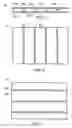
FIG. 1 is a top plan view, in section, of a foam panel constructed in accordance with the teaching of the present method.
FIG. 2 is a front elevation view, in section, of the foam panel illustrated in FIG. 1.
FIG. 3 is a front elevation view, in section, of an alternative of the foam panel illustrated in FIG. 1.
DETAILED DESCRIPTION OF THE PREFERRED EMBODIMENTThe preferred embodiment, a foam panel generally identified by reference numeral 10, will now be described with reference to FIGS. 1 through 3.
Structure and Relationship of Parts:
Referring now to FIG. 1, there is shown foam panel 10, including a first sheet 12 and a second sheet 14 in parallel spaced relation defining a sandwich cavity 16 between first sheet 12 and second sheet 14. Reinforcing strips 18 of sheeting material on edge transversely across sandwich cavity 16 with one edge 20 engaging first sheet 12 and an opposed edge 22 engaging second sheet 14. Referring to FIG. 2, reinforcing strips are shown spaced throughout foam panel 10, and extend the height of panel 10. Reinforcing strips 18 are shown to extend in parallel spaced relation for substantially the entire width of sandwich cavity 16. Referring to FIG. 3, reinforcing strips 18 may also extend substantially the entire length of sandwich cavity 16. Reinforcing strips 18 as shown are made from the same sheet material as first sheet 12 and second sheet 14, only cut into strips. Foam insulation 24 such as non-combustible foam glass is used to fill sandwich cavity 16. First sheet 12, second sheet 14, and reinforcing strips 18 are made from non-combustible material such as magnesium oxide, calcium silicate or cement.
Operation:
The use of foam panel 10 will now be discussed with reference to FIGS. 1 through 3. Referring to FIG. 1, foam panel 10 is prepared with reinforcing strips 18 inserted between first sheet 12 and second sheet 14. Referring to FIG. 2, foam panel 10 is then able to be used either as a wall piece or a floor piece in a properly constructed structure with adequate reinforcement.
Variations:
The foam panel described above represents the preferred embodiment. It will be apparent to one skilled in the art that the reinforcing strips need not extend for the entire length or width of the sandwich cavity. It will also be apparent to one skilled in the art that the reinforcing strips need not be in parallel spaced relation. This version is preferred, merely because it provides what is believed to be the best support. It is not possible to illustrate all possible variations. One variation is that the reinforcing strips could be in parallel spaced relation, but extend in a diagonal orientation. Another variation is that the reinforcing strips could be positioned randomly or in a non-parallel pattern, but be sufficient in number and sufficiently spaced to provide the desired rigidity.
In this patent document, the word “comprising” is used in its non-limiting sense to mean that items following the word are included, but items not specifically mentioned are not excluded. A reference to an element by the indefinite article “a” does not exclude the possibility that more than one of the element is present, unless the context clearly requires that there be one and only one of the elements.
It will be apparent to one skilled in the art that modifications may be made to the illustrated embodiment without departing from the spirit and scope of the invention as hereinafter defined in the Claims.
Claims
1. A method of rigidifying a foam panel, comprising:
positioning a first sheet and a second sheet in parallel spaced relation defining a sandwich cavity between the first sheet and the second sheet;
positioning reinforcing strips of sheeting material on edge transversely across the sandwich cavity with one edge engaging the first sheet and an opposed edge engaging the second sheet; and
filling a remainder of the sandwich cavity with foam insulation.
2. A foam panel comprising:
a first sheet and a second sheet in parallel spaced relation defining a sandwich cavity between the first sheet and the second sheet;
reinforcing strips of sheeting material positioned on edge transversely across the sandwich cavity with one edge engaging the first sheet and an opposed edge engaging the second sheet; and
foam insulation filling the sandwich cavity.
3. The foam panel as defined in claim 2, wherein the reinforcing strips extend for one of substantially the entire length or substantially the entire width of the sandwich cavity.
4. The foam panel as defined in claim 2, wherein the reinforcing strips are arranged in parallel spaced relation.
5. The foam panel as defined in claim 2, wherein the first sheet, the second sheet, and the reinforcing strips are made from non-combustible material.
6. The foam panel as defined in claim 5, wherein the non-combustible material is one of magnesium oxide, calcium silicate or cement.
7. The foam panel as defined in claim 2, wherein the foam insulation is non-combustible foam glass.
8. A foam panel comprising:
a first sheet and a second sheet in parallel spaced relation defining a sandwich cavity between the first sheet and the second sheet;
reinforcing strips of sheeting material on edge transversely across the sandwich cavity with one edge engaging the first sheet and an opposed edge engaging the second sheet, the reinforcing strips extending in parallel spaced relation for one of substantially the entire length or substantially the entire width of the sandwich cavity; and
foam insulation filling the sandwich cavity.
9. The foam panel as defined in claim 8, wherein the first sheet, the second sheet, and the reinforcing strips are made from non-combustible material.
10. The foam panel as defined in claim 9, wherein the non-combustible material is one of magnesium oxide, calcium silicate or cement.
11. The foam panel as defined in claim 8, wherein the foam insulation is non-combustible foam glass.
Images & Drawings included:

Sources:
- United States Patent and Trademark Office - verify current appl. status at the USPTO↗
Recent applications in this class:
- » 20180065334 2018-03-08
Erosion resistant and hydrophobic article - » 20150298421 2015-10-22
COMPOSITE MATERIALS AND STRUCTURES - » 20150202834 2015-07-23
LAMINATION TRANSFER FILMS FOR FORMING ANTIREFLECTIVE STRUCTURES - » 20140014289 2014-01-16
ENHANCED-EFFICIENCY ENERGY RECOVERY VENTILATION CORE - » 20130236322 2013-09-12
Erosion resistant and hydrophobic article - » 20130115437 2013-05-09
Disposable absorbent pad - » 20130089713 2013-04-11
ARTICLE PRINTED WITH INFRARED DYE - » 20130065080 2013-03-14
METHOD FOR MANUFACTURING CLAD MATERIAL AND EQUIPMENT FOR MANUFACTURING THE SAME - » 20130040083 2013-02-14
METHOD FOR MANUFACTURING MAGNESIUM-ALUMINUM ALLOY CASING - » 20130029104 2013-01-31
Plastic product with three dimensional pattern and manufacturing method of the same