Sealant assemblies and methods
US20060272249A1
2006-12-07
11/128,779
2005-05-13
Abstract:
Sealant assemblies and methods are provided for sealing an interface between a surface and a projection extending from the surface. The sealant assembly includes a body portion circumscribing an area to form a sealant pocket and a filling sealant at least partially filling the sealant pocket. The filling sealant and the body portion comprise substantially the same material.
Inventors:
- Ronald J. Janoski 4 🇺🇸 Chagrin Falls, OH, United States
- Mark C. Rundo 1 🇺🇸 Sarasota, FL, United States
- Jonathan A. Karas 1 🇺🇸 Twinsburg, OH, United States
Assignee:
- WTT Systems, LLC 1 🇺🇸 Chagrin Falls, OH, United States
Interested in similar patents?
Get notified when new applications in this technology area are published.
Classification:
E04D13/1407 » CPC main
Special arrangements or devices in connection with roof coverings; Protection against birds ; Roof drainage; Sky-lights; Junctions of roof sheathings to chimneys or other parts extending above the roof for flat roofs
E04B1/70 IPC
Constructions in general; Structures which are not restricted either to walls, e.g. partitions, or floors or ceilings or roofs; Insulation or other protection; Elements or use of specified material therefor Drying or keeping dry, e.g. by air vents
Description
FIELD OF THE INVENTIONThe present invention relates to sealant assemblies and methods, and more particularly, to sealant assemblies and methods adapted to seal an interface between a surface and a projection extending from the surface.
BACKGROUND OF THE INVENTIONBuildings commonly incorporate roof surfaces designed to repel water and prevent water from leaking into interior areas of the building. Frequently, roof surfaces are also designed to accommodate one or more roof projections extending from the roof surface. For example, it is known to penetrate a roof surface with an exhaust pipe to allow venting of gases generated within the building. When roof projections are necessary, special care must be taken to avoid leak paths at the interface between the roof surface and the roof projection.
In an effort to prevent leaks, it is known to treat the interface area between the exhaust pipe and the roof surface with a sealant assembly. Conventional sealant assemblies are typically formed by circumscribing the exhaust pipe with a body portion to create a roof pocket about the exhaust pipe. Once the roof pocket is formed, a filling sealant is introduced into the roof pocket to complete the sealant assembly.
While frequently useful in various applications, conventional sealant assemblies may fail due to environmental exposure. For example, conventional sealant assemblies include a body portion and a filling sealant that comprise different materials having substantially different coefficients of expansion. The differing coefficients of expansion can result in fracture of the interface between the body portion and the filling sealant as components of the assembly expand and contract at different rates during heating and cooling cycles. Moreover, forming the body portion and the filling sealant from different materials may discourage or prevent integral bonding that may further contribute to failure of any attachment interface between the body portion and the filling sealant.
For the reasons set forth above, conventional sealant assemblies may eventually degrade such that the body portion and the filling sealant are disassociated from one another. Such disassociation can contribute to leak-path formation that can lead to unnecessary and potentially catastrophic water damage within the building. Disassociation of the body portion can also introduce a loose object on the roof surface that might introduce a tripping hazard. A disassociated body portion may also tumble from the roof and thereafter present a dangerous falling object.
SUMMARY OF THE INVENTIONAccordingly, it is an aspect of the present invention to obviate problems and shortcomings of conventional sealant assemblies and methods. More particularly, it is an aspect of the present invention to provide sealant assemblies and methods that discourage disassociation between the body portion and the filling sealant of the sealant assembly.
In accordance with one aspect, a sealant assembly is provided for sealing an interface between a surface and a projection extending from the surface. The sealant assembly includes a body portion circumscribing an area to form a sealant pocket. The sealant assembly further includes a filling sealant at least partially filling the sealant pocket. The filling sealant and the body portion comprise substantially the same material.
In accordance with another aspect, a method of sealing an interface between a surface and a projection extending from the surface is provided. The method includes the step of positioning a body portion on the surface with the body portion circumscribing the projection and the projection extending through a sealant pocket defined by the body portion and the surface. The method further includes the step of adding a filling sealant into the sealant pocket, wherein the filling sealant subsequently solidifies such that the body portion and the solidified filling sealant form a solid sealant assembly with the body portion and the solidified filling sealant comprising substantially the same material.
In accordance with still another aspect, a sealant assembly is provided. The sealing assembly includes a body portion circumscribing an area to form a sealant pocket and a solidified filling sealant within the area and filling at least a portion of the sealant pocket. The sealant assembly is formed by a process including the step of positioning the body portion on a surface with the body portion circumscribing a projection extending from the surface. The process further includes the step of adding a filling sealant into the sealant pocket, wherein the filling sealant is substantially contained within the sealant pocket. Still further, the process includes the step of permitting the filling sealant to solidify such that the body portion and the solidified filling sealant form a solid sealant assembly with the body portion and the solidified filling sealant comprising substantially the same material.
BRIEF DESCRIPTION OF THE DRAWINGSThe foregoing and other features and advantages of the present invention will become apparent to those skilled in the art to which the present invention relates upon reading the following description with reference to the accompanying drawings, in which:
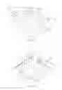
FIG. 1A is a perspective view demonstrating an exemplary step of assembling a body portion to circumscribe a projection extending from the surface;
FIG. 1B is a perspective view of an assembled body portion;
FIG. 1C is a perspective view demonstrating an exemplary step of adding a filling sealant into a sealant pocket;
FIG. 1D is a perspective view of an exemplary sealant assembly in accordance with aspects of the present invention;
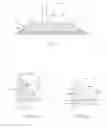
FIG. 2 is a sectional view of the sealant assembly taken at line 2-2 of FIG. 1D;
FIG. 3 is a top plan view of an exemplary corner element in accordance with aspects of the present invention;
FIG. 4A is a sectional view of the corner element along line 4A-4A of FIG. 3;
FIG. 4B is a sectional view of the corner element along line 4B-4B of FIG. 3
FIG. 5 is a left side elevational view of the corner element of FIG. 3;
FIG. 6 is a front elevational view of the corner element of FIG. 3;
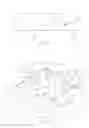
FIG. 7 is an assembled body portion in accordance with another exemplary embodiment of the present invention;
FIG. 8 is a sectional view of the body portion along line 8-8 of FIG. 7; and
FIG. 9 is another embodiment of a corner element in accordance with aspects of the present invention.
DETAILED DESCRIPTION OF EXAMPLE EMBODIMENTSCertain terminology is used herein for convenience only and is not to be taken as a limitation on the present invention. Further, in the drawings, the same reference numerals are employed for designating the same elements, and in order to clearly and concisely illustrate the present invention, certain features may be shown in somewhat schematic form.
FIGS. 1A-1D illustrate an exemplary method of providing a sealant assembly 20 adapted to seal an interface 204 between a surface 200 and one or more projections 202 extending from the surface 200. Sealant assemblies and methods herein may be applied in a wide range of applications. For instance, sealant assemblies may be used in applications where it is necessary to provide a fluid seal at an interface between a projection and a surface. In one example, the sealant assembly can be used to seal an interface between a roof surface and a vent pipe extending from the roof surface.
Sealant assemblies herein include a body portion that may circumscribe a single projection or any plurality of projections in accordance with aspects of the present invention. Body portions may be provided in a wide variety of shapes and/or sizes depending on the particular application. Moreover, the body portion may be provided as a single piece or might be provided as a plurality of pieces that can be assembled together to circumscribe the one or more projections. For instance, the body portion might comprise a continuous ring in a variety of shapes such as a continuous circular, oval, square, triangular, rectangular, or other continuous shape that can circumscribe a projection. The continuous ring can be placed over the top of the projection to circumscribe the projection adjacent the interface. In further embodiments, the ring may be split so that it is not necessary to place the ring over the top of the projection. For example, the ring may be split at a single location wherein the projection may be laterally inserted through the slit to enter the interior area of the ring. In another example, the ring may be split at two locations, wherein the ring halves may be closed around the projection to circumscribe the projection.
In still further examples, the body portion might comprise a plurality of corner elements adapted to at least partially circumscribe the projection. For example, as shown in FIGS. 1A-1D, a body portion 30 includes a plurality of corner elements 40 that are arranged to at least partially circumscribe the one or more projections 202. One exemplary corner element 40 is illustrated in FIGS. 3-6. As shown in FIG. 3, the corner element 40 can include a first extension arm 42 extending along a first extension axis 42a and a second extension arm 44 extending along a second extension axis 44a. As shown, the first extension axis 42a and second extension axis 44a are substantially perpendicular with respect to one another. It is also contemplated that the first and second extension axis may be located at different angular orientations depending on the shape of the body portion. For example, the first and second extension axis might be located at an angle of 60 degrees from one another to form a triangular body portion having three corner elements.
The illustrated corner element is shown to include relatively sharp corners. In further embodiments, the corner elements may comprise rounded corners to reduce stress points. For example, the corner element can comprise a first and second extension arm together with a rounded corner portion positioned between the first and second extension arm. In further embodiments, the entire corner element may comprise a rounded corner portion.
As shown in the illustrated embodiment, the extension arms 42, 44 comprise the same length. It is contemplated that the extension arms, if provided, may be longer or shorter than the relative length illustrated in the figures. Moreover, it is contemplated that the extension arms might comprise different lengths in further embodiments.
In accordance with exemplary embodiments of the present invention, the first extension arm 42 can include a first end portion 46a with a first substantially flat surface 48a that is substantially perpendicular to the first extension axis 42a. Similarly, the second extension arm 44 can include a second end portion 46b with a second substantially flat surface 48b that is substantially perpendicular to the second extension axis 44a. Providing the end portions with a substantially flat surface that is substantially perpendicular to the respective extension axis can facilitate connection of body portion elements. For example, end portions with perpendicular surfaces can allow compression of the end portions without significant development of shear stress and without deforming the end portions away from the extension axis. In contrast, compression of diagonal surfaces can develop significant shear stresses and might wedge against each other to deform the end portions away from the extension axis and therefore interfere with the fastening process.
In further examples, end portions of body components may have alternative configurations to facilitate connection of the components to one another. For example, FIG. 9 depicts a corner element 140 including a first end portion 146a with a tongue 142 and a second end portion 146b with a groove 144. When fastening a plurality of corner elements together, the tongue 142 of one corner element may be inserted within a groove 144 of another corner element to link the corner elements to one another. Providing a tongue and groove arrangement can facilitate fastening the end portions together and can increase the overall strength of the subsequently formed joint.
As shown in FIGS. 4A, 4B, 5 and 6 each corner element can include a substantially flat base 42b, 44b adapted to rest on a substantially flat surface 200. The corner elements further include boundary surfaces 42c, 44c adapted to at least partially define a perimeter boundary of the interior area 32 of the body portion 30. The corner elements further include an outer surface 42d, 44d extending between the corresponding flat bases 42b, 44b and boundary surfaces 42c, 44c. As shown in FIGS. 4A and 4B, the outer surface, boundary surface, and flat base can form a triangular configuration although other configurations may be employed in accordance with aspects of the present invention.
FIG. 7 is an assembled body portion 130 in accordance with another embodiment of the present invention. The body portion 130 includes at least a pair of intermediate segments 50a, 50b. The intermediate segments, if provided, can extend at least one dimension of the body portion to create an enlarged sealant pocket 134. In the illustrated embodiment, a second pair of intermediate segments 52a, 52b is also provided to extend a second dimension of the body portion to further enlarge the sealant pocket 134.
The intermediate segments, if provided, can include a wide variety of sizes to customize the size of the sealant pocket. For example, the first pair of intermediate segments 50a, 50b may have a first length and the second pair of intermediate segments 52a, 52b may have a second length. The first and second lengths may be equal or different from one another depending on the desired size of the body portion. For example, the intermediate segments 50a, 50b, 52a, 52b can have substantially identical lengths to form a substantially square shaped body portion. In further examples, the first pair of intermediate segments 50a, 50b may have a different length than the second pair of segments 52a, 52b to form a substantially rectangular shaped pitch pocket. In still further examples, only one pair of segments is used to extend the length of the pitch pocket in a single desired direction. In further examples, the body portion may be provided as a kit with four relatively long intermediate segments. The relatively long intermediate segments may be cut on site to provide a customized body portion having an appropriate size. Customizing the body portion can reduce the overall size of the body portion wherein less filling sealant is necessary to fill the sealant pocket.
The intermediate segments may also have various shapes in accordance with aspects of the present invention. As shown in FIG. 8, for example, the intermediate segment may have a triangular configuration that matches the configuration of the corner elements. In further examples, the intermediate segments can include a substantially flat surface 56 that is substantially perpendicular to the extension axis of the intermediate segment. Providing a perpendicular flat surface 56 can facilitate fastening of the intermediate segments between opposed corner elements. The intermediate segments can also extend along a substantially straight axis but might extend along a substantially curved axis in further applications.
An exemplary method of sealing an interface between a surface and a projection extending from the surface is described with respect to FIGS. 1A-1D but can apply equally to exemplary embodiments described throughout this application. First, the body portion 30 is positioned on the surface 200 with the body portion 30 circumscribing the projections 202. In the illustrated embodiment, the corner elements 40 are sufficient to circumscribe each of the projections 202. Double-sided tape 49 or other adhesive may be used to fasten together the flat end surfaces to maintain the desired shape of the assembled sealant pocket. Once fastened together, the complete body portion 30 is formed as shown in FIG. 1B. The boundary surfaces 42c, 44c of each extension arm of the completed body portion cooperate to form a peripheral boundary defining the interior area 32. Once the assembled body portion 30 is placed against the surface 200, the boundary surfaces 42c, 44c of each extension arm cooperate with the surface 200 adjacent the interior area 32 to form a sealant pocket 34. As shown, the sealant pocket 34 is formed with the projections 202 extending through the sealant pocket 34.
The body portion 30 may also be sealed or fastened with respect to the surface 200. Providing a seal between the body portion 30 and the surface 200 may help contain filling material within the sealant pocket as the filling material solidifies. Fastening the body portion 30 to the surface 200 can also help maintain the sealant pocket 34 in the desired location with respect to the one or more projections 202. In the illustrated example, tape 36, such as a Butyl tape, can be used to form a seal the body portion 30 to the surface 200 and/or can help fasten the body portion 30 with respect to the surface 200. In further examples, an adhesive layer or other sealant layer may be used to aid in sealing and/or fastening of the body portion.
As shown in FIG. 1C, filling sealant 60 may then be added into the sealant pocket 34. In the illustrated embodiment, filling sealant 60 is added by pouring the filling sealant 60 into the sealant pocket with a bucket 70. In further examples, the filling sealant 60 may be introduced with a hose or other container. Still further, the filling sealant may be added without pouring. For example, filling sealant may be scooped into the cavity, shoveled into the cavity, packed into the cavity, or otherwise introduced into the cavity. The filling sealant 60 may comprise a premixed sealant material or may comprise material of segregated components that are mixed just prior to adding the sealant to the pocket. Mixing just prior to adding the sealant can be conducted in a variety of ways. For example, two or more sealant components may be mixed in a container using a mixing paddle, stirring blade, or manually using a spatula or the like. In further examples, two or more sealant components may be segregated in a cartridge and mixed just prior to adding the filling sealant to the sealant pocket. In one example, a cartridge may be provided with segregated sealant reservoirs that are in communication with a static mixing tip. When dispensing the components from the cartridge, the static mixing tip causes the components to mix as the filling sealant is added to the cavity. Sufficient filling sealant can be added until the level of filling sealant extends to a fill line 61 relative to the projections 202. The fill line 61 may be predetermined or may simply comprise the final level that the filling sealant 60 reaches with respect to the projections 202. The fill line 61 may be less than, equal to, or greater than the height of the body portion 30. Providing a fill line 61 that is less than the height of the body portion 30 can reduce the overall amount of filling sealant 60 necessary to complete the sealant assembly. Providing a fill line 61 that is equal to the height of the body portion 30 (as shown in FIG. 1D), or greater than the height of the body portion can avoid trapping water within unfilled portions of the sealant pocket.
As shown in FIG. 2, providing the body portion and the solidified filling sealant as the same material can cause the filling sealant 60 to be integrally bonded to the body portion 30 at an interface 47 between the filling sealant and the body portion. Integral bonding can occur as outer layers of the boundary surfaces of the body portion 30 soften and blend with the filling sealant that is added into the sealant pocket. After a sufficient period of time, the filling sealant and softened and blended portions solidify wherein the filling sealant 60 is integrally bonded with the body portion 30 at the interface 47.
Accordingly, the corner elements, intermediate segments (if provided), and the filling material comprise substantially the same material to form a solid, sealed block around the roof protrusions 202. Being formed from the same material, the assembled body portion and the filling material have the same coefficient of expansion and therefore resist cracks or other failures that may otherwise occur due to temperature fluctuations. Still further, forming the assembled body portion and the filling material from substantially the same material can facilitate integral bonding at the interface between the body portion and the filling sealant to further resist cracks or other failures of the connection between the body portion and the filling sealant.
A wide range of materials may be used as the common material to form the corner elements, intermediate elements (if provided), and the filling material. For example, the common material can comprise a wide variety of polymers, such as polymers and copolymers EPDM, Butyl rubber, Neoprene, SSBS, SEBS, Hypalon, Acrylic elastomers, CPE, PVC, CPVC, epichlorohydrin, ethylene acrylic elastomers, EPR, PIB, polybutadiene rubbers, polynorbomenes, polysulfide, one and two part urethane elastomers, and the like. Other materials may be used as the common material to provide a sealant assembly with components having the same coefficient of expansion or components that form an integral bond with the filling material.
From the above description of the invention, those skilled in the art will perceive improvements, changes and modifications. Such improvements, changes and modifications within the skill of the art are intended to be covered by the appended claims.
Claims
What is claimed:1. A sealant assembly for sealing an interface between a surface and a projection extending from the surface, the sealant assembly comprising:
a body portion circumscribing an area to form a sealant pocket; and
a filling sealant at least partially filling the sealant pocket, wherein the filling sealant and the body portion comprise substantially the same material.
2. The sealant assembly of claim 1, wherein the body portion comprises a plurality of corner elements adapted to at least partially circumscribe the area to form the sealant pocket.
3. The sealant assembly of claim 2, wherein each corner element includes a first extension arm with a first end portion including a tongue and a second extension arm with a second end portion including a groove.
4. The sealant assembly of claim 2, wherein each corner element includes
a first extension arm extending along a first extension axis, the first extension arm including a first end portion with a first substantially flat surface that is substantially perpendicular to the first extension axis; and
a second extension arm extending along a second extension axis, the second extension arm including a second end portion with a second substantially flat surface that is substantially perpendicular to the second extension axis.
5. The sealant assembly of claim 2, wherein the body portion further comprises at least a pair of intermediate segments, wherein the corner elements and the intermediate segments at least partially circumscribe the area to form the sealant pocket.
6. The sealant assembly of claim 1, wherein the same material comprises a polymer material.
7. The sealant assembly of claim 6, wherein the polymer material comprises a polyurethane material.
8. The sealant assembly of claim 6, wherein the polymer material comprises a polyurea material.
9. The sealant assembly of claim 1, wherein the filling sealant is integrally bonded to the body portion at an interface between the filling sealant and the body portion.
10. A method of sealing an interface between a surface and a projection extending from the surface comprising the steps of:
positioning a body portion on the surface with the body portion circumscribing the projection and the projection extending through a sealant pocket defined by the body portion and the surface; and
adding a filling sealant into the sealant pocket, wherein the filling sealant subsequently solidifies such that the body portion and the solidified filling sealant form a solid sealant assembly with the body portion and the solidified filling sealant comprising substantially the same material.
11. The method of claim 10, further comprising the step of providing the body portion with a plurality of corner elements and wherein the step of positioning the body portion comprises positioning the plurality of corner elements to at least partially circumscribe the projection.
12. The method of claim 10, further comprising the step of providing the body portion with a plurality of corner elements that each include a first extension arm with a first end portion including a tongue and a second extension arm with a second end portion including a groove, wherein the step of positioning the body portion comprises positioning the tongue of each corner element within the groove of another corner element.
13. The method of claim 10, further comprising the step of providing the body portion with a plurality of corner elements that each include a first extension arm extending along a first extension axis, the first extension arm including a first end portion with a first substantially flat surface that is substantially perpendicular to the first extension axis and a second extension arm extending along a second extension axis, the second extension arm including a second end portion with a second substantially flat surface that is substantially perpendicular to the second extension axis, wherein the step of positioning the body portion comprises attaching the first substantially flat surface of each corner element with the second substantially flat surface of another corner element.
14. The method of claim 10, further comprising the step of providing the body portion with a plurality of corner elements and at least a pair of intermediate segments, wherein the step of positioning the body portion comprises positioning the corner elements and the intermediate segments to at least partially circumscribe the area to form the sealant pocket.
15. The method of claim 10, wherein the same material comprises a polymer material.
16. The method of claim 10, wherein the step of adding a filling sealant into the sealant pocket results in an integral bond of the filling sealant to the body portion at an interface between the filling sealant and the body portion.
17. A sealant assembly comprising a body portion circumscribing an area to form a sealant pocket and a solidified filling sealant within the area and filling at least a portion of the sealant pocket, the sealant assembly formed by a process including the steps of:
positioning the body portion on a surface with the body portion circumscribing a projection extending from the surface;
adding a filling sealant into the sealant pocket, wherein the filling sealant is substantially contained within the sealant pocket; and
permitting the filling sealant to solidify such that the body portion and the solidified filling sealant form a solid sealant assembly with the body portion and the solidified filling sealant comprising substantially the same material.
18. The method of claim 17, further comprising the step of providing the body portion with a plurality of corner elements and wherein the step of positioning the body portion comprises positioning the plurality of corner elements to at least partially circumscribe the projection.
19. The method of claim 17, further comprising the step of providing the body portion with a plurality of corner elements that each include a first extension arm extending along a first extension axis, the first extension arm including a first end portion with a first substantially flat surface that is substantially perpendicular to the first extension axis and a second extension arm extending along a second extension axis, the second extension arm including a second end portion with a second substantially flat surface that is substantially perpendicular to the second extension axis, wherein the step of positioning the body portion comprises attaching the first substantially flat surface of each corner element with the second substantially flat surface of another corner element.
20. The method of claim 17, further comprising the step of providing the body portion with a plurality of corner elements and at least a pair of intermediate segments, wherein the step of positioning the body portion comprises positioning the corner elements and the intermediate segments to at least partially circumscribe the area to form the sealant pocket.
21. The method of claim 17, wherein the same material comprises a polymer material.
22. The method of claim 17, wherein the step of adding a filling sealant into the sealant pocket results in an integral bond of the filling sealant to the body portion at an interface between the filling sealant and the body portion.
Images & Drawings included:


Sources:
- United States Patent and Trademark Office - verify current appl. status at the USPTO↗
Similar patent applications:
- » 20120273115
SEALANT APPLICATOR, AND METHOD FOR APPLYING SEALANT AND METHOD FOR ASSEMBLING AIRCRAFT USING THE SEALANT APPLICATOR - » 20100011685
SEALANT ASSEMBLIES AND METHODS - » 20150171585
Method of assembling sealant containing twist-on wire-connectors - » 20090000732
Bonded Fuel Cell Assembly, Methods, Systems and Sealant Compositions for Producing the Same - » 20240260737
Sealant application assembly and methods of use - » 20170363553
Sealant detection apparatus, method and assembly - » 20170152949
Sealant containment assembly, system, and method - » 20110256471
Bipolar plate assembly with thermoplastic sealant and method therefor - » 20220325142
Methods of forming uncured sealant assemblies and using such assemblies for sealing and bonding parts - » 20230398020
OPHTHALMIC RETINA CONCURRENT SEALANT MIXING AND ILLUMINATED ASSEMBLY AND METHOD
Recent applications in this class:
- » 20220034093 2022-02-03
Roofing flash adapter cap and method of installing flash - » 20210404186 2021-12-30
Multiple roof curbs for supporting a rooftop mechanical unit - » 20210246660 2021-08-12
Sealing device for construction, and associated manufacturing method - » 20190330854 2019-10-31
Flashing assemblies prepared with liquid flashing compositions - » 20190100922 2019-04-04
Peripheral sealing gland for elongate objects passing through a surface or beyond a pipe end - » 20150240498 2015-08-27
FLAT ROOF CONSTRUCTION, METHOD OF PRODUCING A FLAT ROOF CONSTRUCTION AND STORM SAFETY ELEMENT - » 20120222380 2012-09-06
Mount for connecting an article to a roof and method of use - » 20120204508 2012-08-16
Fortified flashing laminate - » 20120180402 2012-07-19
Fortified flashing laminate - » 20120138208 2012-06-07
System for mounting objects to polymeric membranes