Modular structure
US20060272266A1
2006-12-07
11/127,555
2005-05-12
Abstract:
A structure includes a hub and a plurality of elongated substantially rigid support members, each rigid support member having a distal end and a proximal end, the proximal end configured to contact an outer surface of the hub. The structure further includes a plurality of elongated substantially flexible support members, each flexible support member configured to couple at least the distal ends of two of the rigid support members. The flexible support members are in tension and the rigid support members are in compression to maintain the structure at equilibrium. A plurality of structures can be assembled and joined to form various modular structures.
Interested in similar patents?
Get notified when new applications in this technology area are published.
Classification:
E04B1/19 » CPC main
Constructions in general; Structures which are not restricted either to walls, e.g. partitions, or floors or ceilings or roofs; Structures comprising elongated load-supporting parts, e.g. columns, girders, skeletons Three-dimensional framework structures
A47B13/023 » CPC further
Details of tables or desks; Underframes with a central column
A47B2220/09 » CPC further
General furniture construction, e.g. fittings Furniture held together by tension cables
E04B2001/1996 » CPC further
Constructions in general; Structures which are not restricted either to walls, e.g. partitions, or floors or ceilings or roofs; Structures comprising elongated load-supporting parts, e.g. columns, girders, skeletons; Three-dimensional framework structures Tensile-integrity structures, i.e. structures comprising compression struts connected through flexible tension members, e.g. cables
E04H12/00 IPC
Towers; Masts or poles; Chimney stacks; Water-towers; Methods of erecting such structures
Description
FIELD OF THE DISCLOSUREThe present application relates to support structures, and more particularly to a modular structure.
BACKGROUNDSupport structures that are used in a variety of applications may be constructed as trusses in order to provide weight and material savings while providing high load carrying capability. Trusses can be used in a variety of support functions, such as support beams in construction of buildings, beams for construction of a bridge, and even small support structures of various equipment and machinery.
Trusses typically include a number of joints and a number of truss elements that are interconnected to distribute the loads that any element or joint may experience. Each element is attached to a joint at one or both ends. The joints distribute the loads between the elements that are attached thereto. Each element has a predetermined length and is typically attached to a joint at a predetermined angle. Each of the elements may be in tension or in compression depending on the configuration of the truss and the configuration of the element in the truss. If an element is in compression, it must be rigid. However, if an element is in tension, it may be constructed from a flexible member such as a cable that is capable of carrying the tension load.
Furniture support structures have been constructed in truss-like configurations. For example, a table support structure can be constructed with a number of joints and interconnected rigid elements that can support a table top. However, such structures typically consist of a number of rigid beams that are either fastened together or permanently attached together by welding or bonding. Accordingly, each support structure has to be pre-designed and manufactured in a particular shape to serve a particular function. In such designs, the joint may have receiving apertures at predetermined positions thereon for receiving the truss members. Therefore, even though the truss elements may be identical, the joints have to be designed based on the particular position and orientation of the joint in the truss structure. Furthermore, once such truss-structures are assembled, the tension and compression in the elements cannot be adjusted. Accordingly, every aspect of the truss structure, including the dimensions, material properties, orientation of joints and the truss elements, and the load distribution properties of the truss have to be pre-designed for a particular function prior to assembly or construction.
Therefore, there is a need in the art for a truss structure that can be used in a variety of load support functions, including use as furniture support structure, where the same common parts can be used to simply construct an adjustable support structure for any desired function.
BRIEF DESCRIPTION OF THE DRAWINGSCertain embodiments are shown in the drawings. However, it is understood that the present disclosure is not limited to the arrangements and instrumentality shown in the attached drawings, wherein:
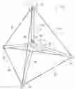
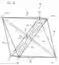
FIG. 1 illustrates a perspective view of a structure constructed in accordance with the teachings of the present disclosure;
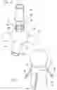
FIG. 2 illustrates an enlarged view of area 2 of FIG. 1;
FIG. 3 illustrates an enlarged view of area 3 of FIG. 1;
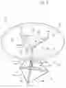
FIG. 4 illustrates a modular structure in the form of a table constructed in accordance with the teachings of the present disclosure;
FIG. 5 illustrates a enlarged fragmentary view of area 5 of FIG. 4;
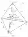
FIG. 6 illustrates a perspective view of an octahedral structure constructed in accordance with the teachings of the present disclosure; and
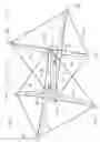
FIG. 7 illustrates another modular structure constructed in accordance with the teachings of the present disclosure.
DETAILED DESCRIPTIONFor the purposes of promoting and understanding the principles disclosed herein, reference will now be made to the preferred embodiments illustrated in the drawings and specific language will be used to describe the same. It will nevertheless be understood that no limitation of the scope is thereby intended. Such alterations and further modifications in the illustrated device and such further applications are the principles disclosed as illustrated therein as being contemplated as would normally occur to one skilled in the art to which this disclosure relates.
In one principal aspect of the present disclosure, a structure includes a hub and a plurality of elongated substantially rigid support members, each rigid support member having a distal end and a proximal end, the proximal end configured to contact an outer surface of the hub. The structure further includes a plurality of elongated substantially flexible support members, each flexible support member configured to couple at least the distal ends of two of the rigid support members. The flexible support members are in tension and the rigid support members are in compression to maintain the structure at equilibrium.
In another principal aspect of the present disclosure, a modular structure includes a plurality of modules. Each module includes a hub and a plurality of elongated substantially rigid support members, each rigid support member having a distal end and a proximal end, the proximal end configured to contact an outer surface of the hub. Each module further includes a plurality of elongated substantially flexible support members, each flexible support member configured to couple at least the distal ends of two of the rigid support members. The flexible support members of each module are in tension and the rigid support members of each module are in compression to maintain the modules at equilibrium. Additionally, each module is coupled to an adjacent module.
In another principal aspect of the present disclosure, a modular structure includes a plurality of modules. Each module includes a spherical hub and a plurality of rigid tubes, each tube having a distal end and a proximal end, the proximal end being in contact with an outer surface of the hub. Each module further includes a plurality of cables, each cable connected to the proximal ends of two adjacent tubes. The adjacent modules share a tube to define a shared tube between each of the adjacent modules, wherein the proximal end of the shared tube is in contact with the hub of one of the adjacent modules and the distal end of the shared tube is in contact with the hub of the other adjacent module. Additionally, the cables of each module are in tension to maintain the proximal ends of the tubes in contact with the outer surface of the corresponding hubs. The proximal end of each shared tube is connected by a cable to the distal ends of the tubes of the adjacent module.
Referring to FIG. 1, a structure 20 constructed in accordance with the teachings of the present disclosure is shown. The structure 20 includes a hub 22, a plurality of elongated rigid support members 24 and a plurality of elongated flexible support members 26. Each rigid support member 24 includes a proximal end 28 and a distal end 30. The proximal end 28 of each rigid support member 24 contacts the hub 22. The distal end 30 of each rigid support member 24 is coupled to the distal end 30 of each adjacent rigid support member 24 with one of the flexible support members 26. The structure 20 is maintained in equilibrium by having the flexible support members 26 being in tension, while the rigid support members 24 are in compression. To maintain the equilibrium, the length of at least one of the rigid support members 24, the length of the flexible support members 26, and/or the size of the hub 22 can be adjusted.
Referring to FIG. 2, the proximal end 28 of each of the rigid support members 24 contacts the hub 22. In other words, the proximal end 28 of each rigid support member 24 simply rests on an outer surface of the hub 22. Because of the tension in the flexible support members 26 and the resulting compression in the rigid support members 24, the proximal end 28 of each rigid support member 24 maintains a frictional contact with the outer surface of the hub 22. Accordingly, the proximal end 28 of each rigid support member 24 is prevented from being disconnected from the outer surface of the hub 22. Should the frictional contact between the proximal end of each rigid support 24 and the outer surface of the hub 22 not be sufficient to securely maintain the proximal end 28 and contact with the hub 22, the length of at least one of the rigid support members 22, the length of the flexible support members 26, and/or the size of the hub 22 can be adjusted to provide sufficient compression between the rigid support member 24 and the hub 22 for a sufficient frictional contact.
A mechanism by which the length of at least one the rigid support members 24 can be adjusted is shown in detail in FIG. 2. At least on of the rigid support members 24 includes a head cap screw 32 that can be mated with a nut 38 and screwed into the proximal end 28 of the rigid support members 24. The head cap screw 32 includes a head 34 that contacts the hub 22. The head cap screw 32 also includes a threaded shaft 36 that can be screwed into the proximal end 28. Accordingly by screwing the head cap screw 32 in and out of the proximal end 28, the total length of the rigid support member 24 can be adjusted by an amount that is substantially equal to the length of the shaft 36. To fix the length of the rigid support member 24 once the head cap screw 32 has been adjusted to a desired length, the securing nut 38 can be turned on the shaft 36 until it abuts the end of the rigid support member 24. Accordingly by tightening the securing nut 38 against the rigid support member 24, the head cap screw 32 is prevented from any movement relative to the rigid support member 24. As shown in FIG. 2, only one of the rigid support members 24 includes the head cap screw 32 and the securing nut 38. However, one of ordinary skill in the art will readily appreciate that any one of the rigid support members 24 or all of the rigid support members 24 can include the head cap screw 32 to maintain the equilibrium of the structure 20.
Referring to FIG. 3, the distal end 30 of one of the rigid support members 24 is shown in detail. Each distal end 30 includes a plurality of apertures 40, through which the flexible support members 26 can be inserted for connection to the distal 30. Each flexible support member 26 may include a hook (not shown) or similar structure at the end thereof so that when it is inserted in the aperture 40 it cannot be removed from the aperture 40. The distal end 30 receives an end cap shaft 42 of an end cap 44. The end cap shaft 42 is sized to frictionally engage an inner surface of the distal end 30 of each of the rigid support members 24. Accordingly, once the end cap shaft 42 is inserted in the distal end 30, it will remain securely connected to the corresponding rigid support member 24. Additionally, the end cap shaft 42 engages the hooked ends (not shown) of the flexible support members 26 to securely connect the flexible support members 26 to the distal end 30 of the rigid support member 24. The end cap 44 is shown to be spherical in FIG. 3. However, the end cap 44 may be in any shape desired to provide the functionality thereof as described herein.
Referring to FIG. 4, the plurality of structures 20 can be joined as will be described in the following to construct a variety of modular structures that can provide a number of functional applications. Referring to FIG. 4, a pair of structures 20 can be joined to provide a table support structure 60 upon which a table top 62 can be placed to construct a table 64. The table support 60 includes a lower structure 70 and an upper structure 72 that are joined together to form the table support structure 60. To illustrate the construction of the table support structure 60, the lower structure 70 and the upper structure 72 are shown to be similar to the structure 20 of FIG. 1. However, the lower structure 70 and the upper structure 72 can be any one of a variety of structures that can be constructed in accordance with the teachings of the present disclosure. The lower structure 70 includes the lower end caps 74 that contact the ground to support the table support structure 60 on the ground. The upper structure 72 includes upper end caps 76 that support the table top 62. The table support structure 60 is maintained in equilibrium as described above. Accordingly, the table support structure 60 provides a stable support structure for the table top 62.
Referring to FIG. 5, the lower structure 70 and the upper structure 72 are similar to the structure 20 in all respects except that the lower structure 70 and the upper structure 72 are joined by a shared rigid support member 80. The shared rigid support member 80 functions as a rigid support member of both the lower structure 70 and the upper structure 72. The shared rigid supported member 80 includes an upper end 82 that contacts the upper hub 22 and the lower end 84 that contacts the lower hub 22. Because the shared rigid support member 80 functions as a component of the upper structure 72 and the lower structure 70, the upper end 82 of the shared rigid support member 80 can be viewed by the upper structure 72 as the proximal end 28 of the shared support member 80. Accordingly, the lower end 84 of the shared support member 80 can be viewed by the upper structure 72 as the distal end 30 of the rigid support member 80. Similarly, relative to the lower structure 70, the upper end 82 can be viewed as the distal end 30 of the shared support member 80 while the lower end 84 can be viewed as the proximal end 28 of the rigid member support member 80. As described above with respect to the structure 20, the distal end 30 of each rigid support member 24 is connected the distal end 30 of an adjacent rigid support member 24 with a flexible support member 26. Therefore, because the lower end 22 of the shared support member 80 can be viewed as the distal end 30 to the upper structure 72, the lower end 84 is connected to adjacent distal ends 30 of the rigid support members 24 of the upper structure 72 by flexible support members 26. Similarly, because the upper end 82 of the shared support member 80 can be viewed by the lower structure 70 as the distal end 30, the upper end 82 is connected to adjacent rigid support members 24 of the lower structure 70 by the flexible support members 26. As shown in FIG. 5, both the lower end 84 and the upper end 82 of the shared support member 80 may include the head cap screw 32 and the securing nut 38 so that the length of the rigid support member 80 can be adjusted as described in the foregoing. Although not necessary, by adjusting the length of the shared support member 80, the table support structure 60 can be maintained in an equilibrium by placing the flexible support member 26 in tension that result in placing the rigid support members 24 including the shared support member 80 in compression against the hubs 22.
In FIGS. 1-5, the structures 20, 70 and 72 were shown to have four rigid support members 24,80. However, a structure can be assembled in accordance with the teachings of the present disclosure so as to have more than four rigid support members to provide any function desired. Referring to FIG. 6, an octahedral structure 100 constructed in accordance with the teachings of the present disclosure is shown. The octahedral structure 100 includes the hub 22 and six rigid support members 24, the distal ends of which are connected by the flexible support members 26. At least one of the rigid support members 24 includes the length adjustment mechanism 32 described above, i.e., the head cap screw 34 and the securing nut 38.
The octahedral structure 100 can serve as a table support structure by placing the lower end caps 102 of the octahedron on the ground and placing a table top (not shown) on the upper end caps 104 of the octahedral structure 100. The octahedral structure 100 is another example of many possible structures that can be constructed in accordance with the teachings of the present disclosure. For example, various geometric structures, such as dodecahedral and icosahedral structures can be constructed in accordance with the teachings of the present disclosure. The octahedral structure 100 or any other geometric structure constructed in accordance with the teachings of the present disclosure can be joined to a number of other adjacent octahedral structures 100 so as to form a truss structure. The truss structure (not shown) can serve as a support beam for any type of structure or even a bridge. Additionally, the plurality of joined octahedral structures 100 or other geometric structures constructed in accordance with the teachings of the present disclosure can be sandwiched by a lower layer and an upper layer (not shown) so as to provide a sandwich support structure for example, such sandwich support structures can be used as walls, floors or ceilings in buildings.
Referring to FIG. 7, yet another support structure 110 constructed in accordance with the teachings of the present disclosure is shown. In the support structure 110 two of the structures 20 are joined together only by a flexible support member 26 of each structure. The support structure 110 includes a first structure 112 and a second structure 114. The end caps of the first structure are shown with reference numbers 116a-116d. Similarly, the end caps of the second structure 114 are shown with reference numbers 118a-118d. As shown in FIG. 7, the distal end of one of the rigid support members 24 of the first structure 112 is connected to one of the flexible support members 26 of the second structure 114, and the distal end of one of the rigid support members 24 of the second structure 114 is connected to one of the flexible support members 26 of the first structure 112. Therefore, the lower structure 112 and the upper structure 114 can be connected together to provide a support structure 110 in yet another principle aspect of the present disclosure. The support structure 110 can be placed between two parallel planes to provide a sandwich structure. The support structure can also be used as a table support structure. When used as a table support structure, the end caps 116a, 116c, 118b and 118d define a plane on which a table top (not shown) can be supported, while end caps 116d, 116b, 118a and 118c define another plane, by which the structure 110 can be supported on the ground. Additionally, by being able to adjust the tension in the flexible support members 26 to result in compression in the rigid support members 24 and the hub 22, if necessary, the support structure 110 can be placed in equilibrium to securely support any structure to which it is attached or any support function for which it is designed.
Although the hub 22 is shown to be spherical in FIGS. 1-7, the hub can be any shape so as to be able to contact the proximal ends 28 of the rigid support members 24 in constructing any one of the exemplary structures disclosed herein or any other structure that is constructed in accordance with the present disclosure. For example, if a structure constructed in accordance with the teachings of the present disclosure is to have only six rigid support members 24, the hub 22 can be a cube so that each side of the cube can contact the proximal end 28 of a rigid support member 24. Such a structure when assembled in accordance with the present disclosure, will resemble a octahedral shaped structure.
The rigid support members can be constructed from rods or tubes. The rigid support members 24 can also be constructed from any material that provides a substantial amount of rigidity. One of ordinary skill in the art will appreciate that all materials have a degree of inherent flexibility. However, the rigid support members 24 should provide enough rigidity so as to be able to be placed in compression to place the structures disclosed here in equilibrium and to function as support structures as described herein. The flexible support members 26 can be wires, cables or stamped sheet metal. Additionally, the flexible support members 26 that are positioned in one plane or face of a geometric structure that is constructed in accordance with the teachings of the present disclosure can be replaced by a piece of fabric. The fabric will be attached to the rigid support members 24 and may be in tension to provide the function of the flexible support members 26. The flexible support members 26 can be constructed from any material so as to provide substantial flexibility while providing the structural support as described herein when placed in tension.
Furthermore, while the particular preferred embodiments have been shown and described, it will be obvious to those skilled in the art that changes and modifications may be made without departing from the teaching of the disclosure. The matter set forth in the foregoing description and accompanying drawings is offered by way of illustration only and not as limitation. The actual scope of the disclosure is intended to be defined in the following claims when viewed in their proper perspective based on the related art.
Claims
What is claimed is:1. A structure comprising:
a hub;
a plurality of elongated substantially rigid support members, each rigid support member having a distal end and a proximal end, the proximal end configured to contact an outer surface of the hub;
a plurality of elongated substantially flexible support members, each flexible support member configured to couple at least the distal ends of two of the rigid support members; and
wherein the flexible support members are in tension and the rigid support members are in compression to maintain the structure at equilibrium.
2. The structure of claim 1, wherein a length of at least one of the rigid support members is adjustable to maintain the structure at equilibrium.
3. The structure of claim 1, wherein lengths of the flexible support members are adjustable to maintain the structure at equilibrium.
4. The structure of claim 1, wherein a size of the hub is adjustable to maintain the structure at equilibrium.
5. The structure of claim 1, wherein the rigid support members are any one of rods and tubes.
6. The structure of claim 1, wherein the flexible support members are any one of wired, cables and stamped sheet metal.
7. The structure of claim 1, wherein the flexible support members in a plane are defined by a fabric covering the plane and being coupled to the corresponding rigid support members.
8. The structure of claim 1, wherein the hub is a sphere.
9. The structure of claim 1, wherein the hub, the rigid support members and the flexible support members define a furniture support structure.
10. A modular structure comprising:
a plurality of modules, each module comprising:
a hub;
a plurality of elongated substantially rigid support members, each rigid support member having a distal end and a proximal end, the proximal end configured to contact an outer surface of the hub; and
a plurality of elongated substantially flexible support members, each flexible support member configured to couple at least the distal ends of two of the rigid support members;
wherein the flexible support members of each module are in tension and the rigid support members of each module are in compression to maintain the modules at equilibrium; and
wherein each module is coupled to an adjacent module.
11. The modular structure of claim 9, wherein the hubs of adjacent modules contact a shared one of the substantially rigid support members.
12. The modular structure of claim 9, wherein the distal end of one of the rigid support members of each module is connected to one of the flexible support members of the adjacent module.
13. The modular structure of claim 9, wherein a length of at least one of the rigid support members of each module is adjustable to maintain the modules at equilibrium.
14. The modular structure of claim 9, wherein lengths of the flexible support members of each module are adjustable to maintain the modules at equilibrium.
15. The modular structure of claim 9, wherein a size of each hub of each module is adjustable to maintain the modules at equilibrium.
16. The modular structure of claim 9, wherein the rigid support members are any one of rods and tubes.
17. The modular structure of claim 9, wherein the flexible support members are any one of wires, cables and stamped sheet metal.
18. The modular structure of claim 9, wherein the flexible support members in a plane are defined by a fabric covering the plane and being coupled to the corresponding rigid support members
19. The modular structure of claim 9, wherein each hub is a sphere.
20. The modular structure of claim 9, further comprising a planar upper support surface, wherein the planar upper support surface is placed on the plurality of modules and supported by the plurality of modules.
21. The modular structure of claim 20, further comprising a planar lower support surface, wherein the planar lower support surface is placed under the plurality of modules to define to support the plurality of modules, and wherein the upper support surface, the plurality of modules and the lower support surface define a sandwich support structure.
22. The modular structure of claim 9, wherein the plurality of modules define a furniture support structure.
23. A modular structure comprising:
a plurality of modules, each module comprising:
a spherical hub;
a plurality of rigid tubes, each tube having a distal end and a proximal end, the proximal end being in contact with an outer surface of the hub; and
a plurality of cables, each cable connected to the proximal ends of two adjacent tubes;
wherein adjacent modules share a tube to define a shared tube between each of the adjacent modules, wherein the proximal end of the shared tube is in contact with the hub of one of the adjacent modules and the distal end of the shared tube is in contact with the hub of the other adjacent module; and
wherein the cables of each module are in tension to maintain the proximal ends of the tubes in contact with the outer surface of the corresponding hubs; and
wherein the proximal end of each shared tube is connected by a cable to the distal ends of the tubes of the adjacent module.
24. The modular structure of claim 23, wherein a length of at least one of the tubes of each module is adjustable to maintain the tension in the cables of each module.
25. The modular structure of claim 23, wherein lengths of the cables of each module are adjustable to maintain the tension in the cables.
26. The modular structure of claim 23, wherein a size of each hub of each module is adjustable to maintain the tension in the cables.
27. The modular structure of claim 23, further comprising planar support surface, wherein the planar support surface is placed on the plurality of modules and supported by the plurality of modules to provide a table top, wherein the plurality of modules and the planar support surface define a table.
28. The modular structure of claim 23, wherein the plurality of modules define a furniture support structure.
Images & Drawings included:

Sources:
- United States Patent and Trademark Office - verify current appl. status at the USPTO↗
Similar patent applications:
- » 20130333310
Modular Structure, Modular Panel To Make Said Modular Structure And Corresponding Method To Make Said Modular Structure - » 20240392567
MODULAR STRUCTURAL COMPONENT, MODULAR STRUCTURAL SYSTEM AND A METHOD OF MANUFACTURING A TENSION ELEMENT AND/OR A COMPRESSION ELEMENT OF A MODULAR STRUCTURAL COMPONENT - » 20180066439
Modular structure, module for such a modular structure and method for the production of such a modular structure - » 20220396925
Underwater modular structure, module of or for said underwater modular structure and method of constructing an underwater modular structure - » 20140190106
Modular structure and said modular structure's structural members made of composite material - » 20130025213
Modular structure and said modular structure's structural members made of composite material - » 20140174009
Modular structure and method of creating modular structures - » 20150237967
Modular technical system for producing a modular-structure foot sole last and modular-structure foot sole last - » 20240167267
MODULAR STRUCTURE AND MAKING PROCESS OF SAID MODULAR STRUCTURE - » 20220082748
Polarizing structure, modular structure, and manufacturing method thereof
Recent applications in this class:
- » 20250171996 2025-05-29
A Variable Orthogrid Stiffened Shell - » 20250122714 2025-04-17
CONNECTOR BRACKET - » 20250003206 2025-01-02
Modular Decking System - » 20240384522 2024-11-21
3D WOVEN STRUCTURES AND METHODS OF MAKING AND USING SAME - » 20240200319 2024-06-20
ROOF PANEL AND ROOF STRUCTURE - » 20240191494 2024-06-13
BRACING ARRANGEMENT - » 20240093479 2024-03-21
INTERWOVEN LATTICE STRUCTURE AND METHOD FOR DESIGNING ULTRA-COMPLIANT INTERWOVEN META-MATERIALS - » 20240084577 2024-03-14
STRUCTURE AND METHOD FOR ERECTING A STRUCTURE - » 20230183964 2023-06-15
Curvature adjustable magnetic strut - » 20230024343 2023-01-26
MODULAR STRUCTURE