Device for transversally cutting a rolled strip
US20060272465A1
2006-12-07
10/560,330
2004-05-25
✅ Patent granted
US 8,047,109 B2
2011-11-01
WO; PCT/EP2004/005582; 20040525
WO; WO2004/110688; 20041223
Phong Nguyen
2024-05-25
Abstract:
The invention relates to a device for transversally cutting a rolled strip using shears, especially drum shears. According to the invention, a gap between the end of the roller table upstream of the shears and the beginning of the roller table downstream of the shears, where there is no support for the rolled strip, is reduced by a pivotable roller table part supporting the rolled strip as it passes through, and a mobile guiding table is arranged between said pivotable roller table part and the beginning of the rear roller table.
Inventors:
- Jurgen Merz 12 🇩🇪 Kreuztal, Germany
- Klaus Bäumer 13 🇩🇪 Kreuztal, Germany
- Jürgen Merz 1 🇩🇪 Llsenburg, Germany
Assignee:
- SMS SIEMAG AKTIENGESELLSCHAFT 184 🇩🇪 Dusseldorf, Germany
Interested in similar patents?
Get notified when new applications in this technology area are published.
Classification:
B23D25/12 » CPC main
Machines or arrangements for shearing stock while the latter is travelling otherwise than in the direction of the cut Shearing machines with blades on coacting rotating drums
B23D33/02 » CPC further
Accessories for shearing machines or shearing devices Arrangements for holding, guiding, and/or feeding work during the operation
B21B2015/0014 » CPC further
Arrangements for performing additional metal-working operations specially combined with or arranged in, or specially adapted for use in connection with, metal-rolling mills; Cutting or shearing the product transversely to the rolling direction
Y10T83/2092 » CPC further
Cutting; With product handling means Means to move, guide, or permit free fall or flight of product
Y10T83/2196 » CPC further
Cutting; With product handling means; Means to move, guide, or permit free fall or flight of product Roller[s]
Y10T83/4728 » CPC further
Cutting; Cutting motion of tool has component in direction of moving work Tool flies by engagement with the work
Y10T83/4734 » CPC further
Cutting; Cutting motion of tool has component in direction of moving work Flying support or guide for work
Y10T83/768 » CPC further
Cutting Rotatable disc tool pair or tool and carrier
B23D19/00 IPC
Shearing machines or shearing devices cutting by rotary discs
B23D25/02 IPC
Machines or arrangements for shearing stock while the latter is travelling otherwise than in the direction of the cut Flying shearing machines
Description
The invention concerns a device for cutting rolled strip to length with a shear, especially a rotary shear, in which a gap between the end of the roller table upstream of the shear and the beginning of the roller table downstream of the shear, where the rolled strip is unsupported, is reduced by a swiveling roller table part that supports the rolled strip as it passes through.
Shears for cutting rolled strip to length in a hot rolling wide strip mill, in a cold-rolling tandem mill, and in hot rolling and cold rolling mills are well known. The use of crank shears and rotary shears is preferred for this purpose. Designs of rotary shears are described, for example, in DE 199 53 906 A1 and in DE 100 01 928 A1.
DE 12 70 368 describes a crank shear for rolled steel in which a conveying roller table has a gap in the area of the cutter circle. A rotating conveying segment that has approximately the width of the cutter and is provided with an approximately semicircularly curved outer surface closes the gap in the conveying roller table when the segment is in its upper position.
A disadvantage of the known designs of a device of this type for cutting rolled strip to length is that, although the distance of the support points/support lines of the rolled strip upstream and downstream of the shear is reduced by a conveying segment that can be rotated in, the rolled strip experiences a deviation from the rolling or conveying direction, depending on the thickness, the surface tension, etc. Due to the greater distances between the support points or lines, the strip flow is disturbed in the device for cutting rolled strip to length. The leading end of the strip reacts very sensitively to these greater distances. The rolled strip can become oriented towards the top or the bottom in this area and can become jammed, e.g., between the conveying segment and the roller table. The equipment has to be shut down. The thinner the rolled strip is, the greater the danger that this will occur.
Therefore, the objective of the invention is to create a device for cutting rolled strip to length which avoids the aforesaid disadvantages.
In accordance with the invention, this objective is achieved by arranging a movable guide table between a swiveling roller table part and the beginning of the downstream roller table. This movable guide table reduces the distance without support points/support lines for the rolled strip in such a way that deviation of the rolled strip is not possible.
It is advantageous if an additional, movable guide table that is interlocked with the swiveling roller table part is arranged between the end of the upstream roller table and the swiveling roller table. The gap in the roller table is then completely closed.
In an advantageous refinement of the invention, the upper drum and the lower drum have flattened surfaces on their outer periphery. This creates a larger opening for the passage of the rolled strip, and during the threading of the rolled strip, the drums, especially the upper drum, do not present obstacles on which the rolled strip is stopped.
It is also advantageous for a movable deflector to be arranged in front of the upper drum. This provides an entry funnel for the rolled strip, thereby preventing upward deviation of the rolled strip.
Additional refinements of the device of the invention are specified in the dependent claims.
A specific embodiment of the invention is described in greater detail below with reference to the highly schematic drawings.
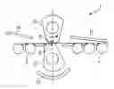
FIG. 1 shows a device for cutting rolled strip to length in the position in which the beginning of the strip is threaded in.
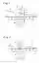
FIG. 2 shows a device according to FIG. 1 in the cutting position.
FIG. 1 shows a device 1 for cutting rolled strip 2 to length with a front roller table 3 and a rear roller table 4. The rolled strip 2 is cut by an upper cutter 5, which is mounted on an upper drum 6, and a lower cutter 7, which is mounted on a lower drum 8. The drums 6, 8 rotate in opposite directions about an upper axis of rotation 9 and a lower axis of rotation 10. The direction of rotation is indicated by arrows 11, 12.
A movable deflector 13 is located above the front roller table 3. A stationary or movable deflector 14 is located above the rear roller table 4.
The drums 6, 8 are rotated in such a way during the threading of the strip that the flattened surfaces 15, 15′, 16, 16′, especially the flattened surface 15 on the upper drum 6, are oriented, together with the movable deflector 13, so as to form an entry funnel.
To ensure that the rolled strip 2, which is supported on the front roller table 3, arrives safely on the rear roller table 4, a swiveling roller table part 17 is rotated into a gap. In this rotation, the swiveling roller table part 17 moves around the lower drum 8. To close the gap completely, movable guide tables 18, 19 are arranged between the swiveling roller table part 17 and the front roller table 3 and between the swiveling roller table part 17 and the rear roller table 4. To close the gap completely, the swiveling roller table part 17 and the movable guide table 18, 19 are interlocked.
FIG. 2 shows the rolled strip 2 and the drums 6, 8 with the cutters 5, 7. The cutters 5, 7 are now positioned in a cutting position. To this end, the upper drum 6 with the upper cutter 5 and the lower drum 8 with the lower cutter 7 are rotated in opposite directions about the upper axis of rotation 9 and the lower axis of rotation 10, respectively. To accomplish this, the swiveling roller table part 17 was rotated out of the gap in the roller table.
To prevent damage to the swiveling roller table 17 by, for example, falling residual pieces of the rolled strip 2, the swiveling roller table part 17 is rotated in such a way that it is covered by the lower drum 8.
In addition, the movable guide tables 18, 19 can avoid the circular arc through which the lower cutter 8 moves. This is accomplished, for example, by a linear lateral movement or a rotational movement.
LIST OF REFERENCE NUMBERS
- 1 cut-to-length device
- 2 rolled strip
- 3 front roller table
- 4 rear roller table
- 5 upper cutter
- 6 upper drum
- 7 lower cutter
- 8 lower drum
- 9 upper axis of rotation
- 10 lower axis of rotation
- 11 direction of rotation of the upper drum
- 12 direction of rotation of the lower drum
- 13 movable deflector
- 14 stationary deflector
- 15, 15′ flattened surface of the upper drum
- 16, 16′ flattened surface of the lower drum
- 17 movable roller table part
- 18 movable guide table
- 19 movable guide table
Claims
1. Device for cutting rolled strip to length with a shear, especially a rotary shear, in which a gap between the end of the roller table upstream of the shear and the beginning of the roller table downstream of the shear, where the rolled strip is unsupported, is reduced by a swiveling roller table part that supports the rolled strip as it passes through, wherein a movable guide table (18) is arranged between a swiveling roller table part (17) and the beginning of the rear roller table (4).
2. Device in accordance with claim 1, wherein a movable guide table (19) is arranged between the end of the front roller table (3) and the swiveling roller table part (17).
3. Device in accordance with claim 1, wherein the outer surface of the swiveling roller table part (17) is engaged with the outer surface of the movable guide table (18, 19).
4. Device in accordance with claim 1, wherein the upper drum (6) and the lower drum (8) have flattened surfaces (15, 15′, 16, 16′) on their outer periphery.
5. Device in accordance with claim 1, wherein a movable deflector (13) is arranged upstream of the upper drum (6).
6. Device in accordance with claim 1, wherein a stationary or movable deflector (14) is arranged downstream of the upper drum (6).
Images & Drawings included:
Sources:
- United States Patent and Trademark Office - verify current appl. status at the USPTO↗
Recent applications in this class:
- » 20240399476 2024-12-05
CUTTING DEVICE FOR CUTTING FLAT METAL PRODUCTS AND CUTTING SHEAR FOR CUTTING SAID FLAT METAL PRODUCTS EQUIPPED WITH SAID DEVICE - » 20210220929 2021-07-22
Device and method for cooling a cross-cutting shear in hot strip mills - » 20170341163 2017-11-30
Battery plate cutter system and method - » 20120198978 2012-08-09
SHEARING SYSTEM FOR MOVING PRODUCT - » 20120192676 2012-08-02
Dual ratio shearing system - » 20110017039 2011-01-27
Drum Shear Arrangement - » 20110017038 2011-01-27
Rotary shear - » 20060278054 2006-12-14
Dual ratio drive for rotary shear - » 20050183557 2005-08-25
Method of operating a flying shear
Recent applications for this Assignee:
- » 20150321270 2015-11-12
CO-MOVING HYDRAULIC SHEARS WITHOUT STAND - » 20150027185 2015-01-29
APPARATUS FOR STRAIGHTENING METAL STRIP - » 20150007663 2015-01-08
DETECTION DEVICE FOR METAL STRIPS OR PLATES - » 20150000861 2015-01-01
Method for the continuous casting of a metal strand in a continuous casting installation and a continuous casting installation - » 20140327192 2014-11-06
METHOD FOR OPERATING AN OXYGEN BLOWING LANCE IN A METALLURGICAL VESSEL AND A MEASUREMENT SYSTEM FOR DETERMINING A MEASUREMENT SIGNAL USED IN THE METHOD - » 20140060135 2014-03-06
METHOD AND DEVICE FOR LUBRICATING ROLLERS AND A ROLLED STRIP OF A ROLLING STAND - » 20130145914 2013-06-13
CRANK SCISSORS HAVING TWO PAIRS OF BLADES FOR CUTITNG ROLLING STRIPS - » 20130119168 2013-05-16
ULTRASONIC NOZZLE FOR USE IN METALLURGICAL INSTALLATIONS AND METHOD FOR DIMENSIONING A ULTRASONIC NOZZLE - » 20130106034 2013-05-02
Device for injecting gas into a metallurgical vessel - » 20130098736 2013-04-25
TRANSPORT DEVICE FOR SLABS, COMPRISING AT LEAST TWO LINEAR CONVEYING SECTIONS WHICH CAN PIVOT INDEPENDENTLY OF EACH OTHER