Mounting unit of wall faucet
US20060272708A1
2006-12-07
11/143,613
2005-06-03
✅ Patent granted
US 7,159,609 B2
2007-01-09
-
-
Eric Keasel
2025-06-03
Abstract:
An improved mounting unit of wall faucet mainly is to design two locking ends extruded on the shutter near the granite counter to lock the locking units and position the water faucet on the granite counter; in addition, the locking ends are designed on the non-returning pads in the locking screw caps to prevent the water flow from effusion from the locking units. Therefore, because the locking units are locked directly on the locking ends of the water faucet and the water flow can directly flow from the locking screw caps of the locking units and inner thread portion vertically, so as to shorten the interval between the shutter and wall after the installation of water faucet into the shutter of a granite counter for saving space and costs in connection materials.
Interested in similar patents?
Get notified when new applications in this technology area are published.
Classification:
F16L5/00 IPC
Devices for use where pipes, cables or protective tubing pass through walls or partitions
E03C1/042 » CPC main
Domestic plumbing installations for fresh water or waste water; Sinks; Plumbing installations for fresh water; Water-basin installations specially adapted to wash-basins or baths Arrangements on taps for wash-basins or baths for connecting to the wall
Y10T137/698 » CPC further
Fluid handling; With casing, support, protector or static constructional installations; Static constructional installations; Buildings Wall
Y10T137/9464 » CPC further
Fluid handling Faucets and spouts
E03C1/04 IPC
Domestic plumbing installations for fresh water or waste water; Sinks; Plumbing installations for fresh water Water-basin installations specially adapted to wash-basins or baths
Description
BACKGROUND OF THE INVENTION1) Field of the Invention
An improved mounting unit of wall faucet, in which two locking units are designed on the locking ends of the water faucet, and the water flow can directly flow from locking screw caps of the locking units and inner thread portion vertically, so as to shorten the interval between the shutter and wall after the installation of water faucet into the shutter of a granite counter for saving space and costs in connection materials.
2) Description of the Prior Art
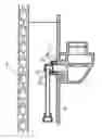
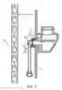
The present invention mainly relates to an unit, after the completion of pipeline establishment, to connect the pipeline from the rear of the granite counter in the case of adding a water faucet on the counter, for the impossibility to make another pipeline; Generally, referring to the FIG. 1, the water faucet 5 is assembled through locking end of the shutter S of the granite counter and extrudes into the rear end of the shutter. In addition, because the part of the locking end 51 into the shutter is too long, it results in a big interval L1 of the shutter away the wall after the installation of feed pipe 6. Not only are the materials wasted, but also is the space occupied besides some deficiencies in use.
SUMMARY OF THE INVENTIONThe improved mounting unit of wall faucet the present invention provides mainly is to design two locking ends extruded on the shutter near the granite counter to lock the locking units and position the water faucet on the granite counter; in addition, the locking ends are designed on the non-returning pads in the locking screw caps to prevent the water flow from effusion from the locking units. Therefore, because the locking units are locked directly on the locking ends of the water faucet and the water flow can directly flow from the locking screw caps of the locking units and inner thread portion vertically, so as to shorten the interval between the shutter and wall after the installation of water faucet into the shutter of a granite counter for saving space and costs in connection materials.
BRIEF DESCRIPTION OF THE DRAWINGSFIG. 1 is the plane cutaway view of the prior art.
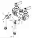
FIG. 2 is the three-dimensional exploded view of the present invention.
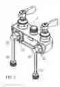
FIG. 3 is the three-dimensional combination diagram of the present invention.
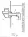
FIG. 4 is the plane cutaway view of the present invention.
DETAILED DESCRIPTION OF THE PREFERRED EMBODIMENTSReferring to the FIG. 2˜FIG. 4, the unit of the present invention can be saw clearly, mainly is to design two locking ends 11 on the shutter S of the granite counter, which extrudes from the shutter S to lock the locking units 2 and position the water faucet Ion the shutter S;
The locking unit 2 is composed of a locking screw cap 21 locked on the locking end 11 of the water faucet, a non-returning pad 22 in the locking screw cap 21 and a feed pipe 23 extruded from the end of the locking screw cap 21; in which:
The locking end 11 of the water faucet is designed on the non-returning pads 22 in the locking screw cap 21 after the locking screw cap 21 is locked on the locking end 11 of the water faucet 1 to prevent the water's effusion from the locking ends 11;
A ladder-shaped empty inner thread portion 24 is designed at the top end of the feed pipe 23, whose smaller ring-shaped surface end 241 goes through the locking screw cap 1 in advance, and then is interlinked with the feed pipe 23 connected to the inner thread portion 24 fixed on the base; additionally, the outer diameter of the inner thread portion 24 is less than the perforation diameter of the locking screw cap 21, so that the inner thread portion 24 can turn in the locking screw cap 21 to make the feed pipe 23 wiggly and aiming at the outlet pipeline properly after going through the locking screw cap 21;
Referring to FIG. 4, the water can directly flow through the locking screw cap 21 and inner thread portion 24 vertically after flowing through the locking end 11 of the water faucet 1. Therefore, because the locking units 2 are locked directly on the locking ends 11 of the water faucet 1 and the water flow can directly flow from the locking screw caps 21 of the locking units 2 and inner thread portion 24 vertically, so as to shorten the interval L between the shutter S and wall W after the installation of water faucet 1 into the shutter S of the granite counter for saving space and costs in consumptive materials.
Claims
1. (canceled)
2. A wall faucet assembly for a shutter of a granite counter top comprising:
a) a faucet having two locking units extending through the shutter; and
b) a locking unit having:
I) two locking screw caps, one of the two locking screw caps is threadedly connected to each of the two locking units;
ii) two non-return pads, one of the two non-return pads is located between one of the two locking screw caps and each of the two locking units;
iii) two connector portions, each of the two connector portions has a ring portion located on an outer periphery of a first end thereof, one of the two connector portions is inserted through a hollow interior of each of the two locking screw caps and retained therein by the ring portion; and
iv) two feed pipes, one of the two feed pipes extends outwardly from a second end of each of the two connector portions.
3. The wall faucet assembly according to claim 2, wherein the two locking units of the faucet extend through the shutter.
4. The wall faucet assembly according to claim 2, wherein the shutter is located between the two locking units and the two locking screw caps.
Images & Drawings included:
Sources:
- United States Patent and Trademark Office - verify current appl. status at the USPTO↗
Recent applications in this class:
- » 20230332386 2023-10-19
WATER CONVEYANCE IMPLEMENT - » 20230228071 2023-07-20
METHOD OF MODIFYING A FLUID SUPPLY FEATURE - » 20220396935 2022-12-15
Adjustable fluidic coupling - » 20220120062 2022-04-21
ESCUTCHEON - » 20200232196 2020-07-23
System and method for pipe stabilization - » 20190338500 2019-11-07
Flush mounted built-in body for a sanitary fitting with at least one push button which can be variably positioned - » 20190085540 2019-03-21
SHOWER APPARATUS - » 20190085539 2019-03-21
In-wall valve body for shower or bathtub - » 20180340317 2018-11-29
Fitting mount with adapter element and vehicle washroom and vehicle with a fitting mount - » 20180291597 2018-10-11
Mounting devices and methods for exterior faucets and lines