Shield apparatus and methods of use
US20060273113A1
2006-12-07
11/144,979
2005-06-03
Abstract:
A shield apparatus for use with a mechanism including a reservoir for distribution of an extrudable substance such as an adhesive. The invention includes a body which extends along an axis. The body defines a concave recess which can contain at least some of the extrudable substance that is intended to be extruded when the body portion of the apparatus is inverted.
Interested in similar patents?
Get notified when new applications in this technology area are published.
Classification:
B05C17/00516 » CPC main
Hand tools or apparatus using hand held tools, for applying liquids or other fluent materials to, for spreading applied liquids or other fluent materials on, or for partially removing applied liquids or other fluent materials from, surfaces for discharging material through an outlet orifice by pressure; Details of the outlet element Shape or geometry of the outlet orifice or the outlet element
B65D88/54 IPC
Large containers characterised by means facilitating filling or emptying
Description
TECHNICAL FIELDThe present invention relates to a shield apparatus for use in dispensing a substance or material and methods of using the apparatus. For example, without limitation, an exemplary embodiment of the present invention relates to an apparatus, attachable to a pressure gun, for use in preventing an extrudable substance from coming into contact with a surface area with which such contact is not desirable.
BACKGROUND OF THE INVENTIONIn everyday life, whether in our professional or our personal lives, we use applicators for applying a myriad of different substances. Some of these substances are liquids having a low viscosity and which are readily pourable. Other substances have a much higher viscosity and thus are not readily pourable. Such substances include caulks, greases, sealants, coatings, adhesives (e.g., construction adhesives), glues (e.g., horticulture glue), artists' oils, pastes, certain foods or food ingredients, and similar flowable substances used in various activities. Although not dry, such substances have a higher viscosity and are more aptly described using terms such as moist, sticky, pasty, gelatinous or gooey. These substances may or may not be chemically reactive with other substances or materials with which they come into contact during or after their intended application or use.
Applicator systems used to apply a substance having a higher viscosity (hereinafter referred to as “substance”) typically use an arrangement wherein the volume of the substance in a tube, canister or other container holding the substance is compressed to create a sufficient pressure to force the substance through an outlet defined in the container. Such an applicator system is herein referred to as a “pressure gun”. Examples of such systems are a caulk gun and a caulk tube having a plunger-like back end, a grease gun having a chamber in which a substance can be compressed, and a toothpaste-like tube that is able to compress a substance by rolling up the back end with a pin or key. These applicator systems typically include a plenum filled with the substance; a mechanism for compressing the volume of the substance within the container; an egress nozzle or spout extending from the container and used to direct and control the flow of the substance being extruded from the container; and, in some instances, an adaptor to modify the flow pattern of the substance being extruded. It will be understood that, when air becomes caught in a flow of the substance, the air may cause the substance to splatter as it is being extruded.
To attain the desired direction and substantial uniformity of flow, it is often necessary to apply a force that creates a pressure on the substance that is greater than a flow initiation pressure. Thus, even after the force is greatly reduced or even completely removed, because the volume of the container cannot be re-expanded quickly enough to diminish the pressure, there is a period of time during which the pressure on the substance is greater than that at which the substance will cease flowing. Consequently, an excess of the substance is extruded. There may be other causes of undesired extrusion and undesirable side-effects. In interior construction work, many adhesives are applied to workpieces such as baseboard by extrusion from caulk tubes using a caulk gun. Often a floor surface adjacent where the baseboard is being installed has already been completed with a finished surface such as newly laid carpeting, parquet flooring or linoleum. Not only is it time consuming and expensive to clean-up adhesive that comes into contact with the finished surface, but the adhesive may be difficult to remove or may need to be chemically treated to effect removal. Thus, it is desirable to be able to effectively apply the adhesive in a safe and efficient manner. These concerns are equally applicable to other situations as well (i.e., where it is necessary to be able to apply a substance to a surface in an ambient environment that must remain free of excess substance).
SUMMARY OF THE INVENTIONThe present invention is an apparatus for use in combination with a reservoir for accommodating a flowable substance, such as an adhesive. The reservoir is provided with an outlet through which the substance can be extruded. The apparatus includes a body which extends along an axis between front and back ends thereof. The body also defines upper and lower surfaces thereof. The body is so constructed such that a shield portion of the body encompasses at least a part of the substance extrudable through the reservoir outlet. In a preferred embodiment, the body defines a concave recess which extends outwardly from the shield portion of the body. The recess serves to contain some of the substance that is extruded from the reservoir along the lower surface of the body when the apparatus is inverted, or when the lower surface would not accommodate the substance otherwise. Finally, the apparatus includes means for attaching the body to the reservoir.
In a preferred embodiment, the body defines a channel which extends along the axis of the body. Such a channel is formed at the front end of the body.
In a preferred embodiment, the apparatus further includes left side and right side baffles. Such baffles are spaced from one another at a distance to allow said baffles to accommodate a workpiece therebetween.
In certain embodiments, the body of the apparatus is transparent. This allows a user of the implement to observe substance flow.
In certain embodiments, the means by which the body is attached to the reservoir can be in the form of a manifold. Such a manifold allows substance distribution. In a case where the substance is an adhesive, more adequate adhesive coverage can be achieved.
The present invention is thus a shield apparatus for use with a reservoir having an outlet through which a substance is extrudable. More specific features and advantages obtained in view of those features will become apparent with reference to the DETAILED DESCRIPTION OF THE INVENTION, appended claims and accompanying drawing figures.
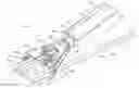
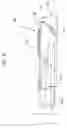
BRIEF DESCRIPTION OF THE FIGURESFIG. 1 is a perspective view of a shield apparatus in accordance with the present invention;
FIG. 2 is a top plan view of the shield apparatus of FIG. 1;
FIG. 3 is a bottom plan view of the shield apparatus of FIG. 1;
FIG. 4 is a side elevational view of the shield apparatus of FIG. 1;
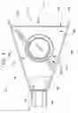
FIG. 5 is a front elevational view of the shield apparatus of FIG. 1;
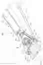
FIG. 6 is a side elevational view of an exemplary embodiment of a shield apparatus with an adaptor manifold of a pressure gun seated therein; and
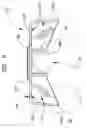
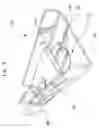
FIG. 7 is a perspective view of the shield apparatus of FIG. 6 after being inverted and with an adaptor manifold of a pressure gun seated therein.
DETAILED DESCRIPTION OF THE INVENTIONThe present invention relates to a shield apparatus and using the apparatus with a pressure gun. In the following detailed description of exemplary embodiments of the present invention, references are made to the accompanying figures, which figures form a part hereof and in which are shown by way of illustration specific embodiments in which the invention may be practiced. Although exemplary embodiments have been described herein, it should be recognized that other embodiments and numerous changes and variations to embodiments can be made without departing from the scope of the present invention as recited in the claims.
One or more embodiments of the shield apparatus may provide one or more of the following advantages: At least in one embodiment, the shield apparatus is configured for use in preventing at least some of a substance from coming into contact with structure in an ambient environment, i.e., to contain at least splashing, splattering and/or other spillage of the substance during and after applying the substance to a workpiece. This containment can reduce the amount of clean-up work after a project, which can be expensive in trades such as interior construction.
At least in one embodiment, a portion of the shield apparatus is transparent so that a user can view a workpiece though the apparatus and thus better control a work process.
At least in one embodiment, the shield apparatus is configured so that the side baffles of the apparatus act as guides to translate a pressure gun along a surface of a workpiece while a substance is being applied, thus minimizing having to rework parts of the application.
At least in one embodiment, the shield portion is fabricated from a material to which many substances normally do not bond so that the apparatus is easily cleaned up by chipping or peeling.
At least in one embodiment, the shield apparatus can be at least partially disassembled so that a component that may wear out faster than other components can be readily replaced.
Although the above-described advantages of the shield apparatus and methods of using the shield apparatus have made reference to interior construction, many of these advantages are also available when other embodiments of the shield apparatus are used in other activities. For example, a shield apparatus also may be used in exterior construction processes (e.g., caulking), mechanic tasks (e.g., greasing), maintenance tasks, horticultural activities (e.g., glue banding trees), agricultural activities, creating visual art, and food preparation.
As shown in FIG. 1, an environment in which an embodiment of a shield apparatus may be utilized is interior building or dwelling construction, such as a process of installing baseboard along walls. A simplified depiction of a typical construction environment includes a clean or finished surface (not shown) upon which a workpiece such as a baseboard 14, having a left edge 16A and a right edge 16B, is laid. Typically, a pressure instrument 20 includes a caulk gun 30 and a caulk tube 22, having a front end 24 and a back end, in which an adhesive 36 is stored. The caulk gun 30 is used to apply a force to the back end of the caulk tube 22 to cause the adhesive 36 to flow through a nozzle 28 on the front end 24 of the caulk tube 22 and onto the back surface 18 of the baseboard 14.
The instrument 20 also can include an adaptor manifold 32 that fits over the nozzle 28 to create a certain flow pattern (e.g., three beads of adhesive instead of one) or bead size. Those skilled in the art should be aware that there are various kinds of adaptors available to create different flow patterns and/or different bead sizes. When a manifold 32 is used, one or more outlets 34 through which the adhesive 36 is applied are defined as being in communication with the nozzle 28.
The embodiment of the shield apparatus 50 shown in FIG. 1 attaches to the adaptor manifold 32 by seating the adaptor manifold 32 in a resilient plastic collar 88. Associated with this collar 88 via a living hinge 94 is a body 52 of the apparatus 20. Body 52 has a front end 56, a back end 58, an upper surface 60, a lower surface 62, a left side baffle 64A and a right side baffle 64B. Since the front end 56 of the shield apparatus 50 extends outwardly in front of the pressure gun outlet 34, the living hinge 94 can be used to allow the shield apparatus 50 to flex or bend so that the front end 56 of the shield apparatus 50 and the pressure gun outlet 34 can be simultaneously positioned adjacent to the baseboard 14 while the adhesive 36 is being applied.
The left side baffle 64A and the right side baffle 64B of the shield apparatus 50 are spaced by a distance to allow at least a part of each baffle 64A, 64B to be positioned adjacent to a corresponding side of the baseboard 14. Then, at least a part of the baffles 64A, 64B may be used to guide the pressure gun 20 along the baseboard 14 while the adhesive 36 is being applied. At the same time, at least a portion of the body 52 forms a shield portion 76 that at least partially encompasses the pressure gun outlet 34 for use in preventing splatters, splashes and/or other spillages from coming into contact with the clean surface 12.
As shown in FIG. 7, at times when an application is temporarily halted or when it is completed, the pressure gun and shield apparatus 250 together can be inverted, or the collar 288 of the shield apparatus 250 can be rotated around the adapter manifold 232 to invert the shield apparatus 250. When the shield apparatus 250 is inverted, the lower surface 262 of the body 252 can catch any excess adhesive that continues to flow or otherwise spill from the pressure gun outlet 234. At least one concavity 282 defined by the body 252 is configured to contain at least some of the adhesive on the lower surface 262 of the body 252.
FIGS. 2-5 show various views of an embodiment of a shield apparatus. FIG. 2 is a top view of the shield apparatus that illustrates its overall shape and a concavity. FIG. 3 is a bottom view of the shield apparatus that illustrates its overall shape and a collar. FIG. 4 is a (right) side view of the shield apparatus that illustrates its overall shape and the relative positions of the concave recess and the collar. And FIG. 5 is a front view of the shield apparatus that illustrates its overall shape and a configuration of the collar.
The shield apparatus 150 shown in FIGS. 2-5 includes a body 152 and an attaching arrangement 188 in association with the body 152. In at least one embodiment, the association 190 is a rigid connection between the body 152 and the attaching arrangement 188, and in at least another embodiment, the association 190 is a flexible connection (including hinged connections). Preferably, a living hinge 194 is used in connecting the attaching arrangement 188 and the body 152. The flexible connection is used to allow the shield apparatus 150 to bend, so that the shield apparatus 150 is adaptable to allow the front end 156 of the body 152 and a pressure gun outlet (not shown), to which the shield apparatus 150 is attached, to be simultaneously positioned adjacent a workpiece.
In at least one embodiment, the attaching arrangement 188 is integral with the body 152. Preferably, the body 152 and the attaching arrangement 188 are formed separately, in which case the body 152 and the attaching arrangement may be either directly connected to one another or indirectly connected (e.g., via a thin strip of material such as plastic) to one another. When the body 152 and the attaching arrangement 188 are formed separately, the association 190 also may be either a permanent or a temporary adjoining. Examples of the former are chemical bonding, thermal bonding, and rivets. Examples of the latter are threaded devices, Velcro, clasps, and various frictional fits. In at least one embodiment where the association 190 is a temporary adjoining, the shield apparatus 150 may be readily (i.e., with a small effort and without causing damage) disassembled so that either the body 152 or the attaching arrangement 188 may be replaced when it becomes worn out or damaged, or may be interchanged with a similar component meeting different dimensional requirements.
The attaching arrangement 188 is used to attach the shield apparatus 150 to a pressure gun (not shown). The attaching arrangement 188 typically is positioned proximate to the back end 158 of the body 152 and comprises an arrangement such as a resilient plastic collar, a resilient rubber collar, a threaded clamp, a compression clamp, a strap, Velcro or a clasp. Since the shield apparatus 150 may be attached to any available part of a pressure gun, such as an adaptor manifold 232 as shown in FIGS. 6-7, those skilled in the art should be aware that a myriad of arrangements and configurations are possible. Further, those skilled in the art also should be aware that the attaching arrangement may be integral with at least part of an adaptor manifold or other available component of a pressure gun, in which case the arrangement may be an extension of the component or part of the component itself.
The body 152 extends along a longitudinal axis (not shown) thereof between a front end 156 and a back end 158 of the body 152, wherein the body 152 defines an upper surface 160, a lower surface 162, a left side baffle 164A and a right side baffle 164B. The body 152 is configured to allow at least part of a pressure gun outlet, and preferably all of the pressure gun outlet, to be at least partially encompassed, and preferably at least substantially encompassed (i.e., almost all except for possibly areas near the sides of the outlet) from above the outlet, by a shield portion 176 of the body 152. The shape of the shield portion 176 may range anywhere from a partial bubble-like or curvilinear shape to a lid with drop-down sides. Those skilled in the art should be aware that many different shapes are suitable for use in preventing splatters, splashes and/or other spillages of a substance being extruded from a pressure gun from coming into contact with structure in the ambient environment. The shield portion 176 is typically positioned proximate to the front end 156 of the body 152. Preferably, the shield portion 176 and other portions of the body 152 are fabricated from an acrylic plastic so that many substances that may come into contact with these portions are easily removed, such as by chipping or peeling.
The body 152 is configured to form a channel 170 that extends along the longitudinal axis of the body 152. One end 172 of the channel 170 coincides with the front end 156 of the body 152, and the channel extends at least past where a pressure gun outlet is positionable, so that the body 152 does not interfere with an application of a substance being extruded from a pressure gun.
The left side baffle 164A and the right side baffle 164B of the shield apparatus 150 are spaced by a predetermined distance to allow at least part of each side baffle 164A, 164B to be positioned adjacent to a corresponding side of a workpiece. Thus, at least a part of the side baffles 164A, 164B can be used to guide a pressure gun along a workpiece to more efficiently apply a substance being extruded from a pressure gun. Preferably, this distance is approximately equal to a width of a stock workpiece, such as a stock baseboard. Furthermore, the body 152 has at least a transparent portion 174 which may include up to the entire body 152, configured so that a user of the shield apparatus 150 can view an area of a workpiece to which a substance is being applied.
Further, the body 152 is configured to form at least one concave recess 182 that extends outwardly from the upper surface 160 of the body 152. The concavity 182 is configured to receive at least some of a substance that is deposited on the lower surface 262 of the body 252 at times when the shield apparatus 150 is inverted. The at least one concave recess 182 is a centrally-configured, circular indentation in the body 152 and includes only a portion of the body 152. However, those skilled in the art should be aware that numerous shapes and configurations are possible. For example, in other embodiments, the concavity 182 spans the entire body 152. In at least another embodiment, the concavity 182 comprises multiple indentations, and in still at least another embodiment, the concavity 182 extends from one side baffle 164A or 164B of the body 152 to the other side 164B or 164A, respectively. Further still, in at least another embodiment, the concavity 182 is formed by using one or more structures such as a wall, a ridge or a rib that extends from the body 152. Preferably, the concavity 182 is configured to allow at least part of a pressure gun outlet to be positioned over at least a portion of the concavity 182 at times when the shield apparatus is inverted.
FIGS. 6-7 show an adaptor manifold 232 positioned and seated in another embodiment of the shield apparatus 250. FIG. 6 is a view showing the relative positioning of the adaptor manifold 232 in relation to the body 252 and the concavity 282; and FIG. 7 is a view showing the shield apparatus 250 and the adaptor manifold 232 in an inverted position. The shield apparatus 252 is invertible by rotating together the shield apparatus 252 and at least the component of the pressure gun to which the shield apparatus 252 is attached so that excess substance that is extruded from the pressure gun is deposited on the lower surface 262 of the body 252. The concavity 282 can then be used to contain at least some of the deposited substance on the lower surface 262. Alternatively, the shield apparatus 250 is invertible by rotating it separately from any of the components of a pressure gun.
In operation, a pressure gun 20 having an outlet 34 for extruding a substance 32 and a shield apparatus 50 comprising a body 52 having a front end 56, a left side baffle 64A and a right side baffle 64B are provided. At times when the substance 32 is being applied from the pressure gun 20 to a workpiece 14, the front end 56 of the body 52 and the pressure gun outlet 34 are simultaneously positioned adjacent to a surface 18 of the workpiece 14 to allow the shield apparatus 50 to at least partially encompass at least part of the pressure gun outlet 34. At times when the application process is either temporarily halted or is completed, the shield apparatus 50 is inverted to collect and contain excess flow of the substance 32.
During the application of the substance 32, the workpiece 14 can be viewed through the shield apparatus 50. Thus, an application can be completed more efficiently and more precisely because a point of application can be seen by a user of the pressure gun 20 and shield apparatus 50. The shield apparatus 50 is bendable to allow the front end 56 of the body 52 and the pressure gun outlet 34 to be simultaneously positioned adjacent to the workpiece 14 at times when some of the substance is being applied to the workpiece 14. Further, side baffles 64A, 64B of the shield apparatus 50 are spaced by a distance to allow at least part of each side baffle 64A, 64B to be positioned adjacent to a corresponding side of the workpiece 14 to contain the substance 32 as it is being applied and/or so that a part of the side baffles 64A, 64B can act as guides as the pressure gun 20 moves along the workpiece 14.
The shield apparatus 50 can be at least partially disassembled such as by removing a threaded device such as a bolt or screw, pulling Velcro apart, unhooking a clasp, or separating a frictional fit, so that the body 52 and the attaching arrangement 88 are separable. Thus, either the body 52 or the attaching arrangement 88 can be replaced when it is worn out or damaged, without replacing the entire shield apparatus 50, or can be interchanged with another like component that meets different dimensional needs or requirements.
Claims
That which is claimed:1. A shield apparatus for use with a reservoir having an outlet through which a substance is extrudable, comprising:
a body extending along an axis between a front end and a back end, the body having an upper surface and a lower surface;
the body allowing at least part of the substance extrudable through the reservoir outlet to be encompassed by a shield portion of the body;
wherein the body defines a concave recess extending outwardly from the shield portion; and
wherein the recess contains at least some of the substance that is unintendedly extruded from the reservoir along the lower surface of the body; and
means for attaching the body to the reservoir.
2. The shield apparatus of claim 1 wherein the body defines a channel extending along the axis of the body, and wherein an end of the channel is formed by the front end of the body.
3. The shield apparatus of claim 1 wherein the body further comprises left side and right side baffles spaced at a distance to allow at least part of each side baffle to be positioned adjacent a corresponding edge of a workpiece.
4. The shield apparatus of claim 1 wherein at least a portion of the body is transparent.
5. The shield apparatus of claim 1 wherein the shield portion of the body defines the front end of the body.
6. The shield apparatus of claim 1 wherein the recess is configured to allow at least part of the reservoir outlet to be positioned above the recess at times when the shield apparatus is inverted.
7. The shield apparatus of claim 1 wherein the body of material further comprises a left side baffle and a right side baffle and wherein the recess extends between the side baffles of the body.
8. The shield apparatus of claim 1 wherein the means for attaching comprises a resilient collar and a clamp.
9. The shield apparatus of claim 1 wherein the means for attaching is configured to attach to a manifold.
10. The shield apparatus of claim 1 wherein the body and the means for attaching are flexibly connected.
11. The shield apparatus of claim 10 wherein a living hinge is used in connecting the body and the means for attaching.
12. A shield apparatus for use with a caulk gun, a caulk tube, and an adaptor manifold having an outlet through which a substance is extrudable, comprising:
a body extending along a longitudinal axis between a front end and a back end, the body comprising an upper surface and a lower surface;
the body being configured to allow the adaptor manifold outlet to be substantially encompassed by a shield portion of the body;
wherein the body defines at least one concavity extending outwardly from the upper surface of the body; and
wherein the concavity is configured to accommodate extrudable substance extruded through the adaptor manifold outlet at times when the shield apparatus is inverted; and
means for attaching the shield apparatus to the adaptor manifold.
Images & Drawings included:


Sources:
- United States Patent and Trademark Office - verify current appl. status at the USPTO↗
Similar patent applications:
- » 20200348700
Weld shielding apparatus and method of use by controlling shielding gas timing relative to welding - » 20240298433
ELECTROMAGNETIC WAVE SHIELDING MATERIAL, ELECTRONIC COMPONENT, ELECTRONIC APPARATUS, AND USING METHOD FOR ELECTROMAGNETIC WAVE SHIELDING MATERIAL - » 20080084958
NEUTRON SHIELDING RING, APPARATUS AND METHOD USING THE SAME FOR STORING HIGH LEVEL RADIOACTIVE WASTE - » 20180157278
Weld shielding apparatus and method of use - » 20060266745
Gas shielding apparatus and method of use - » 20200217910
Continuous scanning method using signal shielding and apparatus for the same - » 20150287489
Neutron shielding ring, apparatus and method using the same for storing high level radioactive waste - » 20200044332
Apparatus and methods for electromagnetic shielding using an outer cobalt layer - » 20140204440
Light shielding apparatus using magnetic microbeads and method of the same - » 20080096494
Method and apparatus for using an electromagnetically shielded enclosure for exchanging secure data
Recent applications in this class:
- » 20250065361 2025-02-27
SEALANT FORMING NOZZLE, SEALANT FORMING APPARATUS, AND SEALANT FORMING METHOD - » 20250010328 2025-01-09
ADJUSTABLE FLUID NOZZLE AND APPARATUS INCLUDING SAME - » 20240408640 2024-12-12
LIQUID SEALANT DISPENSER TIP - » 20240246112 2024-07-25
COMPOSITION APPLICATOR TIP AND INSTRUMENTATION - » 20240238835 2024-07-18
CAULK RESHAPING TOOL - » 20240123465 2024-04-18
Paste-like medium applicator - » 20230338983 2023-10-26
Application device and method for producing an application device - » 20230021542 2023-01-26
Adjustable fluid nozzle and apparatus including same - » 20220395853 2022-12-15
Caulk reshaping tool - » 20220305520 2022-09-29
Medical lubricant applicator