Sliding track structure
US20060273704A1
2006-12-07
11/143,439
2005-06-03
Abstract:
A sliding track structure is installed on one side of a server to guide loading of the server into a rack. The sliding track structure includes a body which has a latch hook, extended from a bottom side into the interior of the server to be latched thereon. The body, further, has an upright elastic rib extended from the top surface and a transverse elastic rib extended from a lateral side, to press respectively an inner top wall and an inner side wall of the rack to cushion the external impact and provide a buffer and shock absorbing effect horizontal and vertical direction.
Interested in similar patents?
Get notified when new applications in this technology area are published.
Classification:
G11B33/127 » CPC main
Constructional parts, details or accessories not provided for in the other groups of this subclass; Disposition of constructional parts in the apparatus, e.g. of power supply, of modules the apparatus comprising a plurality of recording/reproducing devices, e.g. modular arrangements, arrays of disc drives Mounting arrangements of constructional parts onto a chassis
G11B33/123 » CPC further
Constructional parts, details or accessories not provided for in the other groups of this subclass; Disposition of constructional parts in the apparatus, e.g. of power supply, of modules the apparatus comprising a single recording/reproducing device Mounting arrangements of constructional parts onto a chassis
A47B88/00 IPC
Details of furniture
A47B88/00 IPC
Drawers for tables, cabinets or like furniture; Guides for drawers
Description
FIELD OF THE INVENTIONThe present invention relates to a sliding track structure adopted for use on servers and particularly to a sliding track structure that provides a buffer and shock absorbing function in horizontal and vertical direction.
BACKGROUND OF THE INVENTIONWith the constant advance of technology, computer application is no longer limited to a few national research institutions and known large enterprises. These days the price of the computer is very low and is affordable to almost every one.
Based on the application, the computer generally can be categorized in personal computer, server and workstation, and super computer. The personal computer usually has one to two processors. It generally is used for processing administrative tasks in the enterprises or multimedia entertainment related applications. To process more complex tasks such as 3D computer graphic applications, the server is more desirable. To meet the present network requirements, users generally select a server computer system which consists of two to four processors, some even have eight or sixteen processors. For some specialized applications that require very high performance, such as hydrogen bomb simulation, weather forecast and simulation, gene engineering and the like, thousands or even hundreds or thousands of processors (or sub-computer systems) may be coupled to form a super computer.
A brief discussion of server evolution is provided as follows. Before the server was introduced, the conventional approach is to couple a plurality of computers to function as a high performance workstation. The price is lower and competitive. But based on the existing computer architecture, the coupled computers would become too bulky, and many problems become too complicated, such as cooling and power supply. Hence the industry has established computer host dimension specifications such as 1U (1.75 inches) or 2U (3.5 inches) for the height. And a single blade design was introduced. The computer thus formed may be stacked and connected to become a rack mount computer. The dimension of the main board of the computer can be shrunk drastically. The CPU (central processing unit), chip sets, memory and hard disk may be configured and mounted thereon to become a complete set. Each server main board eventually becomes a replaceable computer that can function independently. Such type of computer is called the server, or blade server.
Compared with the conventional computer, the server has the biggest advantage, i.e. is space saving. In areas where the space cost is high and vendors have to procure and install a great number of servers, such as data centers that provide host rental services, such a design can save a great deal of cost.
The server generally has a sliding track to facilitate loading and unloading. The present server has powerful functions, and because of the great progress of technology the electronic devices installed on the server also are more precise. Once the server is loaded into a rack, it is usually not removed. However, relocation of the rack still could happen. Or an earthquake could occur and the rack could be shaken when subject to an external force. As a result, the server installed on the rack could be damaged. This is especially true for the precise electronic devices that are sensitive to shaking, such as a hard disk. The electronic devices could be dislocated when subject to impact and shaking. And the server could malfunction, or even be damaged.
To remedy the aforesaid problems, many approaches have been adopted. For instance, some install a damper on the rack, some design a complex linkage bar structure to reduce the external impact. Although they can provide some degree of effect, the structures are complicated, and fabrication costs are high. Installation is not easy, and repairs and maintenance are difficult. There is still room for improvement.
SUMMARY OF THE INVENTIONTherefore the present invention aims to provide a sliding track structure that can provide a damper and shock absorbing function in horizontal and vertical direction. Installation is simple. The structure adopts a single element design, and can be produced at a lower cost.
The sliding track structure according to the invention is adopted for use on servers. It is located on a lateral side of a server to guide loading of the server into a rack. The invention has a latch hook extended from a body and is extended into the interior of the server to be latched. The body further has an upright elastic rib extended from the top surface for a selected distance and transverse elastic ribs extended from lateral sides for another selected distance. When the server is loaded into the rack, the upright elastic rib and the transverse elastic ribs press respectively an inner top wall and inner side walls of the rack to simultaneously provide a buffer and shock absorbing capability in horizontal and vertical direction, thereby cushioning the external impact.
The foregoing, as well as additional objects, features and advantages of the invention will be more readily apparent from the following detailed description, which proceeds with reference to the accompanying drawings.
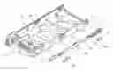
BRIEF DESCRIPTION OF THE DRAWINGSFIG. 1 is a perspective view of the sliding track structure of the invention.
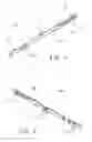
FIG. 2 is a side view of the sliding track structure of the invention.
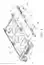
FIG. 3 is a schematic view of the sliding track structure of the invention in an assembly condition.
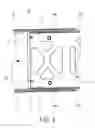
FIG. 4 is a schematic view of the sliding track structure of the invention for damping the shock in the vertical direction.
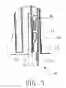
FIG. 5 is a schematic view of the sliding track structure of the invention for damping the shock in the horizontal direction.
DESCRIPTION OF THE PREFERRED EMBODIMENTThe sliding track structure of the invention is installed on one side of a server, to guide loading of the server into a rack and also provide a buffer and shock absorbing capability in the horizontal and vertical directions at the same time. The structure of the invention is simple and easy to install and remove, and can be produced at a low cost.
Referring to FIGS. 1, 2 and 3, the sliding track structure of the invention includes latch hooks 31, an upright elastic rib 32 and transverse elastic ribs 33. The latch hooks 31 are formed on the bottom side of a body 30 and pass through openings 11 formed on one side of a server 10 to latch on an inner side of the server 10. Therefore the body 30 is latched securely on one side of the server 10.
The body 30 has slots 34 to receive elastic side ribs 40. The elastic side ribs 40 are made of a deformable metal and are extended slightly from the slots 34 for a selected distance, and may be embedded in the slots 34 when subject to force. The elastic side ribs 40 can reduce the friction when the server 10 is loaded into the rack 20, so that loading and unloading of server 10 into or from the rack 20 is smoother.
The upright elastic rib 32 is formed on one end of the body 30 in a movable manner, and is extended from the top surface of the body 30 for a selected distance in normal condition. It can be pressed under force to be embedded in the body 30. The transverse elastic ribs 33 are formed in a middle portion of the body 30 and extended from two opposite sides of the body 30 for another selected distance, to receive a depression force and be housed in the body 30.
Refer to FIGS. 4 and 5 for the invention in use conditions. When the server 10 is loaded into the rack 20, the upright elastic rib 32 presses an inner top wall of a guiding track 21 of the rack 20 and is slightly embedded in the body 30. Similarly, the transverse elastic ribs 33 press an inner sidewall 23 of the guiding track 21 and are moved close to the body 30. Hence, with the upright elastic rib 32 and the transverse elastic ribs 33 pressing the rack 20, a buffer and shock absorbing capability in vertical and horizontal direction are provided.
After the invention is implemented, a buffer and shock absorbing capability in the vertical and horizontal direction are generated at the same time. The structure is simple, and installation and removal are easy. The production cost is low. Compared with the conventional techniques or the products now on the market that use springs, dampers, or linkage bars to reduce shocks, and that are costly to produce and difficult to install and remove and maintain, the invention provides a great improvement.
While the preferred embodiment of the invention has been set forth for the purpose of disclosure, modifications of the disclosed embodiment of the invention as well as other embodiments thereof may occur to those skilled in the art. Accordingly, the appended claims are intended to cover all embodiments, which do not depart from the spirit and scope of the invention.
Claims
WHAT IS CLAIMED IS:1. A sliding track structure to be installed on one side of a server to guide loading of the server into a rack, comprising a latch hook which mates the server and is extended into an inner side of the server to be latched thereon, a upright elastic rib extended from a top surface for a selected distance, and a transverse elastic rib extended from a lateral side for another selected distance; characterized in:
the upright elastic rib and the transverse elastic rib press respectively an inner top wall and an inner side wall of the rack when the server is loaded into the rack to provide a buffer and shock absorbing capability.
2. The sliding track structure of claim 1 further including an elastic side rib to reduce friction generated by the loading of the server into the-rack and unloading of the server from the rack.
3. The sliding track structure of claim 2 further having a slot to hold the elastic side rib.
4. The sliding track structure of claim 3, wherein the elastic side rib is extended slightly from the slot for a selected distance and is embedded in the slot when subject to a force.
5. The sliding track structure of claim 2, wherein the elastic side rib is made of a deformable metal.
6. The sliding track structure of claim 1, wherein the sliding track structure is made from plastics.
7. The sliding track structure of claim 1, wherein the sliding track structure is made of metal.
Images & Drawings included:
Sources:
- United States Patent and Trademark Office - verify current appl. status at the USPTO↗
Similar patent applications:
- » 20080250606
Sliding track assembly, hinge structure and sliding track assembly arrangement - » 20060163983
Structure slide track assembly - » 20080115329
Sliding track coupling structure for sliding doors - » 20070108880
Inner sliding rail mounting structure for sliding track assembly for drawer - » 20050225219
Coupling structure for a sliding track and a mounting bracket - » 20100201173
Sliding seat track having a secondary retaining structure - » 20220120100
Segmental track-changing and accumulative sliding construction method for unequal-span structure
Recent applications in this class:
- » 20250131946 2025-04-24
DEVICES AND METHODS FOR METAL ORGANIC FRAMEWORK (MOF) BASED OXYGEN REPLENISHMENT IN DATA STORAGE DEVICES - » 20190096442 2019-03-28
Elastic-plate fixing structure of tray for data accessing device - » 20170372757 2017-12-28
Computer system and computer casing - » 20100288898 2010-11-18
Mounting apparatus for data storage device - » 20100238618 2010-09-23
Electronic device with replaceable drive bracket - » 20100020484 2010-01-28
Fixing device - » 20090314609 2009-12-24
ITEM-CONVEYING DEVICE - » 20090182452 2009-07-16
Method of expanding a storage media library having interconnected doors and a replaced panel - » 20090168243 2009-07-02
Hard disk case - » 20090059510 2009-03-05
Drive conversion enclosure