METHOD FOR MANUFACTURING AN OPTICAL STORAGE MEDIUM
US20060278334A1
2006-12-14
11/423,164
2006-06-09
Abstract:
In a method for manufacturing an optical storage medium a first 1 and a second circular substrate 2 are being provided and being joined by means of a W curable resin forming an intermediate bonding layer. Then said two bonded substrates are being illuminated with UV light with the exception of the very outer edge of the bonded disc. Afterwards said two bonded disks are being spun and thereby a removal of unwanted resin (adhesive) from the outer edge takes place.
Assignee:
- Unaxis Balzers Ltd. 16 Balzers, Liechtenstein
Interested in similar patents?
Get notified when new applications in this technology area are published.
Classification:
G11B7/26 » CPC main
Recording or reproducing by optical means, e.g. recording using a thermal beam of optical radiation , reproducing using an optical beam at lower power ; Record carriers therefor; Record carriers characterised by shape, structure or physical properties, or by the selection of the material Apparatus or processes specially adapted for the manufacture of record carriers
B29C65/1406 » CPC further
Joining of preformed parts ; Apparatus therefor by heating, with or without pressure using wave energy or particle radiation characterised by the type of electromagnetic or particle radiation Ultraviolet [UV] radiation
B29C65/1496 » CPC further
Joining of preformed parts ; Apparatus therefor by heating, with or without pressure using wave energy or particle radiation making use of masks
B29C65/4845 » CPC further
Joining of preformed parts ; Apparatus therefor using adhesives, i.e. using supplementary joining material; solvent bonding characterised by the type of adhesives; Reactive adhesives, e.g. chemically curing adhesives Radiation curing adhesives, e.g. UV light curing adhesives
B29C65/521 » CPC further
Joining of preformed parts ; Apparatus therefor using adhesives, i.e. using supplementary joining material; solvent bonding applying the adhesive by spin coating
B29C66/1122 » CPC further
General aspects of processes or apparatus for joining preformed parts; General aspects dealing with the joint area or with the area to be joined; Particular design of joint configurations particular design of the joint cross-sections; Joint cross-sections comprising a single joint-segment, i.e. one of the parts to be joined comprising a single joint-segment in the joint cross-section; Single lapped joints Single lap to lap joints, i.e. overlap joints
B29C66/32 » CPC further
General aspects of processes or apparatus for joining preformed parts; General aspects dealing with the joint area or with the area to be joined Measures for keeping the burr form under control; Avoiding burr formation; Shaping the burr
B29C66/452 » CPC further
General aspects of processes or apparatus for joining preformed parts; General aspects of joining substantially flat articles, e.g. plates, sheets or web-like materials; Making flat seams in tubular or hollow articles; Joining single elements to substantially flat surfaces; Joining substantially flat articles ; Making flat seams in tubular or hollow articles; Joining of substantially the whole surface of the articles the article having a disc form, e.g. making CDs or DVDs
B29C66/723 » CPC further
General aspects of processes or apparatus for joining preformed parts characterised by the composition, physical properties or the structure of the material of the parts to be joined; Joining with non-plastics material characterised by the structure of the material of the parts to be joined being multi-layered
B32B37/1284 » CPC further
Methods or apparatus for laminating, e.g. by curing or by ultrasonic bonding characterised by using adhesives Application of adhesive
B29C66/712 » CPC further
General aspects of processes or apparatus for joining preformed parts characterised by the composition, physical properties or the structure of the material of the parts to be joined; Joining with non-plastics material characterised by the composition of the plastics material of the parts to be joined the composition of one of the parts to be joined being different from the composition of the other part
B29L2017/005 » CPC further
Carriers for sound or information; Carriers of records containing fine grooves or impressions, e.g. disc records for needle playback, cylinder records; Records or discs CD''s, DVD''s
B32B37/18 » CPC further
Methods or apparatus for laminating, e.g. by curing or by ultrasonic bonding characterised by the properties of the layers with all layers existing as coherent layers before laminating involving the assembly of discrete sheets or panels only
B32B2310/0831 » CPC further
Treatment by energy or chemical effects by wave energy or particle radiation using electromagnetic radiation using UV radiation
B32B2429/02 » CPC further
Carriers for sound or information Records or discs
B29K2069/00 » CPC further
Use of PC, i.e. polycarbonates or derivatives thereof , as moulding material
B29C66/71 » CPC further
General aspects of processes or apparatus for joining preformed parts characterised by the composition, physical properties or the structure of the material of the parts to be joined; Joining with non-plastics material characterised by the composition of the plastics material of the parts to be joined
B29K2033/12 » CPC further
Use of polymers of unsaturated acids or derivatives thereof as moulding material takes precedence; Polymers of esters Polymers of methacrylic acid esters, e.g. PMMA, i.e. polymethylmethacrylate
B32B37/00 IPC
Methods or apparatus for making layered products; Treatment of the layers or of the layered products
B32B37/00 IPC
Methods or apparatus for laminating, e.g. by curing or by ultrasonic bonding
B32B38/04 IPC
Ancillary operations in connection with laminating processes Punching, slitting or perforating
B32B37/26 IPC
Methods or apparatus for laminating, e.g. by curing or by ultrasonic bonding characterised by the properties of the layers with at least one layer which influences the bonding during the lamination process, e.g. release layers or pressure equalising layers
Description
This invention is useful in optical disc production, e.g. DVD-14/18, DVD+R Double Layer, Blu Disk Double Layer and other multi-layer media.
BACKGROUND OF THE INVENTIONThe common way to produce a dual layer single side DVD (like DVD-9) is to bond two 0.6 mm substrates together each carrying an information layer. But there are other ways to make a double layer disk. Instead of forming one layer in each substrate, those techniques use a single substrate structure with two internal information layers. This is not necessary for DVD-9 production but for other multilayer formats like DVD14/18 or DVD+R DL.
In the first step a first substrate with an information layer is produced by injection moulding and coated with layer material, which is appropriate for the format. Then a second substrate is produced with a second information layer—this second substrate is bonded together with the first substrate using typically a UV-curing adhesive. In the next step the 2 substrates are separated again, whereby the U resin with the image of the information layer of the second substrate must remain completely at the first substrate (transfer process) Depending on the application it is also possible to transfer a metallic layer in a similar way from the second to the first substrate.
For a good stamping or layer transfer result and an easy separation the material choice for the 2 substrates are important. The adhesion of the second substrate to the adhesive or the transfer layer has to be lower than the adhesion of all the other layers on the first substrate. Whereas polycarbonate is typically used for the first substrate, non-polar materials like PMMA are typically used for the second substrate. Alternatively the second substrate can be coated with an anti-adhesive coating for easy separation.
Due to the nature of the bonding process there will be a certain amount of resin at the outer edge of the 2 substrates. Whereas this extra amount of adhesive might be favourable for standard DVD production for a good sealing against the penetration of moisture it is a serious problem for the described processes for double/multilayer disk formation. Reason: After separation of the second substrate this adhesive material remains connected to the bonding layer and/or the first substrate. Due to its brittleness, the hardened adhesive forms a sharp rim around the first substrate and dust or particles can easily be created. Sticking on the surface of the media those particles are lowering the production yield significantly.
Furthermore, this sharp rim is causing process problems for the subsequent production steps. Cover layer formation for Blu disk, Dye coating using a spinning process (in the case of DVD+R DL) or final bonding to finish the DVD will be difficult unless measures are being taken to clean the outer edge.
RELATED ARTWO 03/98 607 describes a method to influence the thickness distribution in a layer of lacquer or adhesive on a single substrate. The fluid lacquer or adhesive is spin-distributed on a rotating substrate. By means of an adjustable diaphragm, different regions of the substrate are then exposed to U radiation. This way a kind of radially increasing hardening gradient is being achieved. An outer peripherical zone may be shielded in order to avoid exposure of the liquid lacquer to radiation.
However, with the invention at hand two bonded substrates are being used, which means, that the lacquer has to be cured by exposing it through the top (or bottom) substrate. The substrates however tend to deflect, reflect or absorb at least partially the UV-radiation.
SOLUTION ACCORDING TO THE INVENTIONTo solve the problem of adhesive around the outer edge according to this invention, the adhesive is removed from the outer edge in the low viscosity state before final curing with the following procedure. After joining of the two substrates the disk is illuminated with UV light, whereby measures are taken that the very outer edge of disk is shadowed from the UV light to prevent a hardening of the resin in this area. A viscosity difference of the bonding layer results due to this selective illumination: a high viscosity (hardened) state in the inner area and the information area and a lower viscosity state at the outer edge of the bonded disk.
In the next step, the disk will be rotated with a certain rotation speed. The lacquer in the high viscosity state will remain mostly unchanged, whereas the lacquer in the low viscosity state is mobile enough to be removed from the outer edge of the disk. In this spinning step the unwanted adhesive at the outer edge will be removed without changing the thickness distribution of the bonding layer in the information area of the disk.
Optionally, in a last process step the final curing of the disk has to be done if necessary.
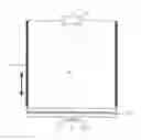
FIG. 1 shows a schematic overview over two bonded discs
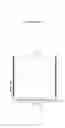
FIG. 2 shows a mask for the U curing of two bonded substrates according to an embodiment of the invention.
FIG. 1 illustrates a method for manufacturing an optical storage medium. After having provided a first 1 and a second circular substrate 2, said substrates 1, 2 are being joined by means of a UV curable resin forming an intermediate bonding layer 3. Then said two bonded substrates are being illuminated with UV light with the exception of the very outer edge of the bonded disc. Afterwards said two bonded disks are being spun and thereby a removal of unwanted resin (adhesive) 4 from the outer edge takes place.
With reference to FIG. 2, according to a special embodiment of the invention the 2 bonded substrates (lacquered disc) 10 are placed on a rotating table (not shown) underneath a UV lamp 13. A movable mask 11 is brought close to the surface of the disk. The mask 11 is shadowing the outer area of the disk 10 when the UV light 12 is switched on. It is possible to rotate the disk during illumination with a low rotation speed.
After the curing step the disk has to be accelerated to higher rotation speed to spin-off the outer edge lacquer. Spinning speed and time have to be carefully selected to prevent a change in the bonding layer in the information area of the disk.
Typical process parameters for the edge cleaning of 120 mm substrates are:
| Curing intensity: | 50 | mW/cm2 | |
| Curing time: | 1 | s | |
| Final spin speed: | 2000 | rpm | |
| Mask diameter: | 118 | mm | |
| Distance mask-disk: | 0.5 | mm | |
| Initial viscosity of the bonding lacquer: | 580 | mPas | |
In comparison with other techniques where the outer edge of the disks is cleaned after the final curing step, the removal of the adhesive from the outer edge in the uncured low viscose state avoids the risk of creating dust particles during cleaning. Those dust particles can be a potential reason for a low production yield.
Claims
What is claimed is:1. A method for manufacturing an optical storage medium comprising the following steps:
(a) providing a first (1) and a second (2) circular substrate
(b) joining said substrates by means of a UV curable resin forming an intermediate bonding layer (3)
(c) illuminating said two bonded substrates with UV light (12) with the exception of the very outer edge of the bonded disc
(d) spinning said two bonded disks and thereby removing unwanted resin (4) from the outer edge.
2. A method according to claim 1, further comprising
(e) curing the two bonded disks finally with UV light
3. A method according to claim 1, wherat the two bonded discs are being rotated during illumination in step (c)
4. A method according to claim 1, whereat a movable mask (11) is brought close to the surface of the two bonded disks (10) prior to illumination in step (c).
5. A method according to claim 4, whereat the mask (11) shadowing about 1 mm of the outer area of the disk during UV illumination in step (c).
6. A method according to claim 1, wherein the first (1) and second (2) substrates each carry an information layer.
7. A method according to claim 1, wherein the first substrate (1) is made from polycarbonate and the second substrate (2) is made from PMMA.
8. A method according to claim 1, wherein the first (1) and second (2) substrate are made from the same material and the second substrate (2) is covered with an anti-adhesive coating for later easy separation.
Images & Drawings included:
Sources:
- United States Patent and Trademark Office - verify current appl. status at the USPTO↗
Similar patent applications:
- » 20070206449
Optical storage medium, manufacturing method for optical storage medium, and optical storage device - » 20070166505
Optical storage medium, manufacturing method of recording layer thereof, and recording method thereof - » 20100195476
Optical storage medium comprising tracks with positive and negative marks, and stampers and production methods for manufacturing of the optical storage medium - » 20060059501
Method of manufacturing an optical data storage medium, optical data storage medium and apparatus for performing said method - » 20110097532
METHOD OF MANUFACTURING AN OPTICAL DATA STORAGE MEDIUM, OPTICAL DATA STORAGE MEDIUM AND APPARATUS FOR PERFORMING SAID METHOD - » 20080056111
Optical Data Storage Medium and Manufacturing Methods Therefor - » 20050005284
Optical storage medium and method of manufacturing same - » 20060164961
Method of manufacturing an optical storage medium and optical storage medium - » 20050213485
Optical information storage medium and method for manufacturing the same - » 20130202215
Surface shape measurement method, surface shape measurement apparatus, non-transitory computer-readable storage medium, optical element, and method of manufacturing optical element
Recent applications in this class:
- » 20190371360 2019-12-05
INFORMATION RECORDING MEDIUM, METHOD FOR PRODUCING SAME, AND SPUTTERING TARGET - » 20180122418 2018-05-03
ULTRASONIC MOLDING OF THIN WALL OPTICAL COMPONENTS - » 20170110147 2017-04-20
Holographic storage layer, holographic disk using the same, and method for manufacturing the same - » 20140193601 2014-07-10
Method for manufacturing multilayer structure sheet, and optical information recording medium - » 20140030531 2014-01-30
Minute structure and information recording medium - » 20130216730 2013-08-22
APPARATUS AND METHOD FOR MANUFACTURING OPTICAL RECORDING MEDIUM - » 20130196115 2013-08-01
Film for producing a sheet for a multilayer optical recording medium - » 20130034663 2013-02-07
Methods and systems relating to light sources for use in industrial processes - » 20120196077 2012-08-02
OPTICAL RECORDING MEDIUM AND PRODUCTION METHOD FOR OPTICAL RECORDING MEDIUM - » 20120181445 2012-07-19
ELECTRON BEAM RECORDING APPARATUS
Recent applications for this Assignee:
- » 20080083496 2008-04-10
Method for the dimensionally controlled bonding of surfaces - » 20070030563 2007-02-08
MULTI-BANDPASS FILTER FOR PROJECTION ARRANGEMENTS - » 20060245341 2006-11-02
REUSABLE STAMPER FOR OPTICAL DISK - » 20060238909 2006-10-26
Color wheel with aligned segments - » 20060225777 2006-10-12
Solar cell module and method of encapsulating same - » 20060197923 2006-09-07
System for projecting an image using narrow band light sources - » 20060175190 2006-08-10
Vacuum arc source comprising a device for generating a magnetic field - » 20060003476 2006-01-05
Method for the production of multilayer discs - » 20050241679 2005-11-03
Stripping apparatus and method for removal of coatings on metal surfaces - » 20050208211 2005-09-22
Component comprising submicron hollow spaces