Rotatable storage rack
US20060278593A1
2006-12-14
11/452,206
2006-06-14
Abstract:
A storage rack for storing an object rack includes a mounting component for mounting the storage rack to a mounting surface and a receiving component for receiving the object. The receiving component is rotatably attached to the mounting component. The receiving component includes a receiving component base plate defining a base plate central section, a base plate peripheral edge and a base plate intermediate section extending between the base plate central section and the base plate peripheral edge. A plurality of retaining walls extends from the base plate. The retaining walls are disposed circumferentially and oriented so as to extend in a radial direction leading from the base plate central section to the base plate peripheral edge. Each pair of adjacent retaining walls defines a corresponding wall spacing. The retaining walls diverge away from each other in the radial direction so that the size of the wall spacings increases in the radial direction. The object is adapted to be inserted in one of the wall spacings.
Interested in similar patents?
Get notified when new applications in this technology area are published.
Classification:
A47F5/02 » CPC main
Show stands, hangers, or shelves characterised by their constructional features Rotary display stands
A47B49/00 » CPC further
Revolving cabinets or racks; Cabinets or racks with revolving parts
A47F5/03 IPC
Show stands, hangers, or shelves characterised by their constructional features; Rotary display stands with horizontal rotation axis
Description
FIELD OF THE INVENTIONThe present invention relates to the general field of storage accessories and is particularly concerned with a rotatable storage rack for storing relatively flat articles such as container lids or the like.
BACKGROUND OF THE INVENTIONMost kitchens, whether of the household or of the professional type, are typically provided with various types of containers having corresponding lids. For example, most household kitchens are equipped with containers for temporarily storing food such as containers of the type made out of a substantially transparent polymeric resin and defining a peripheral rim. Such containers are provided with a substantially flat lid for closing the opening formed by the container. The lid is, in turn, provided with a lid rim having a peripheral recess adapted to fittingly and sealingly receive the container rim.
Most kitchens are also provided with various types of cookware including various types of pots and pans typically each provided with a corresponding lid. How and where the cookware and container lids are stored may vary substantially from kitchen to kitchen.
In some instances, the covers and lids are stored in a nested stack. However, most kitchens using this type of storage method are left with disorganized piles of lids and covers. An intended user wishing to access a specific lid or cover must hum or rummage through the pile in order to locate the correct lid for a given container. This exercise can prove to be both tedious and time-consuming.
In some kitchens, the pots, pans or containers are stored with their corresponding lids in a side by side relationship. In other words, each pot or pan has its corresponding lid resting contiguously. Although this method allows for quick and easy location of the appropriate lid, it nevertheless requires a significant amount of storage space. Accordingly, there exists a need for an improved storage rack.
SUMMARY OF THE INVENTIONIt is a general object of the present invention to provide an improved storage rack. In accordance with an embodiment of the present invention, there is provided a storage rack for storing an object, the storage rack being mountable to a mounting surface, the storage rack comprising: a mounting component for mounting the storage rack to the mounting surface; a receiving component for receiving the object; the receiving component being rotatably attached to the mounting component for rotation relative thereto; the receiving component including a receiving component base plate, the receiving component base plate defining a base plate central section, a base plate peripheral edge and a base plate intermediate section extending between the base plate central section and the base plate peripheral edge; the receiving component base plate also defining a base plate first surface and an opposed base plate second surface; a plurality of retaining walls extending from the base plate first surface, the retaining walls being disposed substantially circumferentially and oriented so as to extend in a substantially radial direction, such radial direction leading substantially from the base plate central section to the base plate peripheral edge; each pair of adjacent retaining walls defining a corresponding wall spacing therebetween, the retaining walls diverging away from each other in the radial direction so that the size of the wall spacings increases in the radial direction; whereby the object is adapted to be inserted in one of the wall spacings.
Conveniently, the retaining walls extend substantially perpendicularly from the base plate first surface. Conveniently, the plate peripheral edge has a substantially annular configuration.
Typically, each of the retaining walls defines a pair of opposed wall surfaces, at least a portion of at least one of the wall surfaces being provided with a friction enhancer for increasing the frictional force created between the at least one of the wall surfaces and the object when the object contacts the friction enhancer.
Conveniently, the friction enhancer includes a friction enhancing texture formed on the at least one of the wall surfaces.
Typically, each of the retaining walls defines a longitudinally extending wall anchoring edge anchored to the receiving component base plate and an opposed longitudinally extending wall free edge, at least one of the retaining walls being made of a resiliently deformable material allowing the at least one of the retaining walls to resiliently bend substantially laterally away from an adjacent retaining wall in a bent configuration, wherein, when in the bent configuration, the at least a portion of the wall free and anchored edges are in a substantially offset relationship relative to each other.
Conveniently, the retaining walls extend integrally from the receiving component base plate. Typically, the retaining walls are releasably attached to the receiving component base plate.
Conveniently, the receiving component base plate has a substantially disc-shaped configuration and the receiving component base plate is rotatably mounted to the mounting component for rotation about a rotational axis located substantially centrally relative to the receiving component base plate.
Typically, the base plate central section has a substantially disc-shaped configuration and the base plate intermediate section has a substantially annular configuration; the receiving component base plate being configured and sized such that the plate peripheral edge is spaced relative to the mounting surface by a greater distance than the base plate central section when the storage rack is mounted on the mounting surface. Conveniently, the base plate intermediate section is angled relative to the base plate central section by an intermediate-to-central section angle.
Typically, the mounting component includes a mounting component base plate for contacting the supporting surface; a mounting pin extending from the mounting component base plate; the receiving component base plate being provided with a pin receiving aperture for receiving the mounting pin; wherein when the mounting pin is inserted in the pin receiving aperture, the receiving component base plate is rotatable about the mounting pin relative to the mounting component base plate.
Conveniently, the mounting component base plate is provided with a fixing means for fixing the mounting component base plate to the supporting structure. Typically, the fixing means includes a fixing aperture extending through the mounting component base plate.
Conveniently, the storage rack further includes a spacing protrusion extending between the mounting component base plate and the mounting pin, the spacing protrusion having a contacting surface for contacting the base plate second surface and maintaining the receiving component base plate in a spaced relationship relative to the mounting component base plate.
Typically, the contacting surface is substantially smaller than the mounting component base plate. Conveniently, the contacting surface is provided with a friction reducing means for reducing the frictional force between the contacting surface and the receiving component second surface.
Advantages of the present invention include that the proposed storage rack allows for the storage of various types of objects including substantially flat objects such as the lids or covers of containers, pots, pans or the like. The proposed storage rack allows an intended user to quickly and easily store a given object in the rack and retrieve the object from the rack through a set of quick and ergonomic steps, without requiring manual dexterity.
The proposed storage rack allows and intended user to quickly locate a given object without the need for rumbling through other objects supported by the rack.
The proposed storage rack is designed so as to store the objects in a compact manner in order to reduce the required storage space.
The proposed storage rack is designed so as to be manufacturable using conventional forms of manufacturing in order to provide a storage rack that will be economically feasible, long-lasting and relatively trouble-free in operation.
BRIEF DESCRIPTION OF THE DRAWINGSAn embodiment of the present invention will now be disclosed, by way of example, in reference to the following drawings in which:
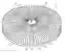
FIG. 1, in a perspective view, illustrates part of a rotatable storage rack in accordance with an embodiment of the present invention;
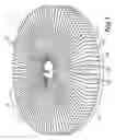
FIG. 2, in a partial cross-sectional view, illustrates some of the features of the rotatable storage rack shown in FIG. 1;
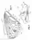
FIG. 3, in a partial top view with sections taken out, illustrates some of the features of the rotatable storage rack shown in FIGS. 1 and 2, the storage rack being shown storing a pair of items, the items being shown in phantom lines;
FIG. 4, in a partial perspective view with sections taken out, illustrates some of the features of the rotatable storage rack shown in FIGS. 1 through 3, the storage rack being used for storing three items, the three items being shown in phantom lines;
FIG. 5, in a perspective view, illustrates a mounting component part of a rotatable storage rack in accordance with an embodiment of the present invention.
DETAILED DESCRIPTIONReferring to FIG. 1, there is shown a rotatable storage rack in accordance with an embodiment of the present invention, the rotatable storage rack, hereinafter referred to as a storage rack, being referred to, generally, by the reference numeral 10. The storage rack 10 is adapted to be used for storing various types of objects and allowing easy retrieval of such objects. In FIGS. 3 and 4, the storage rack 10 is shown being used for storing relatively flat objects such as conventional container lids 12 of various shapes and sizes.
Although the storage rack 10 is particularly well suited for storing relatively flat objects such as the lids of conventional kitchen containers and cookware, compact discs, digital video discs, small books or the like it should be understood that the storage rack 10 could be used for storing other types of objects without departing from the scope of the present invention.
The storage rack 10 is adapted to be mounted to a suitable mounting surface such as a table top, a counter top or the like. Although the storage rack 10 is adapted to be mounted preferably to a substantially horizontal supporting surface, it should be understood that the storage rack 10 could be mounted on a substantially angled or even vertical surface without departing from the scope of the present invention.
As illustrated more specifically in FIGS. 2 and 3, in general terms, the storage rack 10 includes two main components, namely a mounting component generally indicated by the reference numeral 14 and a receiving component generally indicated by the reference numeral 16. The mounting component 14 is provided for mounting the storage rack 10 to a mounting surface (not shown) while the receiving component 16 is provided for receiving at least one and, typically, a plurality of objects such as the container lids 12 shown in FIGS. 3 and 4.
As indicated by arrow 18 in FIG. 1, the receiving component 16 is rotatably attached to the mounting component 14 for rotation relative thereto. The receiving component 16 includes a receiving component base plate 20.
As illustrated more specifically in FIG. 2, the receiving component base plate 20 typically defines a base plate central section 22, a base plate peripheral edge 24 and a base plate intermediate section 26 extending between the base plate central section 22 and the base plate peripheral edge 24. The receiving component base plate 20 also defines a base plate first surface 28 and an opposed base plate second surface 30.
As illustrated more specifically in FIG. 3, the receiving component 16 also includes a plurality of retaining walls 32 extending from the base plate first surface 28. The retaining walls 32 are disposed substantially circumferentially and are oriented so as to extend in a substantially radial direction. This radial direction leads substantially from the base plate central section 22 to the base plate peripheral edge 24.
Each pair of adjacent retaining walls 32 defines a corresponding wall spacing 34 therebetween. The retaining walls 32 diverge away from each other in the radial direction so that the size of the wall spacings 34 increases in the radial direction. The wall spacings 34 are adapted to frictionally accommodate the objects 12 therein.
As illustrated more specifically in FIG. 4, the retaining walls 32 typically extend substantially perpendicularly from the base plate first surface 28. Alternatively, at least one of the retaining walls 32 could extend at an angle from the base plate first surface 28 without departing from the scope of the present invention.
Typically, the plate peripheral edge 24 is circular in configuration. Alternatively, the plate peripheral edge 24 could have a substantially polyhedral or otherwise-shaped configuration without departing from the scope of the present invention.
Each retaining wall 32 defines a pair of opposed wall surfaces 36. Optionally, at least a portion of at least one of the wall surfaces 36 of at least one of the retaining walls 32 could be provided with a friction enhancing means or enhancer for increasing the frictional force created between that surface and an object when the latter contacts the friction enhancer. The friction enhancer could take any suitable form such as that of a friction enhancing texture formed on the wall surface 36.
As illustrated more specifically in FIGS. 2 and 4, each retaining wall 32 defines a corresponding longitudinally extending wall anchoring edge 38 anchored to the receiving component base plate 20. Each retaining wall 32 also defines a corresponding longitudinally extending wall free edge 40 located transversely opposite the corresponding wall anchoring edge 38.
As illustrated more specifically in FIG. 4, at least one of the retaining walls 32 and typically all of the retaining walls 32 are made of a resiliently deformable material allowing the latter to resiliently bend substantially laterally towards an adjacent retaining wall 32 or away from an adjacent retaining wall 32, in a bent configuration.
The reference numeral 42 is used, in FIG. 4, to illustrate schematically a bent portion of a retaining wall 32. The phantom lines show the retaining wall 32 bent simultaneously in both lateral directions in order to illustrate that a retaining wall 32 could potentially bend in both directions. When in a bent configuration, the portion of the wall free edge 40 is in an offset relationship relative to a corresponding wall anchored edge 38.
As illustrated more specifically in FIG. 2, the retaining walls 32 typically extend integrally from the receiving component base plate 20. Alternatively, at least one of the retaining walls 32 could be either permanently or releasably attached to the receiving component base plate 20. Typically, although by no means exclusively, the retaining walls 32 and the receiving component base plate 20 could be made out of an integral piece of polymeric resin.
At least one of the retaining walls 32 could optionally be coloured or otherwise visually identifiable so as to create visually distinct sections of the receiving component 16. For example, the receiving component 16 could be provided with an indicia marked on a retaining wall 32 or with an identifying tag (not shown) protruding outwardly from a retaining wall 32.
As illustrated more specifically in FIGS. 1 through 3, the receiving component base plate 20 typically has a substantially disc-shaped configuration and the retaining walls 32 typically form a radial array or walls. The receiving component base plate 20 is rotatably mounted to the mounting component 14 for rotation about a rotational axis 44 located substantially centrally relative to the receiving component base plate 20.
Typically, the base plate central section 22 has a substantially disc-shaped configuration and the base plate intermediate section 26 has a substantially annular configuration. The receiving component base plate 20 is typically configured and sized such that the base plate peripheral edge 24 is spaced relative to the mounting surface by a greater distance than the base plate central section 22 when the storage rack 10 is mounted on the mounting surface.
Typically, the base plate intermediate section 26 is angled relative to the base plate central section 22 by an intermediate-to-central section angle 46. As illustrated more specifically in FIG. 2, the intermediate-to-central section angle 46 typically has a value of a few degrees. It should, however, be understood that the intermediate-to-central section angle 46 could have other values without departing from the scope of the present invention.
FIG. 5 illustrates in greater details some of the features of the mounting component 14. The mounting component 14 typically includes a mounting component base plate 48. The mounting component base plate 48 is shown having a substantially disc-shaped configuration. It should, however, be understood that the mounting component base plate 48 could have other configurations without departing from the scope of the present invention.
The mounting component 14 also includes a mounting pin 50 extending from the mounting component base plate 48. As illustrated more specifically in FIGS. 2 and 3, the receiving component of base plate 20 is provided with a pin receiving aperture 52 for receiving the mounting pin 50. The pin receiving aperture 52 and the mounting pin 50 are configured and sized such that when the mounting pin 50 is inserted in the pin receiving aperture 52, the receiving component base plate 20 is rotatable about the mounting pin 50 relative to the mounting component base plate 48.
The mounting component base plate 48 is typically provided with a fixing means for fixing the mounting component base plate 48 to the supporting structure. The fixing means may take any suitable form including that of an adhesive, cooperating strips of miniature hook and loop fibre, double-sided tape, or any other suitable means.
In the embodiment shown in FIG. 5, the fixing means includes a set of fixing apertures 54 extending through the mounting component base plate 48. The fixing apertures 54 are adapted to receive fixing component such as screws, rivets or the like for permanently or reversibly fixing the mounting component base plate 48 to the supporting structure.
As illustrated more specifically in FIGS. 2 and 5, the mounting component 14 typically further includes a spacing protrusion 56 extending between the mounting component base plate 48 and the mounting pin 50. The spacing protrusion 56 has a contacting surface 58 for contacting the base plate second surface 30 and maintaining the receiving component base plate 20 in a spaced relationship relative to the mounting component base plate 48. Typically, the contacting surface 58 is substantially smaller than the mounting component base plate 48. Optionally, the contacting surface 58 may be provided with a friction reducing means for reducing the frictional force between the contacting surface 58 and the receiving component second surface 30.
In use, the mounting component 14 is initially secured using the fixing means to a suitable supporting surface such as the shelf of a kitchen storage cabinet, a counter top or the like. The receiving component 16 is then rotatably mounted on the mounting component 14 by inserting the mounting pin 50 in the pin receiving aperture 52 until the receiving component second surface 30 contacts the contacting surface 58.
The rotatable storage rack 10 may then be employed for releasably storing articles such as lids for containers, pots, pans or any other suitable object 12. Typically, the objects 12 are slidably inserted in a wall spacing 34 by sliding the object 12 radially inwardly in a direction leading from the base plate peripheral edge 24 toward the base plate central section 22.
Since the retaining walls 32 converge radially inwardly towards each other, the size of the wall spacing 34 between adjacent retaining walls 32 decreases in the radially inward direction. The object being slid radially inwardly between adjacent retaining walls 32 eventually reaches a radial position wherein at least a portion thereof frictionally contacts at opposed surfaces of adjacent retaining walls 32. Hence, the object 12 is frictionally retained between adjacent retaining walls 32.
Furthermore, since a portion of the retaining walls 32 located adjacent their respective free edge 40 is adapted to bend laterally, by continuing to slide the object radially inwardly, the deformable portion of the retaining walls 32 contacting the object will eventually have a tendency to deform laterally as indicated by the deflection generally indicated by the reference numeral 60 in FIG. 3. This deflection in a portion of the lateral walls 32 has the potential to further increase the retaining action of the retaining walls 32 on the object squeezed between adjacent retaining walls 32.
Furthermore, the potential for a lateral deflection of the retaining walls 32 allows adjacent retaining walls 32 to accommodate objects 12 having various configurations in the wall spacing 34 therebetween. For example, objects having a substantially non-flat configuration can be more easily accommodated in the wall spacing 34 by the lateral deflection of adjacent retaining walls 32.
Removal of the object 12 from the rotatable storage rack 10 may be performed either by pulling the object 12 upwardly in a direction leading away from the base plate first surface 28 or by sliding the object radially outwardly until the opposed surfaces of the retaining walls 32 no longer contact the object.
Since the receiving component 16 is rotatable relative to the mounting component 14, the receiving component 16 may be rotated in a desired angular relationship relative to the mounting component 14 in order to facilitate ergonomical access to selected regions of the receiving component 16. This may prove to be useful in a variety of situations.
For example, the rotatable storage rack 10 may be mounted on a shelf of a storage cabinet which only allows access to its interior content from a single direction. By rotating the receiving component, the storage capacity of the storage cabinet may be optimized without compromising on the ease with which objects may be either inserted into or removed from the rotatable storage rack.
Claims
The embodiments of the invention, in which an exclusive privilege or property is claimed, are defined as follows:1. A storage rack for storing an object, said storage rack being mountable to a mounting surface, said storage rack comprising:
a mounting component for mounting said storage rack to said mounting surface;
a receiving component for receiving said object;
said receiving component being rotatably attached to said mounting component for rotation relative thereto;
said receiving component including
a receiving component base plate, said receiving component base plate defining a base plate central section, a base plate peripheral edge and a base plate intermediate section extending between said base plate central section and said base plate peripheral edge; said receiving component base plate also defining a base plate first surface and an opposed base plate second surface;
a plurality of retaining walls extending from said base plate first surface, said retaining walls being disposed substantially circumferentially and oriented so as to extend in a substantially radial direction, such radial direction leading substantially from said base plate central section to said base plate peripheral edge; each pair of adjacent retaining walls defining a corresponding wall spacing therebetween, said retaining walls diverging away from each other in said radial direction so that the size of said wall spacings increases in said radial direction;
whereby said object is adapted to be inserted in one of said wall spacings.
2. A storage rack as recited in claim 1, wherein said retaining walls extend substantially perpendicularly from said base plate first surface.
3. A storage rack as recited in claim 1, wherein said plate peripheral edge has a substantially annular configuration.
4. A storage rack as recited in claim 1, wherein each of said retaining walls defines a pair of opposed wall surfaces, at least a portion of at least one of said wall surfaces being provided with a friction enhancer for increasing the frictional force created between said at least one of said wall surfaces and said object when said object contacts said friction enhancer.
5. A storage rack as recited in claim 4, wherein said friction enhancer includes a friction enhancing texture formed on said at least one of said wall surfaces.
6. A storage rack as recited in claim 1, wherein each of said retaining walls defines a longitudinally extending wall anchoring edge anchored to said receiving component base plate and an opposed longitudinally extending wall free edge, at least one of said retaining walls being made of a resiliently deformable material allowing said at least one of said retaining walls to resiliently bend substantially laterally away from an adjacent retaining wall in a bent configuration, wherein, when in said bent configuration, said at least a portion of said wall free and anchored edges are in a substantially offset relationship relative to each other.
7. A storage rack as recited in claim 1, wherein said retaining walls extend integrally from said receiving component base plate.
8. A storage rack as recited in claim 1, wherein said retaining walls are releasably attached to said receiving component base plate.
9. A storage rack as recited in claim 1, wherein said receiving component base plate has a substantially disc-shaped configuration and said receiving component base plate is rotatably mounted to said mounting component for rotation about a rotational axis located substantially centrally relative to said receiving component base plate.
10. A storage rack as recited in claim 9, wherein said base plate central section has a substantially disc-shaped configuration and said base plate intermediate section has a substantially annular configuration; said receiving component base plate being configured and sized such that said plate peripheral edge is spaced relative to said mounting surface by a greater distance than said base plate central section when said storage rack is mounted on said mounting surface.
11. A storage rack as recited in claim 1, wherein said base plate intermediate section is angled relative to said base plate central section by an intermediate-to-central section angle.
12. A storage rack as recited in claim 1, wherein said mounting component includes
a mounting component base plate for contacting said supporting surface;
a mounting pin extending from said mounting component base plate;
said receiving component base plate being provided with a pin receiving aperture for receiving said mounting pin;
wherein when said mounting pin is inserted in said pin receiving aperture, said receiving component base plate is rotatable about said mounting pin relative to said mounting component base plate.
13. A storage rack as recited in claim 12, wherein said mounting component base plate is provided with a fixing means for fixing said mounting component base plate to said supporting structure.
14. A storage rack as recited in claim 13, wherein said fixing means includes a fixing aperture extending through said mounting component base plate.
15. A storage rack as recited in claim 12, wherein said storage rack further includes a spacing protrusion extending between said mounting component base plate and said mounting pin, said spacing protrusion having a contacting surface for contacting said base plate second surface and maintaining said receiving component base plate in a spaced relationship relative to said mounting component base plate.
16. A storage rack as recited in claim 15, wherein said contacting surface is substantially smaller than said mounting component base plate.
17. A storage rack as recited in claim 15, wherein said contacting surface is provided with a friction reducing means for reducing the frictional force between said contacting surface and said receiving component second surface.
Images & Drawings included:

Sources:
- United States Patent and Trademark Office - verify current appl. status at the USPTO↗
Similar patent applications:
- » 20200348075
Refrigerator, refrigerator door and rotatable storage rack - » 20180292051
Cryogenic storage rack including rotatable shelves, and associated storage systems and methods - » 20200120925
Method of storing and retrieving products using cryogenic storage rack with rotatable shelves - » 20250083753
VEHICLES INCLUDING TRUCK BED STORAGE SYSTEMS WITH ROTATING RACK ASSEMBLIES - » 20080285172
Method for transporting a tape cartridge within a tape library storage system utilizing a curved rack section and independently rotatable teeth
Recent applications in this class:
- » 20250017394 2025-01-16
Rotating Shelf Adjustment Collar - » 20240382018 2024-11-21
Ornament carousel holder - » 20210169238 2021-06-10
Rotating collectible display - » 20170295955 2017-10-19
Easy reach basket carousel - » 20160227943 2016-08-11
Rotating Pegboard Storage/Display Unit, Using Right Angle Joinery - » 20140084773 2014-03-27
Spray Bottle Rack - » 20130328467 2013-12-12
Rotatable multilevel tool organizer - » 20130037680 2013-02-14
DEVICE FOR THE ROTATION OF OBJECTS (EMBODIMENTS) SET FOR THE ROTATION OF OBJECTS - » 20110315645 2011-12-29
Display unit with interchangeable shelving - » 20110220599 2011-09-15
Tray for carrying food and contained beverages