Tool box having latching device
US20060278635A1
2006-12-14
11/439,099
2006-05-23
Abstract:
A tool box having a latching device is described. The tool box includes a first housing, a second housing and a latching device. The first housing has a first containing space and a first side surface enclosing the first containing space. The second housing has a second containing space and a second side surface enclosing the second containing space. Opposing edges of the first and second housings are rotatably connected to each other to pivot the first housing to the second housing about a pivot axis therebetween. The latching device is movably mounted on the first side surface and the second side surface to selectively lock the first and the second housings to form an aligned arrangement with the first housing co-planar with the second housing. A skid-proof member is attached to the side surfaces to induce a friction with a fixture surface for holding the tool box on the fixture surface in an open status.
Interested in similar patents?
Get notified when new applications in this technology area are published.
Classification:
B25H3/003 » CPC main
Storage means or arrangements for workshops facilitating access to, or handling of, work tools or instruments Holders for drill bits or the like
B25H3/025 » CPC further
Storage means or arrangements for workshops facilitating access to, or handling of, work tools or instruments; Boxes comprising a number of connected storage elements movable relative to one another for access to their interiors by rotation about a common axis
Description
FIELD OF THE INVENTIONThe present invention relates to a tool box for carrying tool accessories of different sizes and lengths, such as various types of drill bits and screwdrivers, and more particularly to a tool box having at least one latching device selectively and releasably retaining the tool box in a planar locked condition, the tool box being transformable from the locked condition to an erected usage condition by releasing the latching device.
BACKGROUND OF THE INVENTIONConventionally, tool accessories, such as drill bits and screwdrivers, are often carried in a box or otherwise packed for use and being displayed at a sale location in a retail store. U.S. Pat. No. 6,685,018 B1 issued on Feb. 3, 2004 discloses a display case, a carry case and a storage stand for elongated tools, such as screwdrivers. The screwdrivers are received in open slots, which cannot stably secure the screwdrivers, so that upon being shaken, the screwdrivers may easily get loosened and drop off the tool box. Furthermore, the tool box is composed of two movable housings, which when in an open status, are secured by a latching mechanism provided at connection between the housings. The latching mechanism provides a locking force to secure the housing in the open status and the locking force acts in a direction substantially the same as the moving direction of the housings in opening or closing the housing. Consequently, mechanical strength of the tool box in the open status is relatively weakened.
U.S. Pat. No. 5,957,285 issued on Sep. 28, 1999 also discloses a tool box. The tool box comprises two pivotally connected parts, which receive and retain tools, and a bottom part that accommodates the connected parts. Another prior art reference, U.S. Pat. No. 6,978,890 B2 issued on Dec. 27, 2005, discloses a screwdriver bit package. The tool boxes of both references contain many parts and complicated structure, making the use thereof inconveniently.
Consequently, there is a need to develop a tool box to solve the above-mentioned problems.
SUMMARY OF THE INVENTIONOne objective of the present invention is to provide a tool box featuring stably retaining tool accessories, improved mechanical strength, and simple structure.
Another objective of the present invention is to provide a tool box having latching means for allows pivoted portions of the box to selectively switch between a planar locked status and an open usage status for convenience of use.
According to the above objectives, the present invention sets forth a tool box. The tool box comprises a first housing, a second housing and latching devices. The first housing has a first containing space and a first side surface enclosing the first containing space. The second housing has a second containing space and a second side surface enclosing the second containing space. The first and second housings also have opposing jointing edges that are rotatably connected together to pivot the first housing to the second housing about a pivot axis therebetween.
Latching devices are arranged on the first side surface of the first housing and the second side surface of the second housing. The latching device is movable to lock the first and the second housings to form an aligned arrangement. Specifically, the first housing is co-planar with the second housing when the latching device locks the first housing and the second housing in the aligned arrangement.
In one embodiment, the first and the second containing spaces comprise a plurality of cavities for containing tool accessories and recessed regions alternating the cavities to partially receive the tool accessories. A skid-proof part is attached to the side surfaces of the first and the second housings to help maintaining the tool box in an open status on a fixture surface with a frictional force induced between the skid-proof part and the fixture surface.
The advantages of the present invention generally include: (a) a latching device of the tool box that locks the housings in an aligned arrangement to improve the structure strength and to simplify structure of the tool box; and (b) the side surfaces of the second housings having skid-proof parts for convenient use when the tool box is in the open status.
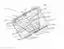
BRIEF DESCRIPTION OF THE DRAWINGSFIG. 1 is a perspective view of a tool box according to a first embodiment of the present invention in a planar locked/closed status.
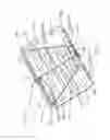
FIG. 2 is a perspective view of a tool box of the present invention in an open usage status.
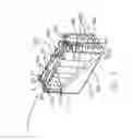
FIG. 3 is a perspective view of a tool box according to a second embodiment of the present invention in a cover-closed status.
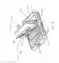
FIG. 4 is a perspective view of the tool box of the present invention in a cover-open status with covers of the tool box opened.
DETAILED DESCRIPTION OF THE PREFERRED EMBODIMENTSFor a better understanding of the preferred embodiments of the present invention, reference is to be made to the accompanying drawings.
With reference to the drawings and in particular to FIGS. 1 and 2, wherein FIG. 1 is a perspective view of a tool box, generally designated with reference numeral 10, according to first embodiment of the present invention in a locked/closed status, and FIG. 2 shows the tool box 10 in an open status, the tool box 10 comprises a first housing 1, a second housing 2 and a latching device 3. The first housing 1 is rotatably connected to the second housing 2 by a hinge having a pivot axis 6, whereby the housings (1, 2) are rotatable about the axis 6 with respect to each other between the locked/closed status and the open status. The hinge can be replaced by any device having equivalent function, such as a flexible belt-like portion extending between the housings (1, 2).
The first housing 1 has a first containing space 501 and a circumferential side surface 402 partially surrounding and delimiting the first containing space 501. The second housing 2 has a second containing space 502 and a circumferential side surface 403 partially surrounding and delimiting the second containing space 502. The first housing 1 has an jointing edge 404 (shown in FIG. 2) that is not enclosed by the side surface 402, which edge 404 is connected to a corresponding jointing edge 405 (shown in FIG. 2) of the second housing 2 that is not enclosed by the circumferential side surface 403 so as to pivot the first housing 1 to the second housing 2 with the pivot axis 6 extending between and along the connected edges (404, 405).
The first and the second containing spaces (501, 502) comprise a plurality of cavities (102, 202) for containing tool accessories (not shown), the cavities 102 and 202 alternating each other. The first containing space 501 comprises a plurality of recessed regions 101 each between adjacent cavities 102 and corresponding in position to the cavities 202 of the second containing spaces 502. Similarly, the second containing space 502 comprises a plurality of recessed regions 201 each between adjacent cavities 202 and corresponding to the cavities 102 of the first containing spaces 501.
Additionally, a latching slot 302 is defined in and partially co-extending with segments of the circumferential side surfaces (402, 403) of the first housing 1 and the second housing 2 that are aligned with each other when the tool box is in the locked status. In the embodiment illustrated, the tool box 10 in the locked status has a rectangular configuration and two latching slot 302 are defined respectively on opposite lateral sides of the box 10. However, it is apparent that there can be only one latching slot 302 defined along one lateral side of the tool box 10 that extends across both the first and second housings (1, 2). In the embodiment illustrated, the circumferential side surfaces (402, 403) of each housing (1, 2) of the rectangular tool box 10 is composed of segments of the lateral sides of the tool box 10 and a remote edge segment that connects between the lateral sides, the remote edge being opposite to the edge that joints between the first and second housings (1, 2).
The first housing or the second housing (1, 2) selectively forms, within the first containing space 501 or the second containing space 502, a label position 7 for label attachment.
Latching devices 3 are movably mounted on the lateral side segments of the circumferential side surfaces (402, 403) of both the first housing 1 and the second housing 2. In the embodiment illustrated, two latching devices 3 are arranged on opposite lateral sides of the tool box 10, but it is apparent one latching device 3 mounted on one lateral side is sufficient for the operation of the tool box 10. Each latching device 3 is selectively movable to a position to lock the first and the second housings (1, 2) to form an aligned housing arrangement, where the tool box 10 is in a planar form as shown in FIG. 1. Specifically, the first housing 1 is substantially co-planar with the second housing 2 when the latching devices 3 moves along the circumferential side surfaces (402, 403) of the first housing 1 and the second housing 2 to positions where the latching devices 3 straddle over the pivot axis 6.
Preferably, the latching device 3 comprises a fastening unit, such as a bolt, mounted on the latching device 3. The fastening unit is snugly and slidably received in the latching slot 302 so as to partially located in both the first and the second housing (1, 2) to maintain and secure the first and the second housings (1, 2) in the locked, aligned arrangement. Preferably, the fastening unit is mounted on an inside surface of the latching device 3 adjacent to circumferential side surfaces (402, 403) of the first and second housings (1, 2).
In another embodiment of the present invention, the latching device 3 is located in the internal sidewall of the first and the second housing (1, 2). The latching device 3 slides along the arrowhead direction 301 thereon to switch the first and second housings (1, 2) from the locked status to the unlocked/open status. When the latching device 3 is in the locked status, the upper surface 103 of the first housing 1 and the upper surface 203 of the second housing 203 are substantially aligned and co-planar with each other.
In one embodiment, the sizes of the cavities (102, 202) are different and the sizes of at least some of the recessed regions (101, 201) of the first and the second housings (1, 2) are made different. The sizes of the cavities (102, 202) and the recessed regions (101, 201) are decreased progressively from one side surface to opposite side surface within the first and the second housings (1, 2). With respect to positional arrangement, the cavities (102, 202) and the recessed regions (101, 201) of the first and the second housings (1, 2) are alternating and spaced from each other. Therefore, when the latching device 3 is positioned in the locked status, prolonged tools, such as drill bits or screwdrivers, can be arranged in the cavities (102, 202) of the first and the second containing spaces (501, 502) and partially received in the recessed regions (101, 201).
Referring to FIG. 1 again, when the latching device 3 is located in the locked status, a trapezoid concave region 5 composed of the first and the second containing space (501, 502) is formed and lower than the upper surfaces 103, 203 of the first and the second housings (1, 2). Thus, the cavities (102, 202) and the recessed regions (101, 201) are arranged in the concave trapezoid region 5.
A skid-proof part 4 is formed on and at least partly extending along each circumferential side surface (402, 403) of the first and the second housings (1, 2). The skid-proof part 4 is made of elastic or soft material of high frictional coefficient, such as rubbers or soft plastics. Since the material of the skid-proof part 4 is soft and of substantial friction and since at least a portion of the skid-proof part 4 is formed or mounted on the positioned corresponding to the remote end edge of each housing (1, 2), when the first and second housings (1, 2) of the tool box 10 is rotated about the pivot axis 6 to overlap each other as shown in FIG. 2 (or at a configuration that the housings (1, 2) are inclined with respect to each other) and the tool box 10 is positioned on a fixture surface with the portion of the skid-proof part 4 engaging the fixture surface, a friction force is induced between the side surface 402 (or more specifically, the skid-proof part 4) and the fixture surface so as to stably maintain the first and the second housings (1, 2) of the tool box 10 in the open status for positioning/retrieving tool accessories (not shown) into/from the tool box 10 while the first and second housings (1, 2) are unlocked and folded.
In one embodiment, a portion of skid-proof material or skid-proof stripes that constitute the skid-proof part 4 can be attached to the first and the second housings (1, 2) or in corresponding positions of the circumferential side surfaces (402, 403) of the first and the second housings (1, 2). In addition, the circumferential side surfaces (402, 403) of the first and the second housing (1, 2) comprise shallow recesses 401 for easy handling of the tool box 10.
In operation, the latching device 3 is moved along the arrowhead direction 301 from the locked status to the open, unlocked status. Then, the first and the second housings (1, 2) are rotated an arbitrary angle, such as 90 degrees, around the pivot axis 6 so that the first and the second housings (1, 2) overlap each other in a back-to-back manner. Afterwards, the tool box 10 in the open status is placed on a fixture surface so that a user can access desired tool accessories.
Referring now to FIG. 3 and 4, wherein FIG. 3 is a perspective view of a tool box according to a second embodiment of the present invention in a cover-closed status, and FIG. 4 is a perspective view of the tool box 10 in a cover-open status. Further, to fully utilize a back side region of the tool box 10 to for example receive and contain more tool accessories in the tool box 10, the back side of the tool box 10 is made recessed, substantially opposite to and corresponding in position to each of the first and second containing spaces (501, 502), and a cover 8 is connected to the pivot axis 6 to openably cover each back side recess of the tool box 10. The cover 8 is releasably buckled to the circumferential side surfaces (402, 403) of the first and the second housings (1, 2), especially the remote end edge, by a buckle device 9. The buckle device 9 comprises a hook (912, 922) formed on the cover 8 and a protrusion (911, 921) formed on the first or second housing (1, 2) to releasably engage the hook (912, 922). In another embodiment, the pivot axis 6 of the cover 8 can be located in other region of the first and the second housing (1, 2).
To summarize, the advantages of the present invention generally include: (a) a latching device of the tool box for selectively locking the first and the second housings in an aligned arrangement by sliding along the side surfaces of housings to improve the structure strength and to simplify the structure of the tool box; and (b) the side surfaces of the second housings having skid-proof parts for convenient use when the tool box is in the open status.
As is understood by a person skilled in the art, the foregoing preferred embodiments of the present invention are illustrative rather than limiting of the present invention. It is intended that they cover various modifications and similar arrangements be included within the spirit and scope of the appended claims, the scope of which should be accorded the broadest interpretation so as to encompass all such modifications and similar structure.
Claims
What is claimed is:1. A tool box, comprising:
a first housing having a first containing space and a first side surface comprising at least one segment enclosing the first containing space, and a first jointing edge;
a second housing having a second containing space and a second side surface comprising at least one segment enclosing the second containing space, and a second jointing edge opposing the first jointing edge, wherein the jointing edges are connected to each other in a rotatable manner to pivot the first housing to the second housing about a pivot axis therebetween; and
at least one latching device arranged on both the first side surface and the second side surface to be movable to a locked position, wherein the latching device locks the first and the second housings to form an aligned arrangement with the first housing co-planar with the second housing.
2. The tool box of claim 1, wherein the latching device comprises a fastening unit slidably received in a latching slot partially extending along the segments of the first side surface and the second side surface, and when the first side surface is aligned to the second side surface in the aligned arrangement of the first and second housings, the fastening unit slides along the latching slot to the locked position to lock the first and the second housings in the aligned arrangement.
3. The tool box of claim 2, wherein one of the first and the second containing spaces comprises a plurality of cavities for containing tool accessories.
4. The tool box of claim 3, wherein another of the first and the second containing spaces comprises a plurality of recessed regions corresponding in position to the cavities of said one of the first and the second containing spaces.
5. The tool box of claim 4, wherein the cavities are of different sizes and wherein the recessed regions are of different sizes.
6. The tool box of claim 5, wherein the sizes of the cavities and the recessed regions are decreased progressively from one side surface to an opposite side surface of the first and the second housings.
7. The tool box of claim 6, wherein the cavities and the recessed regions of the first and the second housings are alternated and spaced.
8. The tool box of claim 1, further comprising a skid-proof part attached to at least one of the first and second side surfaces.
9. The tool box of claim 1, wherein at least one of the first and second side surfaces forms notches for easy handling of the tool box.
10. The tool box of claim 1, wherein a back surface of the tool box opposite to at least one of the first and the second containing spaces forms a recessed space and a cover openably closing the recessed space.
Images & Drawings included:

Sources:
- United States Patent and Trademark Office - verify current appl. status at the USPTO↗
Recent applications in this class:
- » 20250135627 2025-05-01
TOOL HOLDER RAIL AND TOOL HOLDER INCLUDING THE SAME - » 20250083298 2025-03-13
TOOL ACCESSORY HOLDER, TOOL SYSTEM, AND TOOL ACCESSORY STORAGE SYSTEM - » 20250058455 2025-02-20
Packaging Device for an Accessory Device - » 20250058454 2025-02-20
Hand tool holder structure - » 20250033187 2025-01-30
SOCKET HOLDING FRAME - » 20240408740 2024-12-12
Socket Storage Device - » 20240316749 2024-09-26
ARRANGEMENT COMPRISING A RECEIVING DEVICE FOR REMOVABLE ATTACHMENT OF A SCREW BIT HOLDER AND A RECEIVING DEVICE - » 20240246219 2024-07-25
SMART ACCESSORY STORAGE DEVICE - » 20240217086 2024-07-04
Tool holder module - » 20240208038 2024-06-27
Hex wrench holder structure