Container
US20060278636A1
2006-12-14
11/146,878
2005-06-08
Abstract:
A container includes an outer container and an inner container. The outer container consists of an outer container half body, a cap above the outer container half body separated by an opening, a connect rod fixed at an outer surface of the outer container half body and extending up to have its upper end fixed with the cap. The inner container consists of a lower inner container body placed in the outer container half body, and an upper inner annular container body positioned on the lower inner container body and fitting in the opening of the outer container. Thus the material for the outer container is reduced, and the upper inner annular container body can be colored variously to increase the value of the container, and to cut down the product cost.
Interested in similar patents?
Get notified when new applications in this technology area are published.
Classification:
B65F1/08 » CPC main
Refuse receptacles; Accessories therefor with removable inserts with rigid inserts
B65F1/163 » CPC further
Refuse receptacles; Accessories therefor; Other constructional features; Accessories; Lids or covers with means for assisting the opening or closing thereof, e.g. springs Pedal-operated lids
B65F2250/11 » CPC further
Materials of refuse receptacles Metal
Description
BACKGROUND OF THE INVENTION1. Field of the Invention
This inventin relates to a container, particularly to one made of compound materials consisting of metal for an outer container body and non-metal for an inner container body so as to give variations to the containers and to cut down its cost.
2. Description of the Prior Art
Metal containers of a tank shape are widely used for many purposes, the most usual one is a garbage can, and stainless steel is the most common material sought after. But there is an outlook disadvantage that a welded straight line scar is usually found in a tank-shaped stainless garbage can, as a stainless plate is wound and then the two ends are welded together to leave a straight welded line on the outer surface. Moreover, this kind of garbage can is mostly high, so it is difficult to form it by extracting and very apt to give rise to disqualified products. In addition, the wound tank-shaped garbage can is very difficult to form a rolled edge on an upper opening.
SUMMARY OF THE INVENTIONThe feature of the invention is a metal outer container and a non-metal inner container combined together for making a container. The inner container consists of a lower inner container body and an upper inner annular container body, and the lower inner container body is placed in the outer container body, to let the upper inner annular container body exposed out on the outer container body so as to be colored variously to increase the beauty of the container and to reduce its cost.
BRIEF DESCRIPTION OF DRAWINGSThis invention will be better understood by referring to the accompanying drawings, wherein:
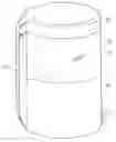
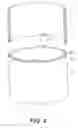
FIG. 1 is a perspective view of a first embodiment of a container in the present invention;
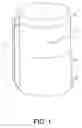
FIG. 2 is an exploded perspective view of the first embodiment of a container in the present invention;
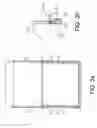
FIG. 3a is a cross-sectional view of the first embodiment of a container in the present invention;
FIG. 3b is a magnified view of the part A marked in FIG. 3a;
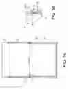
FIG. 4 is a partial cross-sectional view of a second embodiment of a container in the present invention;
FIG. 5a is a cross-sectional view of the second embodiment of a container in the present invention;
FIG. 5b is a magnified view of the part B marked in FIG. 5a;
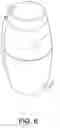
FIG. 6 is a perspective view of a container with a different shape from the ones illustrated above;
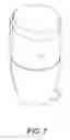
FIG. 7 is a perspective view of a container with another different shape from the ones illustrated above.
DETAILED DESCRIPTION OF THE PREFERRED EMBODIMENTSA first embodiment of a container in the present invention, as shown in FIGS. 1, 2 and 3, includes an outer metal container body 1 and an inner non-metal container body 1 as main components combined together.
The outer metal container body 1 is composed of a outer metal half container body 10 of a cylindrical shape, a connect rod 11 fixed vertically on an outer surface and extending upward, and a cap 12 fixed sidewise with an upper end of the connect rod 11 just above the outer metal half body 10. So there is an opening between the outer metal half container body 10. Further, a pedal 13 is provided at an outer lower surface of the outer metal half container body 10, connected with the connect rod 11 to interact with each other for opening the cap 12.
The inner non-metal container body 2 made of non-metal is composed of a lower inner container body 20 and an upper inner annular container body 21 to rest on the lower inner container body 20. The lower inner container body 20 is provided with a plurality of fitting lugs 200 spaced apart equidistantly on an upper flange 201, and the upper flange 201 rests on the upper opening of the outer metal half container body 10. The upper inner container body 21 has its lower annular edge provided with plural elastic lugs 210 with a groove spaced apart equidistantly so that the upper inner annular container body 20 may have its outer surface flush with the outer surface of the outer metal half container body 10 of the outer metal container body 1 after the upper inner container body 21 is superposed stably on the lower inner container body 20, with the fitting lugs 200 fitting in the grooves of the elastic lugs 210. And the upper inner annular container body 21 fits in the opening between the outer metal half container body 10 and the cap 12.
In using, firstly, the upper inner container body 21 is combined on the lower inner container body 20, with the elastic lugs 210 fitting with the fitting lugs 200. Next, the whole inner container body 2 is placed in the outer metal half body 10 of the outer metal container body 1, with the upper flange 201 resting on the upper opening of the outer metal half container body 10, and with the outer surface 211 flush with the outer surface of the outer metal half body 10. Then the container is finished in its assembly, ready for use. Then the pedal 13 is pressed to move up the connect rod 11, which is then to move up and open the cap 12 for waste paper possible to be thrown into the container.
Next, a second embodiment of a container in the invention is shown in FIGS. 4 and 5, includes an outer metal container 1 and an inner non-metal container body 3 as main components combined together.
The outer metal container body 1 has an outer metal half container body 10 of the half height of the whole container, and a connect rod 11 (not shown, but the same as that in the first embodiment) fixed at an outer surface of the outer metal half container body 10, and a cap 12 pivotally connected with an upper end of the connect rod 11 to move together with the connect rod 11.
The inner non-metal container body 3 made of non-metal is composed of a lower inner container body 30 and an upper inner annular container body 31 positioned on the lower inner container body 30. The lower inner container body 30 has plural fitting lugs 300 on an upper annular edge spaced apart equidistantly and a flange 301 under the upper annular edge to rest on the upper opening of the outer metal half container body 10, and the upper inner container body 31 has plural fitting notches 310 spaced apart equidistantly in a lower annular edge and its outer surface 311 flush with the outer surface of the outer metal half container body 10.
In using the second embodiment of the container, firstly the upper inner container body 31 is combined stably with the lower inner container body 30 by rotating properly to let the fitting notches 310 engaging with the fitting lugs 300. Then the whole inner container 3 is placed in the outer metal container body 1, with the flange 301 sitting stably on the opening of the outer container body 10, and with the outer surface 311 flush with the outer surface of the outer metal half container body 10. Then the second embodiment of the container is finished in assembly, and the pedal 13 is stepped down to move up the connect rod 11, which accordingly pushes up the cap 12 for waste paper possible to be thrown into the container.
The invention has the following as can be understood from the foresaid description.
-
- 1. The material cost of the outer metal half container body 10 can be cut down, to upgrade its competitive marketing force.
- 2. Using different materials of the inner container body can change the product value of a container with compound materials.
- 3. The structure of the inner container composed of a lower inner and an upper inner annular container body can effectively cut down the cost for their mold and accordingly the product cost, too.
- 4. The outer shape of the container can be changed as shown in FIGS. 6 and 7, making variously valued products.
While the preferred embodiments of a container have been described above, it will be recognized and understood that various modifications may be made therein and the appended claims are intended to cover all such modifications that may fall within the spirit and scope of the invention.
Claims
What is claimed is:1. A container comprising:
an outer container consisting of an outer container body, a cap, a connect rod and a pedal, an opening provided between said outer container body and said cap;
an inner container consisting of a lower inner container body and an upper inner annular container body, said inner container made of non-metal, said lower inner container body placed in said outer container body, said lower inner container body and said upper annular inner container body combined stably together by means of engaging of fitting lugs and elastic fitting lugs with a groove provided on said upper and said lower inner container body.
2. A container comprising:
an outer container consisting of an outer container body, a connect rod, a cap and a pedal, an opening provided between said outer container body and said cap;
an inner container consisting of a lower inner container body and an upper inner annular container body, said inner container made of non-metal, said lower inner container body placed in said outer container body, said lower inner container body and said upper annular inner container body combined together stably by means of engaging of fitting lugs and fitting notches provided on said lower inner container body and said upper inner annular container body.
3. The container claimed in claim 1 or 2, wherein said upper inner annular container body is just located in said opening of said outer container, and said upper inner annular container is colored variously for increasing the value of its outer appearance.
Images & Drawings included:
Sources:
- United States Patent and Trademark Office - verify current appl. status at the USPTO↗
Similar patent applications:
- » 20120231379
Fluorine-containing resin particle dispersion, method for preparing fluorine-containing resin particle dispersion, coating liquid which contains fluorine-containing resin particles, method for preparing coating film which contains fluorine-containing resin particles, coating film which contains fluorine-containing resin particles, molded body, electrophotographic photoreceptor, method for preparing electrophotographic photoreceptor, image forming apparatus, and process cartridge - » 20160291490
Fluorine-containing resin particle dispersion, method for preparing fluorine-containing resin particle dispersion, coating liquid which contains fluorine-containing resin particles, method for preparing coating film which contains fluorine-containing resin particles, coating film which contains fluorine-containing resin particles, molded body, electrophotographic photoreceptor, method for preparing electrophotographic photoreceptor, image forming apparatus, and process cartridge - » 20240208713
LIQUID-CONTAINING COMBINATION CONTAINER, CONTAINER SET, METHOD OF MANUFACTURING LIQUID-CONTAINING CONTAINER, AND USE OF LIQUID-CONTAINING COMBINATION CONTAINER - » 20250066081
LIQUID-CONTAINING CONTAINER, LIQUID-CONTAINING COMBINED CONTAINER, CONTAINER, STOPPER, AND METHOD FOR PRODUCING LIQUID-CONTAINING CONTAINER - » 20220388744
Cap of container, container and content containing body, method for producing cap of container and container cap producing apparatus, and method for producing content containing body and content containing body producing apparatus - » 20240327071
CROWN CAP FOR ATTACHMENT TO A MOUTH OPENING OF A CONTAINER COMPRISING FIBERS AND FOR CLOSING THE MOUTH OPENING BY MEANS OF THE CROWN CAP, CONTAINER WITH A CONTAINER BODY COMPRISING FIBERS AND WITH A CROWN CAP, CONTAINER BODY COMPRISING FIBERS, METHOD FOR ARRANGING THE CROWN CAP ON THE CONTAINER BODY COMPRISING FIBERS, AND DEVICE FOR ARRANGING THE CROWN CAP ON THE CONTAINER BODY COMPRISING FIBERS - » 20090171489
Interchangeable drive element for bottle or container supports in a container labeling machine or a machine configured to print information on bottles or containers, which interchangeable drive element is capable of being used in different container labeling or container information printing machines in bottle or container filling plants - » 20210206618
Container for storing a liquid, pressure valve therefor and use of the container as a beer barrel; method for controlling the pressure in a container of this type; hollow container base, modular system for producing a hollow container base and method for filling a container - » 20060104672
Powder container, powder contained product, powder container manufacturing method, powder contained product reusing method, toner container and toner contained product - » 20150075065
METHOD FOR PROCESSING ORGANIC PHASE SUBSTANCE BY USING HALOGEN-CONTAINING CHECICAL OR CHEMICALS AND/OR MIXTURE CONTAINING OXYGEN-CONTAINING OXIDIZER OR OXIDIZERS AND ORGANIC CARBONYL ANALOGUE OR ANALOGUES, AND/OR METHOD FOR EXTRACTING OR DEPOSITING HEAVY ELEMENT SPECIES AND/OR ORGANIC COMPONENTS OF ASPHALTENE AND/OR INORGANIC SUBSTANCE FROM THE ORGANIC PHASE SUBSTANCE BY USING HALOGEN-CONTAINING CHEMICAL OR CHEMICALS AND/OR MIXTURE CONTAINING OXYGEN-CONTAINING OXIDIZER OR OXIDIZERS AND ORGANIC CARBONYL ANALOGUE OR ANALOGUES, AND PLANT USING FOR THE METHOD, AND ORGANIC PHASE SUBSTANCE
Recent applications in this class:
- » 20250011075 2025-01-09
TRASH CAN - » 20240278986 2024-08-22
Waste Bin Arrangement - » 20240239600 2024-07-18
METHOD AND APPARATUS FOR WASTE DISPOSAL - » 20240190647 2024-06-13
TRASH BIN BACKBOARD APPARATUS - » 20230242334 2023-08-03
CONTAINER FOR THE COLLECTION OF URBAN WASTE - » 20230159268 2023-05-25
WASTE MANAGEMENT RECEPTACLE SYSTEM FOR CONTAINMENT OF ODOROUS WASTE AND METHOD OF USING - » 20230113418 2023-04-13
CONTAINER - » 20220281679 2022-09-08
DEBRIS COLLECTION AND DISPOSAL SYSTEM - » 20220212864 2022-07-07
Trash can - » 20210198034 2021-07-01
HOLDER AND SUBSTANCE CONTAINER FOR TREATMENT OF WASTE IN GARBAGE BIN