Retractable igniter
US20060279900A1
2006-12-14
11/448,978
2006-06-08
✅ Patent granted
US 7,551,420 B2
2009-06-23
-
-
Danny Nguyen
2027-06-07
Abstract:
A retractable igniter having a safety mechanism to retract the source of ignition during an inactive period, avoiding unnecessary contact with said source of ignition is described, such igniter comprises: an ignition chamber, an electrode, an electrical high voltage assembly, an electrical high voltage assembly, an external pipe, an internal pipe and an activation lever.
Inventors:
- Emanoel De Oliveira Cerqueira 1 🇧🇷 Graca, Brazil
- Edson Lino Dos Santos 1 🇧🇷 Patamares, Brazil
- Emanoel De Oliveira Cerqueira 1 🇧🇷 Salvador, Brazil
- Edson Lino Dos Santos 1 🇧🇷 Salvador, Brazil
Assignee:
- PETROLEO BRASILEIRO S.A. -PETROBRAS 254 🇧🇷 Rio de Janeiro, Brazil
Interested in similar patents?
Get notified when new applications in this technology area are published.
Classification:
F23Q3/008 » CPC main
Igniters using electrically-produced sparks Structurally associated with fluid-fuel burners
F23Q13/00 » CPC further
Igniters not otherwise provided for
F23Q3/00 IPC
Igniters using electrically-produced sparks
F23Q5/00 IPC
Make-and-break ignition, i.e. with spark generated between electrodes by breaking contact therebetween
Description
FIELD OF THE INVENTIONThe invention refers to an electric igniter having a safety mechanism to retract the source of ignition during an inactive period, avoiding unnecessary contact of said source with the gas.
The invention is useful to ensure the safety of ignition systems in industrial furnaces and to protect the integrity of the electrical components of the igniter, preserving it from incrustations and corrosion and thus providing a longer useful life.
BACKGROUND INFORMATIONIgnition systems are continually exposed to damaging environmental conditions during the time of operation, such as high temperatures, high humidity, incrustations and corrosion from different types of combustibles used, etc.
These conditions are aggravated when the igniter works within industrial oil burning furnaces. Exposure of electrical components of the igniter to the environment inside such furnaces may cause damages, such as incrustations and corrosion, which in turn causes ignition delays and a shortening of the useful life of said components.
Thus, a technique is needed to provide an electrical igniter, with a safety mechanism that allows the source of ignition to be retracted during the period of inactivity, avoiding unnecessary contact of said source of ignition with the environment inside the furnace.
The igniter described in this invention provides safety in industrial furnaces and protects the integrity of the electrical components of the igniter.
SUMMARY OF THE INVENTIONBroadly, this invention relates to a retractable igniter including a mechanism to protect the source of ignition.
This invention applies to industrial furnaces using gas or liquid combustibles, in spark plug igniters for motors and internal combustion automotive motors which uses gas or liquid combustible or both.
This invention provides means to isolate electrical components of the igniter, safeguarding them from critical factors such as: humidity, high temperatures, incrustations and corrosion, providing a prolongation of their useful life.
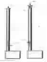
BRIEF DESCRIPTION OF THE DRAWINGSFIG. 1 illustrates the outside view of the igniter of the present invention. FIG. 1A illustrates the front view of the igniter in a retractable position and FIG. 1B illustrated the igniter in the exposed position of the ignition source.
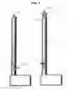
FIG. 2—presents the igniter including the high voltage assembly.
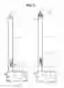
FIG. 3A illustrates the inner view of the igniter in a retractable position while FIG. 3B shows the igniter in the exposed position.
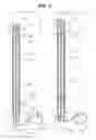
FIGS. 4A and 4B show the inner components of the igniter.
DETAILED DESCRIPTION OF THE INVENTIONThe invention will now be described by reference to the attached Figures.
The present invention relates to a retractable igniter which comprises:
-
- a) an ignition chamber (16);
- b) an ignition rod or electrode (15), wrapped in an electrical insulating block (20), an insulating empty space (21) and a bottom insulating terminal (22), and ended in an electric terminal (23);
- c) an electrical high voltage assembly (13) inside an insulating box (11) and connected to the electric terminal (23) via an electrical cable (17)
- d) an external pilot light pipe (14) encasing an internal pipe (18); and
- e) an activation lever (12).
The electrode (15) within the ignition chamber (16) is only exposed to the environment during the ignition of a combustible source.
During the time of inactivity of the igniter, the electrode (15) remains safeguarded within the ignition chamber (16).
The retractable igniter is a single device for igniting a combustible source, for example a gas pilot pipe, which does not pertain to the scope of this invention and may be any available in the art.
Preferably, the total aperture of the ignition chamber (16) is approximately 55 mm, but it may be sized only enough for the electrode (15) to be exposed to the combustible environment.
The retractable mechanism of the ignition chamber (16) can be either manual or automated. The internal pipe (18) is displaced inside the external pipe (14) by sliding. This displacement towards the ignition chamber (16) is conducted by the activation lever (12), at the time of ignition.
After ignition of the combustible source, the ignition chamber (16) is retracted again, remaining closed far from the combustible source.
While the ignition chamber (16) is in the retracted position, the electrode (15) remains inside of the external pipe (14) and the insulating box (11), which protect it from humidity during the blow down, from high temperatures, and from the grime coming mainly from combustible oil. Preferably the igniter is powered at 110 or 220 VCA and ignition voltage is of about 14 KV, 40 mA rms.
The internal pipe (18) is inserted into the external pipe (14) and is displaced axially. The displacement is limited by the activation lever (12).
The two pipes (18, 14) are centralized axially by means of screw (24) in such a way as to provide a clearance of 1.6 mm axially along them and limiting the displacement towards the ignition chamber (16) by the activation lever (12).
The ignition chamber (16) contains an adjustable screw nut (19) made of stainless steel including the high voltage electric ignition tip (17) of 20 KV.
The activation lever (12), may be made of carbon steel; the isolating box (11) made of aluminum; the pilot light gas pipe (14) made of carbon steel; the electrode (15) made of steel, with the ignition tip made of nickel/chrome;
Claims
1. Retractable igniter comprising: an ignition chamber, an electrode, an electrical high voltage assembly, an external pipe, an internal pipe and an activation lever.
2. Retractable igniter according to claim 1, wherein the activation lever is operated manually.
3. Retractable igniter according to claim 1, wherein the activation lever is operated automatically.
4. (canceled)
5. Retractable igniter according to claim 1, wherein the external pipe, the internal pipe, which is displaced together with the electrode.
6-7. (canceled)
8. Retractable igniter according to claim 1, wherein the electrical high voltage assembly is of about 14 KV, 40 mA rms and includes at least on electric cable linking the electrode and an insulating box.
9-15. (canceled)
Images & Drawings included:
Sources:
- United States Patent and Trademark Office - verify current appl. status at the USPTO↗
Similar patent applications:
- » 20170227218
THERMOSTATICALLY CONTROLLED IGNITION SYSTEM WITH RETRACTABLE IGNITION DEVICE - » 20140220499
Retractable ignition system - » 20170210334
Igniter assembly with retractable piston - » 20180187631
RETRACTABLE ROCKET MOTOR IGNITER - » 20250052424
RETRACTABLE AND EXTENDABLE PORTABLE IGNITORS, IGNITION SYSTEMS, AND ASSOCIATED METHODS
Recent applications in this class:
- » 20240219025 2024-07-04
BURNER IGNITER - » 20230175694 2023-06-08
DC RE-IGNITION SYSTEM FOR A GAS BURNER - » 20230055175 2023-02-23
Spark Ignition Pilot Assembly - » 20220390107 2022-12-08
Ignition device of gas cooktop and gas cooktop - » 20220252266 2022-08-11
Spark ignition pilot assembly - » 20180066845 2018-03-08
Ignition device of burner - » 20140370449 2014-12-18
Dual fuel pilot light burner - » 20140363775 2014-12-11
Flexible gas pipe ignitor - » 20140248570 2014-09-04
INFRARED RAY GAS BURNER - » 20130295510 2013-11-07
Igniter assembly and method for operating
Recent applications for this Assignee:
- » 20250198901 2025-06-19
SYSTEM AND METHOD FOR DETERMINING THE FLUID FLOW WITH TRACER IN FRACTURED ROCK SAMPLE - » 20240279530 2024-08-22
HYDRAULIC CEMENT COMPOSITION, PROCESS AND USE - » 20240229989 2024-07-11
SEALING RING POSITIONING DEVICE - » 20240229973 2024-07-11
PIPELINE HOISTING STRUCTURE AND METHOD - » 20240209691 2024-06-27
System and method for construction and completion of production and injection wells in the pre-salt fields - » 20240175536 2024-05-30
System for protecting coated pipes for on-land and subsea pipelines and the method for protecting pipes - » 20240151124 2024-05-09
Method for expanding the capacity for local storage of chemical products or their solutions in reservoir rock - » 20240133496 2024-04-25
SEALING RING POSITIONING DEVICE - » 20240133488 2024-04-25
PIPELINE HOISTING STRUCTURE AND METHOD - » 20230366793 2023-11-16
Use of nanofluid to remove oil and salts from rock samples in petroleum systems