De-blurring in a digital image system
US20060290784A1
2006-12-28
11/499,806
2006-08-07
✅ Patent granted
US 7,646,403 B2
2010-01-12
-
-
Luong T Nguyen
2027-12-05
Abstract:
A camera system deblurrs an image by detecting a velocity of a camera as an image is captured by an image sensor. A processor interconnected to the image sensor and the velocity detection means processes the sensed image so as to deblurr the image and to output the deblurred image to a printer means.
Assignee:
- Kia Silverbrook 24 🇦🇺 Balmain, New South Wales, Australia
Interested in similar patents?
Get notified when new applications in this technology area are published.
Classification:
H04N5/23248 » CPC main
Details of television systems; Studio circuitry; Studio devices; Studio equipment ; Cameras comprising an electronic image sensor, e.g. digital cameras, video cameras, TV cameras, video cameras, camcorders, webcams, camera modules for embedding in other devices, e.g. mobile phones, computers or vehicles; Television cameras ; Cameras comprising an electronic image sensor, e.g. digital cameras, video cameras, camcorders, webcams, camera modules specially adapted for being embedded in other devices, e.g. mobile phones, computers or vehicles; Devices for controlling television cameras, e.g. remote control ; Control of cameras comprising an electronic image sensor for stable pick-up of the scene in spite of camera body vibration
G03B29/00 » CPC further
Combinations of cameras, projectors or photographic printing apparatus with non-photographic non-optical apparatus, e.g. clocks or weapons; Cameras having the shape of other objects
H04N5/23264 » CPC further
Details of television systems; Studio circuitry; Studio devices; Studio equipment ; Cameras comprising an electronic image sensor, e.g. digital cameras, video cameras, TV cameras, video cameras, camcorders, webcams, camera modules for embedding in other devices, e.g. mobile phones, computers or vehicles; Television cameras ; Cameras comprising an electronic image sensor, e.g. digital cameras, video cameras, camcorders, webcams, camera modules specially adapted for being embedded in other devices, e.g. mobile phones, computers or vehicles; Devices for controlling television cameras, e.g. remote control ; Control of cameras comprising an electronic image sensor for stable pick-up of the scene in spite of camera body vibration Vibration or motion blur correction
H04N5/225 IPC
Details of television systems; Studio circuitry; Studio devices; Studio equipment ; Cameras comprising an electronic image sensor, e.g. digital cameras, video cameras, TV cameras, video cameras, camcorders, webcams, camera modules for embedding in other devices, e.g. mobile phones, computers or vehicles Television cameras ; Cameras comprising an electronic image sensor, e.g. digital cameras, video cameras, camcorders, webcams, camera modules specially adapted for being embedded in other devices, e.g. mobile phones, computers or vehicles
H04N5/228 IPC
Details of television systems; Studio circuitry; Studio devices; Studio equipment ; Cameras comprising an electronic image sensor, e.g. digital cameras, video cameras, TV cameras, video cameras, camcorders, webcams, camera modules for embedding in other devices, e.g. mobile phones, computers or vehicles; Television cameras ; Cameras comprising an electronic image sensor, e.g. digital cameras, video cameras, camcorders, webcams, camera modules specially adapted for being embedded in other devices, e.g. mobile phones, computers or vehicles Circuit details for pick-up tubes
Description
CROSS REFERENCES TO RELATED APPLICATIONSThis is a continuation of U.S. application Ser. No. 09/113,090 filed on Jul. 10, 1998, all of which is herein incorporated by reference.
The following Australian provisional patent applications are hereby incorporated by cross-reference. For the purposes of location and identification, U.S. patent applications identified by their U.S. patent application serial numbers (USSN) are listed alongside the Australian applications from which the U.S. patent applications claim the right of priority.
Ink Jet Printing
A large number of new forms of ink jet printers have been developed to facilitate alternative ink jet technologies for the image processing and data distribution system. Various combinations of ink jet devices can be included in printer devices incorporated as part of the present invention. Australian Provisional Patent Applications relating to these ink jets which are specifically incorporated by cross reference. The serial numbers of respective corresponding U.S. patent applications are also provided for the sake of convenience.
| Australian | US Patent/ | ||
| Provisional | Patent Application | ||
| Number | Filing Date | Title | and Filing Date |
| PO8066 | 15-Jul-97 | Image Creation Method and Apparatus (IJ01) | 6,227,652 |
| (Jul. 10, 1998) | |||
| PO8072 | 15-Jul-97 | Image Creation Method and Apparatus (IJ02) | 6,213,588 |
| (Jul. 10, 1998) | |||
| PO8040 | 15-Jul-97 | Image Creation Method and Apparatus (IJ03) | 6,213,589 |
| (Jul. 10, 1998) | |||
| PO8071 | 15-Jul-97 | Image Creation Method and Apparatus (IJ04) | 6,231,163 |
| (Jul. 10, 1998) | |||
| PO8047 | 15-Jul-97 | Image Creation Method and Apparatus (IJ05) | 6,247,795 |
| (Jul. 10, 1998) | |||
| PO8035 | 15-Jul-97 | Image Creation Method and Apparatus (IJ06) | 6,394,581 |
| (Jul. 10, 1998) | |||
| PO8044 | 15-Jul-97 | Image Creation Method and Apparatus (IJ07) | 6,244,691 |
| (Jul. 10, 1998) | |||
| PO8063 | 15-Jul-97 | Image Creation Method and Apparatus (IJ08) | 6,257,704 |
| (Jul. 10, 1998) | |||
| PO8057 | 15-Jul-97 | Image Creation Method and Apparatus (IJ09) | 6,416,168 |
| (Jul. 10, 1998) | |||
| PO8056 | 15-Jul-97 | Image Creation Method and Apparatus (IJ10) | 6,220,694 |
| (Jul. 10, 1998) | |||
| PO8069 | 15-Jul-97 | Image Creation Method and Apparatus (IJ11) | 6,257,705 |
| (Jul. 10, 1998) | |||
| PO8049 | 15-Jul-97 | Image Creation Method and Apparatus (IJ12) | 6,247,794 |
| (Jul. 10, 1998) | |||
| PO8036 | 15-Jul-97 | Image Creation Method and Apparatus (IJ13) | 6,234,610 |
| (Jul. 10, 1998) | |||
| PO8048 | 15-Jul-97 | Image Creation Method and Apparatus (IJ14) | 6,247,793 |
| (Jul. 10, 1998) | |||
| PO8070 | 15-Jul-97 | Image Creation Method and Apparatus (IJ15) | 6,264,306 |
| (Jul. 10, 1998) | |||
| PO8067 | 15-Jul-97 | Image Creation Method and Apparatus (IJ16) | 6,241,342 |
| (Jul. 10, 1998) | |||
| PO8001 | 15-Jul-97 | Image Creation Method and Apparatus (IJ17) | 6,247,792 |
| (Jul. 10, 1998) | |||
| PO8038 | 15-Jul-97 | Image Creation Method and Apparatus (IJ18) | 6,264,307 |
| (Jul. 10, 1998) | |||
| PO8033 | 15-Jul-97 | Image Creation Method and Apparatus (IJ19) | 6,254,220 |
| (Jul. 10, 1998) | |||
| PO8002 | 15-Jul-97 | Image Creation Method and Apparatus (IJ20) | 6,234,611 |
| (Jul. 10, 1998) | |||
| PO8068 | 15-Jul-97 | Image Creation Method and Apparatus (IJ21) | 6,302,528) |
| (Jul. 10, 1998) | |||
| PO8062 | 15-Jul-97 | Image Creation Method and Apparatus (IJ22) | 6,283,582 |
| (Jul. 10, 1998) | |||
| PO8034 | 15-Jul-97 | Image Creation Method and Apparatus (IJ23) | 6,239,821 |
| (Jul. 10, 1998) | |||
| PO8039 | 15-Jul-97 | Image Creation Method and Apparatus (IJ24) | 6,338,547 |
| (Jul. 10, 1998) | |||
| PO8041 | 15-Jul-97 | Image Creation Method and Apparatus (IJ25) | 6,247,796 |
| (Jul. 10, 1998) | |||
| PO8004 | 15-Jul-97 | Image Creation Method and Apparatus (IJ26) | 6,557,977 |
| (Jul. 10, 1998) | |||
| PO8037 | 15-Jul-97 | Image Creation Method and Apparatus (IJ27) | 6,390,603 |
| (Jul. 10, 1998) | |||
| PO8043 | 15-Jul-97 | Image Creation Method and Apparatus (IJ28) | 6,362,843 |
| (Jul. 10, 1998) | |||
| PO8042 | 15-Jul-97 | Image Creation Method and Apparatus (IJ29) | 6,293,653 |
| (Jul. 10, 1998) | |||
| PO8064 | 15-Jul-97 | Image Creation Method and Apparatus (IJ30) | 6,312,107 |
| (Jul. 10, 1998) | |||
| PO9389 | 23-Sep-97 | Image Creation Method and Apparatus (IJ31) | 6,227,653 |
| (Jul. 10, 1998) | |||
| PO9391 | 23-Sep-97 | Image Creation Method and Apparatus (IJ32) | 6,234,609 |
| (Jul. 10, 1998) | |||
| PP0888 | 12-Dec-97 | Image Creation Method and Apparatus (IJ33) | 6,238,040 |
| (Jul. 10, 1998) | |||
| PP0891 | 12-Dec-97 | Image Creation Method and Apparatus (IJ34) | 6,188,415 |
| (Jul. 10, 1998) | |||
| PP0890 | 12-Dec-97 | Image Creation Method and Apparatus (IJ35) | 6,227,654 |
| (Jul. 10, 1998) | |||
| PP0873 | 12-Dec-97 | Image Creation Method and Apparatus (IJ36) | 6,209,989 |
| (Jul. 10, 1998) | |||
| PP0993 | 12-Dec-97 | Image Creation Method and Apparatus (IJ37) | 6,247,791 |
| (Jul. 10, 1998) | |||
| PP0890 | 12-Dec-97 | Image Creation Method and Apparatus (IJ38) | 6,336,710 |
| (Jul. 10, 1998) | |||
| PP1398 | 19-Jan-98 | An Image Creation Method and Apparatus | 6,217,153 |
| (IJ39) | (Jul. 10, 1998) | ||
| PP2592 | 25-Mar-98 | An Image Creation Method and Apparatus | 6,416,167 |
| (IJ40) | (Jul. 10, 1998) | ||
| PP2593 | 25-Mar-98 | Image Creation Method and Apparatus (IJ41) | 6,243,113 |
| (Jul. 10, 1998) | |||
| PP3991 | 9-Jun-98 | Image Creation Method and Apparatus (IJ42) | 6,283,581 |
| (Jul. 10, 1998) | |||
| PP3987 | 9-Jun-98 | Image Creation Method and Apparatus (IJ43) | 6,247,790 |
| (Jul. 10, 1998) | |||
| PP3985 | 9-Jun-98 | Image Creation Method and Apparatus (IJ44) | 6,260,953 |
| (Jul. 10, 1998) | |||
| PP3983 | 9-Jun-98 | Image Creation Method and Apparatus (IJ45) | 6,267,469 |
| (Jul. 10, 1998) | |||
Ink Jet Manufacturing
Further, the present application may utilize advanced semiconductor fabrication techniques in the construction of large arrays of ink jet printers. Suitable manufacturing techniques are described in the following Australian provisional patent specifications incorporated here by cross-reference. The serial numbers of respective corresponding U.S. patent applications are also provided for the sake of convenience.
| Australian | US Patent/ | ||
| Provisional | Patent Application | ||
| Number | Filing Date | Title | and Filing Date |
| PO7935 | 15-Jul-97 | A Method of Manufacture of an Image Creation | 6,224,780 |
| Apparatus (IJM01) | (Jul. 10, 1998) | ||
| PO7936 | 15-Jul-97 | A Method of Manufacture of an Image Creation | 6,235,212 |
| Apparatus (IJM02) | (Jul. 10, 1998) | ||
| PO7937 | 15-Jul-97 | A Method of Manufacture of an Image Creation | 6,280,643 |
| Apparatus (IJM03) | (Jul. 10, 1998) | ||
| PO8061 | 15-Jul-97 | A Method of Manufacture of an Image Creation | 6,284,147 |
| Apparatus (IJM04) | (Jul. 10, 1998) | ||
| PO8054 | 15-Jul-97 | A Method of Manufacture of an Image Creation | 6,214,244 |
| Apparatus (IJM05) | (Jul. 10, 1998) | ||
| PO8065 | 15-Jul-97 | A Method of Manufacture of an Image Creation | 6,071,750 |
| Apparatus (IJM06) | (Jul. 10, 1998) | ||
| PO8055 | 15-Jul-97 | A Method of Manufacture of an Image Creation | 6,267,905 |
| Apparatus (IJM07) | (Jul. 10, 1998) | ||
| PO8053 | 15-Jul-97 | A Method of Manufacture of an Image Creation | 6,251,298 |
| Apparatus (IJM08) | (Jul. 10, 1998) | ||
| PO8078 | 15-Jul-97 | A Method of Manufacture of an Image Creation | 6,258,285 |
| Apparatus (IJM09) | (Jul. 10, 1998) | ||
| PO7933 | 15-Jul-97 | A Method of Manufacture of an Image Creation | 6,225,138 |
| Apparatus (IJM10) | (Jul. 10, 1998) | ||
| PO7950 | 15-Jul-97 | A Method of Manufacture of an Image Creation | 6,241,904 |
| Apparatus (IJM11) | (Jul. 10, 1998) | ||
| PO7949 | 15-Jul-97 | A Method of Manufacture of an Image Creation | 6,299,786 |
| Apparatus (IJM12) | (Jul. 10, 1998) | ||
| PO8060 | 15-Jul-97 | A Method of Manufacture of an Image Creation | 09/113,124 |
| Apparatus (IJM13) | (Jul. 10, 1998) | ||
| PO8059 | 15-Jul-97 | A Method of Manufacture of an Image Creation | 6,231,773 |
| Apparatus (IJM14) | (Jul. 10, 1998) | ||
| PO8073 | 15-Jul-97 | A Method of Manufacture of an Image Creation | 6,190,931 |
| Apparatus (IJM15) | (Jul. 10, 1998) | ||
| PO8076 | 15-Jul-97 | A Method of Manufacture of an Image Creation | 6,248,249 |
| Apparatus (IJM16) | (Jul. 10, 1998) | ||
| PO8075 | 15-Jul-97 | A Method of Manufacture of an Image Creation | 6,290,862 |
| Apparatus (IJM17) | (Jul. 10, 1998) | ||
| PO8079 | 15-Jul-97 | A Method of Manufacture of an Image Creation | 6,241,906 |
| Apparatus (IJM18) | (Jul. 10, 1998) | ||
| PO8050 | 15-Jul-97 | A Method of Manufacture of an Image Creation | 6,565,762 |
| Apparatus (IJM19) | (Jul. 10, 1998) | ||
| PO8052 | 15-Jul-97 | A Method of Manufacture of an Image Creation | 6,241,905 |
| Apparatus (IJM20) | (Jul. 10, 1998) | ||
| PO7948 | 15-Jul-97 | A Method of Manufacture of an Image Creation | 6,451,216 |
| Apparatus (IJM21) | (Jul. 10, 1998) | ||
| PO7951 | 15-Jul-97 | A Method of Manufacture of an Image Creation | 6,231,772 |
| Apparatus (IJM22) | (Jul. 10, 1998) | ||
| PO8074 | 15-Jul-97 | A Method of Manufacture of an Image Creation | 6,274,056 |
| Apparatus (IJM23) | (Jul. 10, 1998) | ||
| PO7941 | 15-Jul-97 | A Method of Manufacture of an Image Creation | 6,290,861 |
| Apparatus (IJM24) | (Jul. 10, 1998) | ||
| PO8077 | 15-Jul-97 | A Method of Manufacture of an Image Creation | 6,248,248 |
| Apparatus (IJM25) | (Jul. 10, 1998) | ||
| PO8058 | 15-Jul-97 | A Method of Manufacture of an Image Creation | 6,306,671 |
| Apparatus (IJM26) | (Jul. 10, 1998) | ||
| PO8051 | 15-Jul-97 | A Method of Manufacture of an Image Creation | 6,331,258 |
| Apparatus (IJM27) | (Jul. 10, 1998) | ||
| PO8045 | 15-Jul-97 | A Method of Manufacture of an Image Creation | 6,110,754 |
| Apparatus (IJM28) | (Jul. 10, 1998) | ||
| PO7952 | 15-Jul-97 | A Method of Manufacture of an Image Creation | 6,294,101 |
| Apparatus (IJM29) | (Jul. 10, 1998) | ||
| PO8046 | 15-Jul-97 | A Method of Manufacture of an Image Creation | 6,416,679 |
| Apparatus (IJM30) | (Jul. 10, 1998) | ||
| PO8503 | 11-Aug-97 | A Method of Manufacture of an Image Creation | 6,264,849 |
| Apparatus (IJM30a) | (Jul. 10, 1998) | ||
| PO9390 | 23-Sep-97 | A Method of Manufacture of an Image Creation | 6,254,793 |
| Apparatus (IJM31) | (Jul. 10, 1998) | ||
| PO9392 | 23-Sep-97 | A Method of Manufacture of an Image Creation | 6,235,211 |
| Apparatus (IJM32) | (Jul. 10, 1998) | ||
| PP0889 | 12-Dec-97 | A Method of Manufacture of an Image Creation | 6,235,211 |
| Apparatus (IJM35) | (Jul. 10, 1998) | ||
| PP0887 | 12-Dec-97 | A Method of Manufacture of an Image Creation | 6,264,850 |
| Apparatus (IJM36) | (Jul. 10, 1998) | ||
| PP0882 | 12-Dec-97 | A Method of Manufacture of an Image Creation | 6,258,284 |
| Apparatus (IJM37) | (Jul. 10, 1998) | ||
| PP0874 | 12-Dec-97 | A Method of Manufacture of an Image Creation | 6,258,284 |
| Apparatus (IJM38) | (Jul. 10, 1998) | ||
| PP1396 | 19-Jan-98 | A Method of Manufacture of an Image Creation | 6,228,668 |
| Apparatus (IJM39) | (Jul. 10, 1998) | ||
| PP2591 | 25-Mar-98 | A Method of Manufacture of an Image Creation | 6,180,427 |
| Apparatus (IJM41) | (Jul. 10, 1998) | ||
| PP3989 | 9-Jun-98 | A Method of Manufacture of an Image Creation | 6,171,875 |
| Apparatus (IJM40) | (Jul. 10, 1998) | ||
| PP3990 | 9-Jun-98 | A Method of Manufacture of an Image Creation | 6,267,904 |
| Apparatus (IJM42) | (Jul. 10, 1998) | ||
| PP3986 | 9-Jun-98 | A Method of Manufacture of an Image Creation | 6,245,247 |
| Apparatus (IJM43) | (Jul. 10, 1998) | ||
| PP3984 | 9-Jun-98 | A Method of Manufacture of an Image Creation | 6,245,247 |
| Apparatus (IJM44) | (Jul. 10, 1998) | ||
| PP3982 | 9-Jun-98 | A Method of Manufacture of an Image Creation | 6,231,148 |
| Apparatus (IJM45) | (Jul. 10, 1998) | ||
Fluid Supply
Further, the present application may utilize an ink delivery system to the ink jet head. Delivery systems relating to the supply of ink to a series of ink jet nozzles are described in the following Australian provisional patent specifications, the disclosure of which are hereby incorporated by cross-reference. The serial numbers of respective corresponding U.S. patent applications are also provided for the sake of convenience.
| Australian | US Patent/Patent | ||
| Provisional | Application and | ||
| Number | Filing Date | Title | Filing Date |
| PO8003 | 15-Jul-97 | Supply Method and | 6,350,023 |
| Apparatus (F1) | (Jul. 10, 1998) | ||
| PO8005 | 15-Jul-97 | Supply Method and | 6,318,849 |
| Apparatus (F2) | (Jul. 10, 1998) | ||
| PO9404 | 23-Sep-97 | A Device and Method | 09/113,101 |
| (F3) | (Jul. 10, 1998) | ||
MEMS Technology
Further, the present application may utilize advanced semiconductor microelectromechanical techniques in the construction of large arrays of ink jet printers. Suitable microelectromechanical techniques are described in the following Australian provisional patent specifications incorporated here by cross-reference. The serial numbers of respective corresponding U.S. patent applications are also provided for the sake of convenience.
| Australian | US Patent/Patent | ||
| Provisional | Application and | ||
| Number | Filing Date | Title | Filing Date |
| PO7943 | 15-Jul-97 | A device (MEMS01) | |
| PO8006 | 15-Jul-97 | A device (MEMS02) | 6,087,638 |
| (Jul. 10, 1998) | |||
| PO8007 | 15-Jul-97 | A device (MEMS03) | 09/113,093 |
| (Jul. 10, 1998) | |||
| PO8008 | 15-Jul-97 | A device (MEMS04) | 6,340,222 |
| (Jul. 10, 1998) | |||
| PO8010 | 15-Jul-97 | A device (MEMS05) | 6,041,600 |
| (Jul. 10, 1998) | |||
| PO8011 | 15-Jul-97 | A device (MEMS06) | 6,299,300 |
| (Jul. 10, 1998) | |||
| PO7947 | 15-Jul-97 | A device (MEMS07) | 6,067,797 |
| (Jul. 10, 1998) | |||
| PO7945 | 15-Jul-97 | A device (MEMS08) | Not filed |
| PO7944 | 15-Jul-97 | A device (MEMS09) | 6,286,935 |
| (Jul. 10, 1998) | |||
| PO7946 | 15-Jul-97 | A device (MEMS10) | 6,044,646 |
| (Jul. 10, 1998) | |||
| PO9393 | 23-Sep-97 | A Device and Method | 09/113,065 |
| (MEMS11) | (Jul. 10, 1998) | ||
| PP0875 | 12-Dec-97 | A Device (MEMS12) | 09/113,078 |
| (Jul. 10, 1998) | |||
| PP0894 | 12-Dec-97 | A Device and Method | 09/113,075 |
| (MEMS13) | (Jul. 10, 1998) | ||
IR Technologies
Further, the present application may include the utilization of a disposable camera system such as those described in the following Australian provisional patent specifications incorporated here by cross-reference. The serial numbers of respective corresponding U.S. patent applications are also provided for the sake of convenience.
| Australian | US Patent/Patent | ||
| Provisional | Application and | ||
| Number | Filing Date | Title | Filing Date |
| PP0895 | 12-Dec-97 | An Image Creation Method and Apparatus | 6,231,148 |
| (IR01) | (Jul. 10, 1998) | ||
| PP0870 | 12-Dec-97 | A Device and Method (IR02) | 09/113,106 |
| (Jul. 10, 1998) | |||
| PP0869 | 12-Dec-97 | A Device and Method (IR04) | 6,293,658 |
| (Jul. 10, 1998) | |||
| PP0887 | 12-Dec-97 | Image Creation Method and Apparatus | 6,614,560 |
| (IR05) | (Jul. 10, 1998) | ||
| PP0885 | 12-Dec-97 | An Image Production System (IR06) | 6,238,033 |
| (Jul. 10, 1998) | |||
| PP0884 | 12-Dec-97 | Image Creation Method and Apparatus | 6,312,070 |
| (IR10) | (Jul. 10, 1998) | ||
| PP0886 | 12-Dec-97 | Image Creation Method and Apparatus | 6,238,111 |
| (IR12) | (Jul. 10, 1998) | ||
| PP0871 | 12-Dec-97 | A Device and Method (IR13) | 09/113,086 |
| (Jul. 10, 1998) | |||
| PP0876 | 12-Dec-97 | An Image Processing Method and | 09/113,094 |
| Apparatus (IR14) | (Jul. 10, 1998) | ||
| PP0877 | 12-Dec-97 | A Device and Method (IR16) | 6,378,970 |
| (Jul. 10, 1998 | |||
| PP0878 | 12-Dec-97 | A Device and Method (IR17) | 6,196,739 |
| (Jul. 10, 1998) | |||
| PP0879 | 12-Dec-97 | A Device and Method (IR18) | 09/112,774 |
| (Jul. 10, 1998) | |||
| PP0883 | 12-Dec-97 | A Device and Method (IR19) | 6,270,182 |
| (Jul. 10, 1998) | |||
| PP0880 | 12-Dec-97 | A Device and Method (IR20) | 6,152,619 |
| (Jul. 10, 1998) | |||
| PP0881 | 12-Dec-97 | A Device and Method (IR21) | 09/113,092 |
| (Jul. 10, 1998) | |||
DotCard Technologies
Further, the present application may include the utilization of a data distribution system such as that described in the following Australian provisional patent specifications incorporated here by cross-reference. The serial numbers of respective corresponding U.S. patent applications are also provided for the sake of convenience.
| Australian | US Patent/Patent | ||
| Provisional | Application and | ||
| Number | Filing Date | Title | Filing Date |
| PP2370 | 16-Mar-98 | Data Processing Method | 09/112,781 |
| and Apparatus (Dot01) | (Jul. 10, 1998) | ||
| PP2371 | 16-Mar-98 | Data Processing Method | 09/113,052 |
| and Apparatus (Dot02) | (Jul. 10, 1998 | ||
Artcam Technologies
Further, the present application may include the utilization of camera and data processing techniques such as an Artcam type device as described in the following Australian provisional patent specifications incorporated here by cross-reference. The serial numbers of respective corresponding U.S. patent applications are also provided for the sake of convenience.
| Australian | US Patent/ | ||
| Provisional | Patent Application and | ||
| Number | Filing Date | Title | Filing Date |
| PO7991 | 15-Jul-97 | Image Processing Method and Apparatus | 09/113,060 |
| (ART01) | (Jul. 10, 1998) | ||
| PO7988 | 15-Jul-97 | Image Processing Method and Apparatus | 6,476,863 |
| (ART02) | (Jul. 10, 1998) | ||
| PO7993 | 15-Jul-97 | Image Processing Method and Apparatus | 09/113,073 |
| (ART03) | (Jul. 10, 1998) | ||
| PO9395 | 23-Sep-97 | Data Processing Method and Apparatus | 6,322,181 |
| (ART04) | (Jul. 10, 1998) | ||
| PO8017 | 15-Jul-97 | Image Processing Method and Apparatus | 6,597,817 |
| (ART06) | (Jul. 10, 1998) | ||
| PO8014 | 15-Jul-97 | Media Device (ART07) | 6,227,648 |
| (Jul. 10, 1998) | |||
| PO8025 | 15-Jul-97 | Image Processing Method and Apparatus | 09/112,750 |
| (ART08) | (Jul. 10, 1998) | ||
| PO8032 | 15-Jul-97 | Image Processing Method and Apparatus | 6,690,419 |
| (ART09) | (Jul. 10, 1998) | ||
| PO7999 | 15-Jul-97 | Image Processing Method and Apparatus | 09/112,743 |
| (ART10) | (Jul. 10, 1998) | ||
| PO7998 | 15-Jul-97 | Image Processing Method and Apparatus | 09/112,742 |
| (ART11) | (Jul. 10, 1998) | ||
| PO8031 | 15-Jul-97 | Image Processing Method and Apparatus | 09/112,741 |
| (ART12) | (Jul. 10, 1998) | ||
| PO8030 | 15-Jul-97 | Media Device (ART13) | 6,196,541 |
| (Jul. 10, 1998) | |||
| PO7997 | 15-Jul-97 | Media Device (ART15) | 6,195,150 |
| (Jul. 10, 1998) | |||
| PO7979 | 15-Jul-97 | Media Device (ART16) | 6,362,868 |
| (Jul. 10, 1998) | |||
| PO8015 | 15-Jul-97 | Media Device (ART17) | 09/112,738 |
| (Jul. 10, 1998) | |||
| PO7978 | 15-Jul-97 | Media Device (ART18) | 09/113,067 |
| (Jul. 10, 1998) | |||
| PO7982 | 15-Jul-97 | Data Processing Method and Apparatus | 6,431,669 |
| (ART19) | (Jul. 10, 1998 | ||
| PO7989 | 15-Jul-97 | Data Processing Method and Apparatus | 6,362,869 |
| (ART20) | (Jul. 10, 1998 | ||
| PO8019 | 15-Jul-97 | Media Processing Method and Apparatus | 6,472,052 |
| (ART21) | (Jul. 10, 1998 | ||
| PO7980 | 15-Jul-97 | Image Processing Method and Apparatus | 6,356,715 |
| (ART22) | (Jul. 10, 1998) | ||
| PO8018 | 15-Jul-97 | Image Processing Method and Apparatus | 09/112,777 |
| (ART24) | (Jul. 10, 1998) | ||
| PO7938 | 15-Jul-97 | Image Processing Method and Apparatus | 6,636,216 |
| (ART25) | (Jul. 10, 1998) | ||
| PO8016 | 15-Jul-97 | Image Processing Method and Apparatus | 6,366,693 |
| (ART26) | (Jul. 10, 1998) | ||
| PO8024 | 15-Jul-97 | Image Processing Method and Apparatus | 6,329,990 |
| (ART27) | (Jul. 10, 1998) | ||
| PO7940 | 15-Jul-97 | Data Processing Method and Apparatus | 09/113,072 |
| (ART28) | (Jul. 10, 1998) | ||
| PO7939 | 15-Jul-97 | Data Processing Method and Apparatus | 6,459,495 |
| (ART29) | (Jul. 10, 1998) | ||
| PO8501 | 11-Aug-97 | Image Processing Method and Apparatus | 6,137,500 |
| (ART30) | (Jul. 10, 1998) | ||
| PO8500 | 11-Aug-97 | Image Processing Method and Apparatus | 6,690,416 |
| (ART31) | (Jul. 10, 1998) | ||
| PO7987 | 15-Jul-97 | Data Processing Method and Apparatus | 09/113,071 |
| (ART32) | (Jul. 10, 1998) | ||
| PO8022 | 15-Jul-97 | Image Processing Method and Apparatus | 6,398,328 |
| (ART33) | (Jul. 10, 1998 | ||
| PO8497 | 11-Aug-97 | Image Processing Method and Apparatus | 09/113,090 |
| (ART34) | (Jul. 10, 1998) | ||
| PO8020 | 15-Jul-97 | Data Processing Method and Apparatus | 6,431,704 |
| (ART38) | (Jul. 10, 1998 | ||
| PO8023 | 15-Jul-97 | Data Processing Method and Apparatus | 09/113,222 |
| (ART39) | (Jul. 10, 1998) | ||
| PO8504 | 11-Aug-97 | Image Processing Method and Apparatus | 09/112,786 |
| (ART42) | (Jul. 10, 1998) | ||
| PO8000 | 15-Jul-97 | Data Processing Method and Apparatus | 6,415,054 |
| (ART43) | (Jul. 10, 1998) | ||
| PO7977 | 15-Jul-97 | Data Processing Method and Apparatus | 09/112,782 |
| (ART44) | (Jul. 10, 1998) | ||
| PO7934 | 15-Jul-97 | Data Processing Method and Apparatus | 6,665,454 |
| (ART45) | (Jul. 10, 1998) | ||
| PO7990 | 15-Jul-97 | Data Processing Method and Apparatus | 09/113,059 |
| (ART46) | (Jul. 10, 1998) | ||
| PO8499 | 11-Aug-97 | Image Processing Method and Apparatus | 6,486,886 |
| (ART47) | (Jul. 10, 1998) | ||
| PO8502 | 11-Aug-97 | Image Processing Method and Apparatus | 6,381,361 |
| (ART48) | (Jul. 10, 1998) | ||
| PO7981 | 15-Jul-97 | Data Processing Method and Apparatus | 6,317,192 |
| (ART50) | (Jul. 10, 1998 | ||
| PO7986 | 15-Jul-97 | Data Processing Method and Apparatus | 09/113,057 |
| (ART51) | (Jul. 10, 1998) | ||
| PO7983 | 15-Jul-97 | Data Processing Method and Apparatus | 09/113,054 |
| (ART52) | (Jul. 10, 1998) | ||
| PO8026 | 15-Jul-97 | Image Processing Method and Apparatus | 6,646,757 |
| (ART53) | (Jul. 10, 1998) | ||
| PO8027 | 15-Jul-97 | Image Processing Method and Apparatus | 09/112,759 |
| (ART54) | (Jul. 10, 1998) | ||
| PO8028 | 15-Jul-97 | Image Processing Method and Apparatus | 6,624,848 |
| (ART56) | (Jul. 10, 1998) | ||
| PO9394 | 23-Sep-97 | Image Processing Method and Apparatus | 6,357,135 |
| (ART57) | (Jul. 10, 1998 | ||
| PO9396 | 23-Sep-97 | Data Processing Method and Apparatus | 09/113,107 |
| (ART58) | (Jul. 10, 1998) | ||
| PO9397 | 23-Sep-97 | Data Processing Method and Apparatus | 6,271,931 |
| (ART59) | (Jul. 10, 1998) | ||
| PO9398 | 23-Sep-97 | Data Processing Method and Apparatus | 6,353,772 |
| (ART60) | (Jul. 10, 1998) | ||
| PO9399 | 23-Sep-97 | Data Processing Method and Apparatus | 6,106,147 |
| (ART61) | (Jul. 10, 1998) | ||
| PO9400 | 23-Sep-97 | Data Processing Method and Apparatus | 6,665,008 |
| (ART62) | (Jul. 10, 1998) | ||
| PO9401 | 23-Sep-97 | Data Processing Method and Apparatus | 6,304,291 |
| (ART63) | (Jul. 10, 1998) | ||
| PO9402 | 23-Sep-97 | Data Processing Method and Apparatus | 09/112,788 |
| (ART64) | (Jul. 10, 1998) | ||
| PO9403 | 23-Sep-97 | Data Processing Method and Apparatus | 6,305,770 |
| (ART65) | (Jul. 10, 1998) | ||
| PO9405 | 23-Sep-97 | Data Processing Method and Apparatus | 6,289,262 |
| (ART66) | (Jul. 10, 1998) | ||
| PP0959 | 16-Dec-97 | A Data Processing Method and Apparatus | 6,315,200 |
| (ART68) | (Jul. 10, 1998) | ||
| PP1397 | 19-Jan-98 | A Media Device (ART69) | 6,217,165 |
| (Jul. 10, 1998) | |||
The present invention relates to digital image processing and in particular discloses A Camera System Having Motion Deblurring Means. Further the present invention relates to the field of digital image cameras and in particular discloses a camera system having motion blur compensating means.
BACKGROUND OF THE INVENTIONMotion blur in the taking of images is a common significant problem. The motion blur normally occurs as a result of movement of the camera while taking the picture or otherwise as a result of movement of objects within an image.
As a result of motion blur, it is often the case that the image taken is non optimal.
SUMMARY OF THE INVENTIONIt is an object of the present invention to provide a camera system having the ability to overcome the effects of motion blur.
In accordance with the first aspect of the present invention there is provided a camera system for outputting deblurred images, said system comprising;
-
- an image sensor for sensing an image; a velocity detection means for determining any motion of said image relative to an external environment and to produce a velocity output indicative thereof; a processor means interconnected to said image sensor and said velocity detection means and adapted to process said sensed image utilising the velocity output so as to deblurr said image and to output said deblurred image.
Preferably, the camera system is connected to a printer means for immediate output of said deblurred image and is a portable handheld unit. The velocity detection means can comprise an accelerometer such as a micro-electro mechanical (MEMS) device.
BRIEF DESCRIPTION OF THE DRAWINGSNotwithstanding any other forms which may fall within the scope of the present invention, preferred forms of the invention will now be described, by way of example only, with reference to the accompanying drawing in which:
FIG. 1 illustrates a schematic implementation of the preferred embodiment; and
FIG. 2 is a schematic block diagram of the main Artcam electronic components (as reproduced from FIG. 2 of Australian Provisional Patent Application No. PO7991).
As described in Australian Provisional Patent Application No. PO7991, the camera system incorporates an Artcard linear sensor 34 which converts the Artcard data image to electrical signals, which are communicated to the ACP. The linear image sensor is illustrated in FIG. 2, which is a reproduction of FIG. 2 of Australian Provisional Patent Application No. PO7991. The linear image sensor can be fabricated using either CCD or APS CMOS technology. The active length of the linear image sensor is 50 mm, equal to the width of the data array on the Artcard. To satisfy Nyquist's sampling theorem, the resolution of the linear image sensor must be at least twice the highest spatial frequency of the Artcard optical image reaching the linear image sensor. In practice, data detection is easier if the linear image sensor resolution is substantially above this. A resolution of 4800 dpi (189 dpmm) is chosen, giving a total of 9,450 pixels. This resolution requires a pixel sensor pitch of 5.3 [mu]m. This can readily be achieved by using four staggered rows of 20 [mu]m pixel sensors.
The linear image sensor is mounted in a special package which includes an LED to illuminate the Artcard via a light-pipe.
The Artcard reader light-pipe can be a molded light-pipe which has several functions:
1. It diffuses the light from the LED over the width of the card using total internal reflection facets.
2. It focuses the light onto a 16 [mu]m wide strip of the Artcard using an integrated cylindrical lens.
3. It focuses light reflected from the Artcard onto the linear image sensor pixels using a molded array of microlenses.
DESCRIPTION OF PREFERRED EMBODIMENTSThe preferred embodiment is preferably implemented through suitable programming of a hand held camera device such as that described in Australian Provisional Patent Application No. PO7991 filed 15 Jul., 1997 entitled “Image Processing Method and Apparatus (ART01)”, in addition to Australian Provisional Patent Application entitled “Image Processing Method and Apparatus (ART01a)” filed concurrently herewith by the present applicant, the content of which is hereby specifically incorporated by cross reference.
The aforementioned patent specifications disclose a camera system, hereinafter known as an “Artcam” type camera, wherein sensed images can be directly printed out by an internal Artcam portable camera unit. Further, the aforementioned specification discloses means and methods for performing various manipulations on images captured by the camera sensing device leading to the production of various effects in any output image. The manipulations are disclosed to be highly flexible in nature and can be implemented through the insertion into the Artcam of cards having encoded thereon various instructions for the manipulation of images, the cards hereinafter being known as “Artcards”. The Artcam further has significant onboard processing power by an Artcam Central Processor unit (ACP) which is interconnected to a memory device for the storage of important data and images.
In the preferred embodiment, the Artcam device is modified so as to include a two dimensional motion sensor. The motion sensor can comprise a small micro-electro mechanical system (MEMS) device or other suitable device able to detect motion in two axes. The motion sensor can be mounted on the camera device and its output monitored by the Artcam central processor device which is disclosed in the afore-mentioned patent specifications.
Turning now to FIG. 1, there is illustrated a schematic of the preferred arrangement of the preferred embodiment. The accelerometer 1 outputs to the Artcard processor 2 which also receives the blurred sensed image from the CCD device. The Artcard processor 2 utilises the accelerometer readings so as to determine a likely angular velocity of the camera when the picture was taken.
This velocity factor is then utilised by a suitably programmed Artcard processor 2 to apply a deblurring function to the blurred sensed image 3 thereby outputting a deblurred output image 4. The programming of the Artcard processor 2 so as to perform the deblurring can utilise standard algorithms known to those skilled in the art of computer programming and digital image restoration. For example, reference is made to the “Selected Papers on Digital Image Restoration”, M. Ibrahim Sezan, Editor, SPIE Milestone series, volume 74, and in particular the reprinted paper at pages 167-175 thereof. Further, simplified techniques are shown in the “Image Processing Handbook”, second edition, by John C. Russ, published by CRC Press at pages 336-341 thereof.
It would be therefore obvious to the person skilled in the art that many different techniques for motion blur removal can be utilised in the preferred embodiment. Additionally, other forms of motion sensors may be provided. Once the input image has been deblurred, the image is then able to be printed out by the Artcam device in accordance with the techniques as discussed in the afore-mentioned patent specification.
It would be appreciated by a person skilled in the art that numerous variations and/or modifications may be made to the present invention as shown in the specific embodiment without departing from the spirit or scope of the invention as broadly described. The present embodiment is, therefore, to be considered in all respects to be illustrative and not restrictive.
Ink Jet Technologies
The embodiments of the invention use an ink jet printer type device. Of course many different devices could be used. However presently popular ink jet printing technologies are unlikely to be suitable.
The most significant problem with thermal inkjet is power consumption. This is approximately 100 times that required for high speed, and stems from the energy-inefficient means of drop ejection. This involves the rapid boiling of water to produce a vapor bubble which expels the ink. Water has a very high heat capacity, and must be superheated in thermal inkjet applications. This leads to an efficiency of around 0.02%, from electricity input to drop momentum (and increased surface area) out.
The most significant problem with piezoelectric inkjet is size and cost. Piezoelectric crystals have a very small deflection at reasonable drive voltages, and therefore require a large area for each nozzle. Also, each piezoelectric actuator must be connected to its drive circuit on a separate substrate. This is not a significant problem at the current limit of around 300 nozzles per print head, but is a major impediment to the fabrication of pagewidth print heads with 19,200 nozzles.
Ideally, the inkjet technologies used meet the stringent requirements of in-camera digital color printing and other high quality, high speed, low cost printing applications. To meet the requirements of digital photography, new inkjet technologies have been created. The target features include:
low power (less than 10 Watts)
high resolution capability (1,600 dpi or more)
photographic quality output
low manufacturing cost
small size (pagewidth times minimum cross section)
high speed (<2 seconds per page).
All of these features can be met or exceeded by the inkjet systems described below with differing levels of difficulty. Forty-five different inkjet technologies have been developed by the Assignee to give a wide range of choices for high volume manufacture. These technologies form part of separate applications assigned to the present Assignee as set out in the table under the heading “Cross References to Related Applications”.
The inkjet designs shown here are suitable for a wide range of digital printing systems, from battery powered one-time use digital cameras, through to desktop and network printers, and through to commercial printing systems.
For ease of manufacture using standard process equipment, the printhead is designed to be a monolithic 0.5 micron CMOS chip with MEMS post processing. For color photographic applications, the printhead is 100 mm long, with a width which depends upon the inkjet type. The smallest printhead designed is IJ38, which is 0.35 mm wide, giving a chip area of 35 square mm. The printheads each contain 19,200 nozzles plus data and control circuitry.
Ink is supplied to the back of the printhead by injection molded plastic ink channels. The molding requires 50 micron features, which can be created using a lithographically micromachined insert in a standard injection molding tool. Ink flows through holes etched through the wafer to the nozzle chambers fabricated on the front surface of the wafer. The printhead is connected to the camera circuitry by tape automated bonding.
Tables of Drop-on-Demand Inkjets
Eleven important characteristics of the fundamental operation of individual inkjet nozzles have been identified. These characteristics are largely orthogonal, and so can be elucidated as an eleven dimensional matrix. Most of the eleven axes of this matrix include entries developed by the present assignee.
The following tables form the axes of an eleven dimensional table of inkjet types.
Actuator mechanism (18 types)
Basic operation mode (7 types)
Auxiliary mechanism (8 types)
Actuator amplification or modification method (17 types)
Actuator motion (19 types)
Nozzle refill method (4 types)
Method of restricting back-flow through inlet (10 types)
Nozzle clearing method (9 types)
Nozzle plate construction (9 types)
Drop ejection direction (5 types)
Ink type (7 types)
The complete eleven dimensional table represented by these axes contains 36.9 billion possible configurations of inkjet nozzle. While not all of the possible combinations result in a viable inkjet technology, many million configurations are viable. It is clearly impractical to elucidate all of the possible configurations. Instead, certain inkjet types have been investigated in detail. These are designated IJ01 to IJ45 which match the docket numbers in the table under the heading Cross References to Related Applications.
Other inkjet configurations can readily be derived from these forty-five examples by substituting alternative configurations along one or more of the 11 axes. Most of the IJ01 to IJ45 examples can be made into inkjet printheads with characteristics superior to any currently available inkjet technology.
Where there are prior art examples known to the inventor, one or more of these examples are listed in the examples column of the tables below. The IJ01 to IJ45 series are also listed in the examples column. In some cases, print technology may be listed more than once in a table, where it shares characteristics with more than one entry.
Suitable applications include: Home printers, Office network printers, Short run digital printers, Commercial print systems, Fabric printers, Pocket printers, Internet WWW printers, Video printers, Medical imaging, Wide format printers, Notebook PC printers, Fax machines, Industrial printing systems, Photocopiers, Photographic minilabs etc.
The information associated with the aforementioned 11 dimensional matrix are set out in the following tables.
| ACTUATOR MECHANISM (APPLIED ONLY TO SELECTED INK DROPS) |
| Actuator | ||||
| Mechanism | Description | Advantages | Disadvantages | Examples |
| Thermal | An electrothermal | Large force generated | High power | Canon Bubblejet |
| bubble | heater heats the ink to | Simple construction | Ink carrier limited to | 1979 Endo et al GB |
| above boiling point, | No moving parts | water | patent 2,007,162 | |
| transferring | Fast operation | Low efficiency | Xerox heater-in-pit | |
| significant heat to the | Small chip area required | High temperatures | 1990 Hawkins et al | |
| aqueous ink. A | for actuator | required | U.S. Pat. No. 4,899,181 | |
| bubble nucleates and | High mechanical stress | Hewlett-Packard TIJ | ||
| quickly forms, | Unusual materials | 1982 Vaught et al | ||
| expelling the ink. | required | U.S. Pat. No. 4,490,728 | ||
| The efficiency of the | Large drive transistors | |||
| process is low, with | Cavitation causes | |||
| typically less than | actuator failure | |||
| 0.05% of the | Kogation reduces bubble | |||
| electrical energy | formation | |||
| being transformed | Large print heads are | |||
| into kinetic energy of | difficult to fabricate | |||
| the drop. | ||||
| Piezoelectric | A piezoelectric | Low power consumption | Very large area required | Kyser et al U.S. Pat. No. |
| crystal such as lead | Many ink types can be | for actuator | 3,946,398 | |
| lanthanum zirconate | used | Difficult to integrate | Zoltan U.S. Pat. No. | |
| (PZT) is electrically | Fast operation | with electronics | 3,683,212 | |
| activated, and either | High efficiency | High voltage drive | 1973 Stemme U.S. Pat. No. | |
| expands, shears, or | transistors required | 3,747,120 | ||
| bends to apply | Full pagewidth print | Epson Stylus | ||
| pressure to the ink, | heads impractical due to | Tektronix | ||
| ejecting drops. | actuator size | IJ04 | ||
| Requires electrical | ||||
| poling in high field | ||||
| strengths during | ||||
| manufacture | ||||
| Electrostrictive | An electric field is | Low power consumption | Low maximum strain | Seiko Epson, Usui et |
| used to activate | Many ink types can be | (approx. 0.01%) | all JP 253401/96 | |
| electrostriction in | used | Large area required for | IJ04 | |
| relaxor materials such | Low thermal expansion | actuator due to low strain | ||
| as lead lanthanum | Electric field strength | Response speed is | ||
| zirconate titanate | required (approx. 3.5 V/μm) | marginal (˜10 μs) | ||
| (PLZT) or lead | can be generated | High voltage drive | ||
| magnesium niobate | without difficulty | transistors required | ||
| (PMN). | Does not require | Full pagewidth print | ||
| electrical poling | heads impractical due to | |||
| actuator size | ||||
| Ferroelectric | An electric field is | Low power consumption | Difficult to integrate | IJ04 |
| used to induce a | Many ink types can be | with electronics | ||
| phase transition | used | Unusual materials such | ||
| between the | Fast operation (<1 μs) | as PLZSnT are required | ||
| antiferroelectric | Relatively high | Actuators require a large | ||
| (AFE) and | longitudinal strain | area | ||
| ferroelectric (FE) | High efficiency | |||
| phase. Perovskite | Electric field strength of | |||
| materials such as tin | around 3 V/μm can be | |||
| modified lead | readily provided | |||
| lanthanum zirconate | ||||
| titanate (PLZSnT) | ||||
| exhibit large strains | ||||
| of up to 1% | ||||
| associated with the | ||||
| AFE to FE phase | ||||
| transition. | ||||
| Electrostatic | Conductive plates are | Low power consumption | Difficult to operate | IJ02, IJ04 |
| plates | separated by a | Many ink types can be | electrostatic devices in an | |
| compressible or fluid | used | aqueous environment | ||
| dielectric (usually | Fast operation | The electrostatic | ||
| air). Upon application | actuator will normally need | |||
| of a voltage, the | to be separated from the | |||
| plates attract each | ink | |||
| other and displace | Very large area required | |||
| ink, causing drop | to achieve high forces | |||
| ejection. The | High voltage drive | |||
| conductive plates | transistors may be required | |||
| may be in a comb or | Full pagewidth print | |||
| honeycomb structure, | heads are not competitive | |||
| or stacked to increase | due to actuator size | |||
| the surface area and | ||||
| therefore the force. | ||||
| Electrostatic | A strong electric field | Low current | High voltage required | 1989 Saito et al, U.S. Pat. No. |
| pull on ink | is applied to the ink, | consumption | May be damaged by | 4,799,068 |
| whereupon | Low temperature | sparks due to air | 1989 Miura et al, | |
| electrostatic attraction | breakdown | U.S. Pat. No. 4,810,954 | ||
| accelerates the ink | Required field strength | Tone-jet | ||
| towards the print | increases as the drop size | |||
| medium. | decreases | |||
| High voltage drive | ||||
| transistors required | ||||
| Electrostatic field | ||||
| attracts dust | ||||
| Permanent | An electromagnet | Low power consumption | Complex fabrication | IJ07, IJ10 |
| magnet | directly attracts a | Many ink types can be | Permanent magnetic | |
| electromagnetic | permanent magnet, | used | material such as | |
| displacing ink and | Fast operation | Neodymium Iron Boron | ||
| causing drop ejection. | High efficiency | (NdFeB) required. | ||
| Rare earth magnets | Easy extension from | High local currents | ||
| with a field strength | single nozzles to | required | ||
| around 1 Tesla can be | pagewidth print heads | Copper metalization | ||
| used. Examples are: | should be used for long | |||
| Samarium Cobalt | electromigration lifetime | |||
| (SaCo) and magnetic | and low resistivity | |||
| materials in the | Pigmented inks are | |||
| neodymium iron | usually infeasible | |||
| boron family | Operating temperature | |||
| (NdFeB, | limited to the Curie | |||
| NdDyFeBNb, | temperature (around 540 K) | |||
| NdDyFeB, etc) | ||||
| Soft | A solenoid induced a | Low power consumption | Complex fabrication | IJ01, IJ05, IJ08, IJ10 |
| magnetic | magnetic field in a | Many ink types can be | Materials not usually | IJ12, IJ14, IJ15, IJ17 |
| core electromagnetic | soft magnetic core or | used | present in a CMOS fab | |
| yoke fabricated from | Fast operation | such as NiFe, CoNiFe, or | ||
| a ferrous material | High efficiency | CoFe are required | ||
| such as electroplated | Easy extension from | High local currents | ||
| iron alloys such as | single nozzles to | required | ||
| CoNiFe [1], CoFe, or | pagewidth print heads | Copper metalization | ||
| NiFe alloys. | should be used for long | |||
| Typically, the soft | electromigration lifetime | |||
| magnetic material is | and low resistivity | |||
| in two parts, which | Electroplating is | |||
| are normally held | required | |||
| apart by a spring. | High saturation flux | |||
| When the solenoid is | density is required (2.0-2.1 T | |||
| actuated, the two | is achievable with | |||
| parts attract, | CoNiFe [1]) | |||
| displacing the ink. | ||||
| Magnetic | The Lorenz force | Low power consumption | Force acts as a twisting | IJ06, IJ11, IJ13, IJ16 |
| Lorenz force | acting on a current | Many ink types can be | motion | |
| carrying wire in a | used | Typically, only a quarter | ||
| magnetic field is | Fast operation | of the solenoid length | ||
| utilized. | High efficiency | provides force in a useful | ||
| This allows the | Easy extension from | direction | ||
| magnetic field to be | single nozzles to | High local currents | ||
| supplied externally to | pagewidth print heads | required | ||
| the print head, for | Copper metalization | |||
| example with rare | should be used for long | |||
| earth permanent | electromigration lifetime | |||
| magnets. | and low resistivity | |||
| Only the current | Pigmented inks are | |||
| carrying wire need be | usually infeasible | |||
| fabricated on the | ||||
| print-head, | ||||
| simplifying materials | ||||
| requirements. | ||||
| Magnetostriction | The actuator uses the | Many ink types can be | Force acts as a twisting | Fischenbeck, U.S. Pat. No. |
| giant magnetostrictive | used | motion | 4,032,929 | |
| effect of materials | Fast operation | Unusual materials such | IJ25 | |
| such as Terfenol-D | Easy extension from | as Terfenol-D are required | ||
| (an alloy of terbium, | single nozzles to | High local currents | ||
| dysprosium and iron | pagewidth print heads | required | ||
| developed at the | High force is available | Copper metalization | ||
| Naval Ordnance | should be used for long | |||
| Laboratory, hence | electromigration lifetime | |||
| Ter-Fe-NOL). For | and low resistivity | |||
| best efficiency, the | Pre-stressing may be | |||
| actuator should be | required | |||
| pre-stressed to | ||||
| approx. 8 MPa. | ||||
| Surface | Ink under positive | Low power consumption | Requires supplementary | Silverbrook, EP 0771 |
| tension | pressure is held in a | Simple construction | force to effect drop | 658 A2 and related |
| reduction | nozzle by surface | No unusual materials | separation | patent applications |
| tension. The surface | required in fabrication | Requires special ink | ||
| tension of the ink is | High efficiency | surfactants | ||
| reduced below the | Easy extension from | Speed may be limited by | ||
| bubble threshold, | single nozzles to | surfactant properties | ||
| causing the ink to | pagewidth print heads | |||
| egress from the | ||||
| nozzle. | ||||
| Viscosity | The ink viscosity is | Simple construction | Requires supplementary | Silverbrook, EP 0771 |
| reduction | locally reduced to | No unusual materials | force to effect drop | 658 A2 and related |
| select which drops | required in fabrication | separation | patent applications | |
| are to be ejected. A | Easy extension from | Requires special ink | ||
| viscosity reduction | single nozzles to | viscosity properties | ||
| can be achieved | pagewidth print heads | High speed is difficult to | ||
| electrothermally with | achieve | |||
| most inks, but special | Requires oscillating ink | |||
| inks can be | pressure | |||
| engineered for a | A high temperature | |||
| 100:1 viscosity | difference (typically 80 | |||
| reduction. | degrees) is required | |||
| Acoustic | An acoustic wave is | Can operate without a | Complex drive circuitry | 1993 Hadimioglu et |
| generated and | nozzle plate | Complex fabrication | al, EUP 550,192 | |
| focussed upon the | Low efficiency | 1993 Elrod et al, | ||
| drop ejection region. | Poor control of drop | EUP 572,220 | ||
| position | ||||
| Poor control of drop | ||||
| volume | ||||
| Thermoelastic | An actuator which | Low power consumption | Efficient aqueous | IJ03, IJ09, IJ17, IJ18 |
| bend | relies upon | Many ink types can be | operation requires a | IJ19, IJ20, IJ21, IJ22 |
| actuator | differential thermal | used | thermal insulator on the | IJ23, IJ24, IJ27, IJ28 |
| expansion upon Joule | Simple planar | hot side | IJ29, IJ30, IJ31, IJ32 | |
| heating is used. | fabrication | Corrosion prevention | IJ33, IJ34, IJ35, IJ36 | |
| Small chip area required | can be difficult | IJ37, IJ38, IJ39, IJ40 | ||
| for each actuator | Pigmented inks may be | IJ41 | ||
| Fast operation | infeasible, as pigment | |||
| High efficiency | particles may jam the bend | |||
| CMOS compatible | actuator | |||
| voltages and currents | ||||
| Standard MEMS | ||||
| processes can be used | ||||
| Easy extension from | ||||
| single nozzles to | ||||
| pagewidth print heads | ||||
| High CTE | A material with a | High force can be | Requires special material | IJ09, IJ17, IJ18, IJ20 |
| thermoelastic | very high coefficient | generated | (e.g. PTFE) | IJ21, IJ22, IJ23, IJ24 |
| actuator | of thermal expansion | PTFE is a candidate for | Requires a PTFE | IJ27, IJ28, IJ29, IJ30 |
| (CTE) such as | low dielectric constant | deposition process, which | IJ31, IJ42, IJ43, IJ44 | |
| polytetrafluoroethylene | insulation in ULSI | is not yet standard in ULSI | ||
| (PTFE) is used. As | Very low power | fabs | ||
| high CTE materials | consumption | PTFE deposition cannot | ||
| are usually non- | Many ink types can be | be followed with high | ||
| conductive, a heater | used | temperature (above 350° C.) | ||
| fabricated from a | Simple planar | processing | ||
| conductive material is | fabrication | Pigmented inks may be | ||
| incorporated. A 50 μm | Small chip area required | infeasible, as pigment | ||
| long PTFE bend | for each actuator | particles may jam the bend | ||
| actuator with | Fast operation | actuator | ||
| polysilicon heater and | High efficiency | |||
| 15 mW power input | CMOS compatible | |||
| can provide 180 μN | voltages and currents | |||
| force and 10 μm | Easy extension from | |||
| deflection. Actuator | single nozzles to | |||
| motions include: | pagewidth print heads | |||
| Bend | ||||
| Push | ||||
| Buckle | ||||
| Rotate | ||||
| Conductive | A polymer with a | High force can be | Requires special | IJ24 |
| polymer | high coefficient of | generated | materials development | |
| thermoelastic | thermal expansion | Very low power | (High CTE conductive | |
| actuator | (such as PTFE) is | consumption | polymer) | |
| doped with | Many ink types can be | Requires a PTFE | ||
| conducting | used | deposition process, which | ||
| substances to increase | Simple planar | is not yet standard in ULSI | ||
| its conductivity to | fabrication | fabs | ||
| about 3 orders of | Small chip area required | PTFE deposition cannot | ||
| magnitude below that | for each actuator | be followed with high | ||
| of copper. The | Fast operation | temperature (above 350° C.) | ||
| conducting polymer | High efficiency | processing | ||
| expands when | CMOS compatible | Evaporation and CVD | ||
| resistively heated. | voltages and currents | deposition techniques | ||
| Examples of | Easy extension from | cannot be used | ||
| conducting dopants | single nozzles to | Pigmented inks may be | ||
| include: | pagewidth print heads | infeasible, as pigment | ||
| Carbon nanotubes | particles may jam the bend | |||
| Metal fibers | actuator | |||
| Conductive polymers | ||||
| such as doped | ||||
| polythiophene | ||||
| Carbon granules | ||||
| Shape | A shape memory | High force is available | Fatigue limits maximum | IJ26 |
| memory | alloy such as TiNi | (stresses of hundreds of | number of cycles | |
| alloy | (also known as | MPa) | Low strain (1%) is | |
| Nitinol - Nickel | Large strain is available | required to extend fatigue | ||
| Titanium alloy | (more than 3%) | resistance | ||
| developed at the | High corrosion | Cycle rate limited by | ||
| Naval Ordnance | resistance | heat removal | ||
| Laboratory) is | Simple construction | Requires unusual | ||
| thermally switched | Easy extension from | materials (TiNi) | ||
| between its weak | single nozzles to | The latent heat of | ||
| martensitic state and | pagewidth print heads | transformation must be | ||
| its high stiffness | Low voltage operation | provided | ||
| austenic state. The | High current operation | |||
| shape of the actuator | Requires pre-stressing to | |||
| in its martensitic state | distort the martensitic state | |||
| is deformed relative | ||||
| to the austenic shape. | ||||
| The shape change | ||||
| causes ejection of a | ||||
| drop. | ||||
| Linear | Linear magnetic | Linear Magnetic | Requires unusual | IJ12 |
| Magnetic | actuators include the | actuators can be | semiconductor materials | |
| Actuator | Linear Induction | constructed with high | such as soft magnetic | |
| Actuator (LIA), | thrust, long travel, and | alloys (e.g. CoNiFe [1]) | ||
| Linear Permanent | high efficiency using | Some varieties also | ||
| Magnet Synchronous | planar semiconductor | require permanent | ||
| Actuator (LPMSA), | fabrication techniques | magnetic materials such as | ||
| Linear Reluctance | Long actuator travel is | Neodymium iron boron | ||
| Synchronous | available | (NdFeB) | ||
| Actuator (LRSA), | Medium force is. | Requires complex multi- | ||
| Linear Switched | available | phase drive circuitry | ||
| Reluctance Actuator | Low voltage operation | High current operation | ||
| (LSRA), and the | ||||
| Linear Stepper | ||||
| Actuator (LSA). | ||||
| BASIC OPERATION MODE |
| Operational mode | Description | Advantages | Disadvantages | Examples |
| Actuator directly | This is the simplest | Simple operation | Drop repetition | Thermal inkjet |
| pushes ink | mode of operation: the | No external fields | rate is usually | Piezoelectric inkjet |
| actuator directly | required | limited to less | IJ01, IJ02, IJ03, IJ04 | |
| supplies sufficient | Satellite drops can be | than 10 KHz. | IJ05, IJ06, IJ07, IJ09 | |
| kinetic energy to expel | avoided if drop velocity | However, this is | IJ11, IJ12, IJ14, IJ16 | |
| the drop. The drop | is less than 4 m/s | not fundamental | IJ20, IJ22, IJ23, IJ24 | |
| must have a sufficient | Can be efficient | to the method, but | IJ25, IJ26, IJ27, IJ28 | |
| velocity to overcome | depending upon the | is related to the | IJ29, IJ30, IJ31, IJ32 | |
| the surface tension. | actuator used | refill method | IJ33, IJ34, IJ35, IJ36 | |
| normally used | IJ37, IJ38, IJ39, IJ40 | |||
| All of the drop | IJ41, IJ42, IJ43, IJ44 | |||
| kinetic energy | ||||
| must be provided | ||||
| by the actuator | ||||
| Satellite drops | ||||
| usually form if | ||||
| drop velocity is | ||||
| greater than 4.5 m/s | ||||
| Proximity | The drops to be printed | Very simple print head | Requires close | Silverbrook, EP 0771 |
| are selected by some | fabrication can be used | proximity | 658 A2 and related | |
| manner (e.g. thermally | The drop selection | between the print | patent applications | |
| induced surface tension | means does not need to | head and the print | ||
| reduction of | provide the energy | media or transfer | ||
| pressurized ink). | required to separate the | roller | ||
| Selected drops are | drop from the nozzle | May require | ||
| separated from the ink | two print heads | |||
| in the nozzle by contact | printing alternate | |||
| with the print medium | rows of the image | |||
| or a transfer roller. | Monolithic | |||
| color print heads | ||||
| are difficult | ||||
| Electrostatic pull | The drops to be printed | Very simple print head | Requires very | Silverbrook, EP 0771 |
| on ink | are selected by some | fabrication can be used | high electrostatic | 658 A2 and related |
| manner (e.g. thermally | The drop selection | field | patent applications | |
| induced surface tension | means does not need to | Electrostatic | Tone-Jet | |
| reduction of | provide the energy | field for small | ||
| pressurized ink). | required to separate the | nozzle sizes is | ||
| Selected drops are | drop from the nozzle | above air | ||
| separated from the ink | breakdown | |||
| in the nozzle by a | Electrostatic | |||
| strong electric field. | field may attract | |||
| dust | ||||
| Magnetic pull on | The drops to be printed | Very simple print head | Requires | Silverbrook, EP 0771 |
| ink | are selected by some | fabrication can be used | magnetic ink | 658 A2 and related |
| manner (e.g. thermally | The drop selection | Ink colors other | patent applications | |
| induced surface tension | means does not need to | than black are | ||
| reduction of | provide the energy | difficult | ||
| pressurized ink). | required to separate the | Requires very | ||
| Selected drops are | drop from the nozzle | high magnetic | ||
| separated from the ink | fields | |||
| in the nozzle by a | ||||
| strong magnetic field | ||||
| acting on the magnetic | ||||
| ink. | ||||
| Shutter | The actuator moves a | High speed (>50 KHz) | Moving parts | IJ13, IJ17, IJ21 |
| shutter to block ink | operation can be | are required | ||
| flow to the nozzle. The | achieved due to reduced | Requires ink | ||
| ink pressure is pulsed | refill time | pressure | ||
| at a multiple of the | Drop timing can be | modulator | ||
| drop ejection | very accurate | Friction and | ||
| frequency. | The actuator energy | wear must be | ||
| can be very low | considered | |||
| Stiction is | ||||
| possible | ||||
| Shuttered grill | The actuator moves a | Actuators with small | Moving parts | IJ08, IJ15, IJ18, IJ19 |
| shutter to block ink | travel can be used | are required | ||
| flow through a grill to | Actuators with small | Requires ink | ||
| the nozzle. The shutter | force can be used | pressure | ||
| movement need only be | High speed (>50 KHz) | modulator | ||
| equal to the width of | operation can be | Friction and | ||
| the grill holes. | achieved | wear must be | ||
| considered | ||||
| Stiction is | ||||
| possible | ||||
| Pulsed magnetic | A pulsed magnetic field | Extremely low energy | Requires an | IJ10 |
| pull on ink pusher | attracts an ‘ink pusher’ | operation is possible | external pulsed | |
| at the drop ejection | No heat dissipation | magnetic field | ||
| frequency. An actuator | problems | Requires | ||
| controls a catch, which | special materials | |||
| prevents the ink pusher | for both the | |||
| from moving when a | actuator and the | |||
| drop is not to be | ink pusher | |||
| ejected. | Complex | |||
| construction | ||||
| AUXILIARY MECHANISM (APPLIED TO ALL NOZZLES) |
| Auxiliary | ||||
| Mechanism | Description | Advantages | Disadvantages | Examples |
| None | The actuator directly fires | Simplicity of | Drop ejection | Most inkjets, |
| the ink drop, and there is | construction | energy must be | including piezoelectric | |
| no external field or other | Simplicity of operation | supplied by | and thermal bubble. | |
| mechanism required. | Small physical size | individual nozzle | IJ01-IJ07, IJ09, IJ11 | |
| actuator | IJ12, IJ14, IJ20, IJ22 | |||
| IJ23-IJ45 | ||||
| Oscillating ink | The ink pressure oscillates, | Oscillating ink | Requires | Silverbrook, EP 0771 |
| pressure | providing much of the drop | pressure can provide a | external ink | 658 A2 and related |
| (including | ejection energy. The | refill pulse, allowing | pressure oscillator | patent applications |
| acoustic | actuator selects which | higher operating speed | Ink pressure | IJ08, IJ13, IJ15, IJ17 |
| stimulation) | drops are to be fired by | The actuators may | phase and | IJ18, IJ19, IJ21 |
| selectively blocking or | operate with much lower | amplitude must be | ||
| enabling nozzles. The ink | energy | carefully | ||
| pressure oscillation may be | Acoustic lenses can be | controlled | ||
| achieved by vibrating the | used to focus the sound | Acoustic | ||
| print head, or preferably by | on the nozzles | reflections in the | ||
| an actuator in the ink | ink chamber must | |||
| supply. | be designed for | |||
| Media | The print head is placed in | Low power | Precision | Silverbrook, EP 0771 |
| proximity | close proximity to the print | High accuracy | assembly required | 658 A2 and related |
| medium. Selected drops | Simple print head | Paper fibers | patent applications | |
| protrude from the print | construction | may cause | ||
| head further than | problems | |||
| unselected drops, and | Cannot print on | |||
| contact the print medium. | rough substrates | |||
| The drop soaks into the | ||||
| medium fast enough to | ||||
| cause drop separation. | ||||
| Transfer | Drops are printed to a | High accuracy | Bulky | Silverbrook, EP 0771 |
| roller | transfer roller instead of | Wide range of print | Expensive | 658 A2 and related |
| straight to the print | substrates can be used | Complex | patent applications | |
| medium. A transfer roller | Ink can be dried on the | construction | Tektronix hot melt | |
| can also be used for | transfer roller | piezoelectric inkjet | ||
| proximity drop separation. | Any of the IJ series | |||
| Electrostatic | An electric field is used to | Low power | Field strength | Silverbrook, EP 0771 |
| accelerate selected drops | Simple print head | required for | 658 A2 and related | |
| towards the print medium. | construction | separation of | patent applications | |
| small drops is | Tone-Jet | |||
| near or above air | ||||
| breakdown | ||||
| Direct | A magnetic field is used to | Low power | Requires | Silverbrook, EP 0771 |
| magnetic field | accelerate selected drops | Simple print head | magnetic ink | 658 A2 and related |
| of magnetic ink towards | construction | Requires strong | patent applications | |
| the print medium. | magnetic field | |||
| Cross | The print head is placed in | Does not require | Requires | IJ06, IJ16 |
| magnetic field | a constant magnetic field. | magnetic materials to be | external magnet | |
| The Lorenz force in a | integrated in the print | Current | ||
| current carrying wire is | head manufacturing | densities may be | ||
| used to move the actuator. | process | high, resulting in | ||
| electromigration | ||||
| problems | ||||
| Pulsed | A pulsed magnetic field is | Very low power | Complex print | IJ10 |
| magnetic field | used to cyclically attract a | operation is possible | head construction | |
| paddle, which pushes on | Small print head size | Magnetic | ||
| the ink. A small actuator | materials required | |||
| moves a catch, which | in print head | |||
| selectively prevents the | ||||
| paddle from moving. | ||||
| ACTUATOR AMPLIFICATION OR MODIFICATION METHOD |
| Actuator | ||||
| amplification | Description | Advantages | Disadvantages | Examples |
| None | No actuator mechanical | Operational | Many actuator | Thermal Bubble |
| amplification is used. | simplicity | mechanisms have | Inkjet | |
| The actuator directly | insufficient travel, or | IJ01, IJ02, IJ06, | ||
| drives the drop ejection | insufficient force, to | IJ07 | ||
| process. | efficiently drive the drop | IJ16, IJ25, IJ26 | ||
| ejection process | ||||
| Differential | An actuator material | Provides greater | High stresses are | Piezoelectric |
| expansion | expands more on one | travel in a reduced print | involved | IJ03, IJ09, IJ17-IJ24 |
| bend actuator | side than on the other. | head area | Care must be taken that | IJ27, IJ29-IJ39, |
| The expansion may be | The bend actuator | the materials do not | IJ42, | |
| thermal, piezoelectric, | converts a high force | delaminate | IJ43, IJ44 | |
| magnetostrictive, or other | low travel actuator | Residual bend resulting | ||
| mechanism. | mechanism to high | from high temperature or | ||
| travel, lower force | high stress during | |||
| mechanism. | formation | |||
| Transient | A trilayer bend actuator | Very good | High stresses are | IJ40, IJ41 |
| bend actuator | where the two outside | temperature stability | involved | |
| layers are identical. This | High speed, as a new | Care must be taken that | ||
| cancels bend due to | drop can be fired | the materials do not | ||
| ambient temperature and | before heat dissipates | delaminate | ||
| residual stress. The | Cancels residual | |||
| actuator only responds to | stress of formation | |||
| transient heating of one | ||||
| side or the other. | ||||
| Actuator stack | A series of thin actuators | Increased travel | Increased fabrication | Some piezoelectric |
| are stacked. This can be | Reduced drive | complexity | ink jets | |
| appropriate where | voltage | Increased possibility of | IJ04 | |
| actuators require high | short circuits due to | |||
| electric field strength, | pinholes | |||
| such as electrostatic and | ||||
| piezoelectric actuators. | ||||
| Multiple | Multiple smaller | Increases the force | Actuator forces may not | IJ12, IJ13, IJ18, |
| actuators | actuators are used | available from an | add linearly, reducing | IJ20 |
| simultaneously to move | actuator | efficiency | IJ22, IJ28, IJ42, | |
| the ink. Each actuator | Multiple actuators | IJ43 | ||
| need provide only a | can be positioned to | |||
| portion of the force | control ink flow | |||
| required. | accurately | |||
| Linear Spring | A linear spring is used to | Matches low travel | Requires print head area | IJ15 |
| transform a motion with | actuator with higher | for the spring | ||
| small travel and high | travel requirements | |||
| force into a longer travel, | Non-contact method | |||
| lower force motion. | of motion | |||
| transformation | ||||
| Reverse spring | The actuator loads a | Better coupling to the | Fabrication complexity | IJ05, IJ11 |
| spring. When the | ink | High stress in the spring | ||
| actuator is turned off, the | ||||
| spring releases. This can | ||||
| reverse the force/distance | ||||
| curve of the actuator to | ||||
| make it compatible with | ||||
| the force/time | ||||
| requirements of the drop | ||||
| ejection. | ||||
| Coiled | A bend actuator is coiled | Increases travel | Generally restricted to | IJ17, IJ21, IJ34, |
| actuator | to provide greater travel | Reduces chip area | planar implementations | IJ35 |
| in a reduced chip area. | Planar | due to extreme fabrication | ||
| implementations are | difficulty in other | |||
| relatively easy to | orientations. | |||
| fabricate. | ||||
| Flexure bend | A bend actuator has a | Simple means of | Care must be taken not | IJ10, IJ19, IJ33 |
| actuator | small region near the | increasing travel of a | to exceed the elastic limit | |
| fixture point, which | bend actuator | in the flexure area | ||
| flexes much more readily | Stress distribution is | |||
| than the remainder of the | very uneven | |||
| actuator. The actuator | Difficult to accurately | |||
| flexing is effectively | model with finite element | |||
| converted from an even | analysis | |||
| coiling to an angular | ||||
| bend, resulting in greater | ||||
| travel of the actuator tip. | ||||
| Gears | Gears can be used to | Low force, low travel | Moving parts are | IJ13 |
| increase travel at the | actuators can be used | required | ||
| expense of duration. | Can be fabricated | Several actuator cycles | ||
| Circular gears, rack and | using standard surface | are required | ||
| pinion, ratchets, and | MEMS processes | More complex drive | ||
| other gearing methods | electronics | |||
| can be used. | Complex construction | |||
| Friction, friction, and | ||||
| wear are possible | ||||
| Catch | The actuator controls a | Very low actuator | Complex construction | IJ10 |
| small catch. The catch | energy | Requires external force | ||
| either enables or disables | Very small actuator | Unsuitable for | ||
| movement of an ink | size | pigmented inks | ||
| pusher that is controlled | ||||
| in a bulk manner. | ||||
| Buckle plate | A buckle plate can be | Very fast movement | Must stay within elastic | S. Hirata et al, “An |
| used to change a slow | achievable | limits of the materials for | Ink-jet Head . . . ”, | |
| actuator into a fast | long device life | Proc. IEEE MEMS, | ||
| motion. It can also | High stresses involved | February 1996, pp 418-423. | ||
| convert a high force, low | Generally high power | IJ18, IJ27 | ||
| travel actuator into a high | requirement | |||
| travel, medium force | ||||
| motion. | ||||
| Tapered | A tapered magnetic pole | Linearizes the | Complex construction | IJ14 |
| magnetic pole | can increase travel at the | magnetic force/distance | ||
| expense of force. | curve | |||
| Lever | A lever and fulcrum is | Matches low travel | High stress around the | IJ32, IJ36, IJ37 |
| used to transform a | actuator with higher | fulcrum | ||
| motion with small travel | travel requirements | |||
| and high force into a | Fulcrum area has no | |||
| motion with longer travel | linear movement, and | |||
| and lower force. The | can be used for a fluid | |||
| lever can also reverse the | seal | |||
| direction of travel. | ||||
| Rotary | The actuator is connected | High mechanical | Complex construction | IJ28 |
| impeller | to a rotary impeller. A | advantage | Unsuitable for | |
| small angular deflection | The ratio of force to | pigmented inks | ||
| of the actuator results in | travel of the actuator | |||
| a rotation of the impeller | can be matched to the | |||
| vanes, which push the ink | nozzle requirements by | |||
| against stationary vanes | varying the number of | |||
| and out of the nozzle. | impeller vanes | |||
| Acoustic lens | A refractive or diffractive | No moving parts | Large area required | 1993 Hadimioglu |
| (e.g. zone plate) acoustic | Only relevant for | et al, EUP 550,192 | ||
| lens is used to | acoustic ink jets | 1993 Elrod et al, | ||
| concentrate sound waves. | EUP 572,220 | |||
| Sharp | A sharp point is used to | Simple construction | Difficult to fabricate | Tone-jet |
| conductive | concentrate an | using standard VLSI | ||
| point | electrostatic field. | processes for a surface | ||
| ejecting ink-jet | ||||
| Only relevant for | ||||
| electrostatic ink jets | ||||
| ACTUATOR MOTION |
| Actuator motion | Description | Advantages | Disadvantages | Examples |
| Volume | The volume of the | Simple construction in | High energy is | Hewlett- |
| expansion | actuator changes, | the case of thermal ink jet | typically required to | Packard Thermal |
| pushing the ink in all | achieve volume | Inkjet | ||
| directions. | expansion. This leads | Canon | ||
| to thermal stress, | Bubblejet | |||
| cavitation, and | ||||
| kogation in thermal ink | ||||
| jet implementations | ||||
| Linear, normal | The actuator moves in a | Efficient coupling to ink | High fabrication | IJ01, IJ02, IJ04, |
| to chip surface | direction normal to the | drops ejected normal to the | complexity may be | IJ07 |
| print head surface. The | surface | required to achieve | IJ11, IJ14 | |
| nozzle is typically in the | perpendicular motion | |||
| line of movement. | ||||
| Linear, parallel | The actuator moves | Suitable for planar | Fabrication | IJ12, IJ13, IJ15, |
| to chip surface | parallel to the print head | fabrication | complexity | IJ33, |
| surface. Drop ejection | Friction | IJ34, IJ35, IJ36 | ||
| may still be normal to the | Stiction | |||
| surface. | ||||
| Membrane push | An actuator with a high | The effective area of the | Fabrication | 1982 Howkins |
| force but small area is | actuator becomes the | complexity | U.S. Pat. No. 4,459,601 | |
| used to push a stiff | membrane area | Actuator size | ||
| membrane that is in | Difficulty of | |||
| contact with the ink. | integration in a VLSI | |||
| process | ||||
| Rotary | The actuator causes the | Rotary levers may be | Device complexity | IJ05, IJ08, IJ13, |
| rotation of some element, | used to increase travel | May have friction at | IJ28 | |
| such a grill or impeller | Small chip area | a pivot point | ||
| requirements | ||||
| Bend | The actuator bends when | A very small change in | Requires the actuator | 1970 Kyser et |
| energized. This may be | dimensions can be | to be made from at | al U.S. Pat. No. 3,946,398 | |
| due to differential | converted to a large | least two distinct | 1973 Stemme | |
| thermal expansion, | motion. | layers, or to have a | U.S. Pat. No. 3,747,120 | |
| piezoelectric expansion, | thermal difference | IJ03, IJ09, IJ10, | ||
| magnetostriction, or | across the actuator | IJ19 | ||
| other form of relative | IJ23, IJ24, IJ25, | |||
| dimensional change. | IJ29 | |||
| IJ30, IJ31, IJ33, | ||||
| IJ34 | ||||
| IJ35 | ||||
| Swivel | The actuator swivels | Allows operation where | Inefficient coupling | IJ06 |
| around a central pivot, | the net linear force on the | to the ink motion | ||
| This motion is suitable | paddle is zero | |||
| where there are opposite | Small chip area | |||
| forces applied to | requirements | |||
| opposite sides of the | ||||
| paddle, e.g. Lorenz force. | ||||
| Straighten | The actuator is normally | Can be used with shape | Requires careful | IJ26, IJ32 |
| bent, and straightens | memory alloys where the | balance of stresses to | ||
| when energized. | austenic phase is planar | ensure that the | ||
| quiescent bend is | ||||
| accurate | ||||
| Double bend | The actuator bends in | One actuator can be used | Difficult to make the | IJ36, IJ37, IJ38 |
| one direction when one | to power two nozzles, | drops ejected by both | ||
| element is energized, and | Reduced chip size. | bend directions | ||
| bends the other way | Not sensitive to ambient | identical. | ||
| when another element is | temperature | A small efficiency | ||
| energized. | loss compared to | |||
| equivalent single bend | ||||
| actuators. | ||||
| Shear | Energizing the actuator | Can increase the | Not readily | 1985 Fishbeck |
| causes a shear motion in | effective travel of | applicable to other | U.S. Pat. No. 4,584,590 | |
| the actuator material. | piezoelectric actuators | actuator mechanisms | ||
| Radial | The actuator squeezes an | Relatively easy to | High force required | 1970 Zoltan |
| constriction | ink reservoir, forcing ink | fabricate single nozzles | Inefficient | U.S. Pat. No. 3,683,212 |
| from a constricted | from glass tubing as | Difficult to integrate | ||
| nozzle. | macroscopic structures | with VLSI processes | ||
| Coil/uncoil | A coiled actuator uncoils | Easy to fabricate as a | Difficult to fabricate | IJ17, IJ21, IJ34, |
| or coils more tightly. The | planar VLSI process | for non-planar devices | IJ35 | |
| motion of the free end of | Small area required, | Poor out-of-plane | ||
| the actuator ejects the | therefore low cost | stiffness | ||
| ink. | ||||
| Bow | The actuator bows (or | Can increase the speed | Maximum travel is | IJ16, IJ18, IJ27 |
| buckles) in the middle | of travel | constrained | ||
| when energized. | Mechanically rigid | High force required | ||
| Push-Pull | Two actuators control a | The structure is pinned | Not readily suitable | IJ18 |
| shutter. One actuator | at both ends, so has a high | for inkjets which | ||
| pulls the shutter, and the | out-of-plane rigidity | directly push the ink | ||
| other pushes it. | ||||
| Curl inwards | A set of actuators curl | Good fluid flow to the | Design complexity | IJ20, IJ42 |
| inwards to reduce the | region behind the actuator | |||
| volume of ink that they | increases efficiency | |||
| enclose. | ||||
| Curl outwards | A set of actuators curl | Relatively simple | Relatively large chip | IJ43 |
| outwards, pressurizing | construction | area | ||
| ink in a chamber | ||||
| surrounding the | ||||
| actuators, and expelling | ||||
| ink from a nozzle in the | ||||
| chamber. | ||||
| Iris | Multiple vanes enclose a | High efficiency | High fabrication | IJ22 |
| volume of ink. These | Small chip area | complexity | ||
| simultaneously rotate, | Not suitable for | |||
| reducing the volume | pigmented inks | |||
| between the vanes. | ||||
| Acoustic | The actuator vibrates at a | The actuator can be | Large area required | 1993 |
| vibration | high frequency. | physically distant from the | for efficient operation | Hadimioglu et al, |
| ink | at useful frequencies | EUP 550,192 | ||
| Acoustic coupling | 1993 Elrod et | |||
| and crosstalk | al, EUP 572,220 | |||
| Complex drive | ||||
| circuitry | ||||
| Poor control of drop | ||||
| volume and position | ||||
| None | In various ink jet designs | No moving parts | Various other | Silverbrook, EP |
| the actuator does not | tradeoffs are required | 0771 658 A2 and | ||
| move. | to eliminate moving | related patent | ||
| parts | applications | |||
| Tone-jet | ||||
| NOZZLE REFILL METHOD |
| Nozzle refill | ||||
| method | Description | Advantages | Disadvantages | Examples |
| Surface | After the actuator is | Fabrication | Low speed | Thermal inkjet |
| tension | energized, it typically | simplicity | Surface tension | Piezoelectric inkjet |
| returns rapidly to its | Operational | force relatively | IJ01-IJ07, IJ10-IJ14 | |
| normal position. This | simplicity | small compared to | IJ16, IJ20, IJ22-IJ45 | |
| rapid return sucks in air | actuator force | |||
| through the nozzle | Long refill time | |||
| opening. The ink surface | usually dominates | |||
| tension at the nozzle then | the total repetition | |||
| exerts a small force | rate | |||
| restoring the meniscus to | ||||
| a minimum area. | ||||
| Shuttered | Ink to the nozzle | High speed | Requires common | IJ08, IJ13, IJ15, IJ17 |
| oscillating ink | chamber is provided at a | Low actuator | ink pressure | IJ18, IJ19, IJ21 |
| pressure | pressure that oscillates at | energy, as the | oscillator | |
| twice the drop ejection | actuator need | May not be | ||
| frequency. When a drop | only open or | suitable for | ||
| is to be ejected, the | close the shutter, | pigmented inks | ||
| shutter is opened for 3 | instead of | |||
| half cycles: drop | ejecting the ink | |||
| ejection, actuator return, | drop | |||
| and refill. | ||||
| Refill actuator | After the main actuator | High speed, as | Requires two | IJ09 |
| has ejected a drop a | the nozzle is | independent | ||
| second (refill) actuator is | actively refilled | actuators per nozzle | ||
| energized. The refill | ||||
| actuator pushes ink into | ||||
| the nozzle chamber. The | ||||
| refill actuator returns | ||||
| slowly, to prevent its | ||||
| return from emptying the | ||||
| chamber again. | ||||
| Positive ink | The ink is held a slight | High refill | Surface spill must | Silverbrook, EP 0771 658 |
| pressure | positive pressure. After | rate, therefore a | be prevented | A2 and related patent |
| the ink drop is ejected, | high drop | Highly | applications | |
| the nozzle chamber fills | repetition rate is | hydrophobic print | Alternative for: | |
| quickly as surface | possible | head surfaces are | IJ01-IJ07, IJ10-IJ14 | |
| tension and ink pressure | required | IJ16, IJ20, IJ22-IJ45 | ||
| both operate to refill the | ||||
| nozzle. | ||||
| METHOD OF RESTRICTING BACK-FLOW THROUGH INLET |
| Inlet back-flow | ||||
| restriction | ||||
| method | Description | Advantages | Disadvantages | Examples |
| Long inlet | The ink inlet channel to | Design simplicity | Restricts refill rate | Thermal inkjet |
| channel | the nozzle chamber is | Operational simplicity | May result in a | Piezoelectric inkjet |
| made long and | Reduces crosstalk | relatively large chip | IJ42, IJ43 | |
| relatively narrow, | area | |||
| relying on viscous drag | Only partially | |||
| to reduce inlet back- | effective | |||
| flow. | ||||
| Positive ink | The ink is under a | Drop selection and | Requires a method | Silverbrook, EP |
| pressure | positive pressure, so | separation forces can be | (such as a nozzle rim or | 0771 658 A2 and |
| that in the quiescent | reduced | effective | related patent | |
| state some of the ink | Fast refill time | hydrophobizing, or | applications | |
| drop already protrudes | both) to prevent | Possible operation | ||
| from the nozzle. | flooding of the ejection | of the following: | ||
| This reduces the | surface of the print | IJ01-IJ07, IJ09-IJ12 | ||
| pressure in the nozzle | head. | IJ14, IJ16, IJ20, | ||
| chamber which is | IJ22, | |||
| required to eject a | IJ23-IJ34, IJ36-IJ41 | |||
| certain volume of ink. | IJ44 | |||
| The reduction in | ||||
| chamber pressure | ||||
| results in a reduction in | ||||
| ink pushed out through | ||||
| the inlet. | ||||
| Baffle | One or more baffles are | The refill rate is not as | Design complexity | HP Thermal Ink Jet |
| placed in the inlet ink | restricted as the long | May increase | Tektronix | |
| flow. When the | inlet method. | fabrication complexity | piezoelectric ink jet | |
| actuator is energized, | Reduces crosstalk | (e.g. Tektronix hot melt | ||
| the rapid ink movement | Piezoelectric print | |||
| creates eddies which | heads). | |||
| restrict the flow | ||||
| through the inlet. The | ||||
| slower refill process is | ||||
| unrestricted, and does | ||||
| not result in eddies. | ||||
| Flexible flap | In this method recently | Significantly reduces | Not applicable to | Canon |
| restricts inlet | disclosed by Canon, the | back-flow for edge- | most inkjet | |
| expanding actuator | shooter thermal ink jet | configurations | ||
| (bubble) pushes on a | devices | Increased fabrication | ||
| flexible flap that | complexity | |||
| restricts the inlet. | Inelastic deformation | |||
| of polymer flap results | ||||
| in creep over extended | ||||
| use | ||||
| Inlet filter | A filter is located | Additional advantage | Restricts refill rate | IJ04, IJ12, IJ24, |
| between the ink inlet | of ink filtration | May result in | IJ27 | |
| and the nozzle | Ink filter may be | complex construction | IJ29, IJ30 | |
| chamber. The filter has | fabricated with no | |||
| a multitude of small | additional process steps | |||
| holes or slots, | ||||
| restricting ink flow. | ||||
| The filter also removes | ||||
| particles which may | ||||
| block the nozzle. | ||||
| Small inlet | The ink inlet channel to | Design simplicity | Restricts refill rate | IJ02, IJ37, IJ44 |
| compared to | the nozzle chamber has | May result in a | ||
| nozzle | a substantially smaller | relatively large chip | ||
| cross section than that | area | |||
| of the nozzle, resulting | Only partially | |||
| in easier ink egress out | effective | |||
| of the nozzle than out | ||||
| of the inlet. | ||||
| Inlet shutter | A secondary actuator | Increases speed of the | Requires separate | IJ09 |
| controls the position of | ink-jet print head | refill actuator and drive | ||
| a shutter, closing off | operation | circuit | ||
| the ink inlet when the | ||||
| main actuator is | ||||
| energized. | ||||
| The inlet is | The method avoids the | Back-flow problem is | Requires careful | IJ01, IJ03, IJ05, |
| located behind | problem of inlet back- | eliminated | design to minimize the | IJ06 |
| the ink-pushing | flow by arranging the | negative pressure | IJ07, IJ10, IJ11, | |
| surface | ink-pushing surface of | behind the paddle | IJ14 | |
| the actuator between | IJ16, IJ22, IJ23, | |||
| the inlet and the nozzle. | IJ25 | |||
| IJ28, IJ31, IJ32, | ||||
| IJ33 | ||||
| IJ34, IJ35, IJ36, | ||||
| IJ39 | ||||
| IJ40, IJ41 | ||||
| Part of the | The actuator and a wall | Significant reductions | Small increase in | IJ07, IJ20, IJ26, |
| actuator moves | of the ink chamber are | in back-flow can be | fabrication complexity | IJ38 |
| to shut off the | arranged so that the | achieved | ||
| inlet | motion of the actuator | Compact designs | ||
| closes off the inlet. | possible | |||
| Nozzle actuator | In some configurations | Ink back-flow problem | None related to ink | Silverbrook, EP |
| does not result | of ink jet, there is no | is eliminated | back-flow on actuation | 0771 658 A2 and |
| in ink back-flow | expansion or movement | related patent | ||
| of an actuator which | applications | |||
| may cause ink back- | Valve-jet | |||
| flow through the inlet. | Tone-jet | |||
| IJ08, IJ13, IJ15, | ||||
| IJ17 | ||||
| IJ18, IJ19, IJ21 | ||||
| NOZZLE CLEARING METHOD |
| Nozzle Clearing | ||||
| method | Description | Advantages | Disadvantages | Examples |
| Normal nozzle | All of the nozzles are | No added complexity | May not be sufficient | Most ink jet systems |
| firing | fired periodically, before | on the print head | to displace dried ink | IJ01-IJ07, IJ09-IJ12 |
| the ink has a chance to | IJ14, IJ16, IJ20, IJ22 | |||
| dry. When not in use the | IJ23-IJ34, IJ36-IJ45 | |||
| nozzles are sealed | ||||
| (capped) against air. | ||||
| The nozzle firing is | ||||
| usually performed during | ||||
| a special clearing cycle, | ||||
| after first moving the | ||||
| print head to a cleaning | ||||
| station. | ||||
| Extra power to | In systems which heat the | Can be highly | Requires higher drive | Silverbrook, EP 0771 |
| ink heater | ink, but do not boil it | effective if the heater is | voltage for clearing | 658 A2 and related |
| under normal situations, | adjacent to the nozzle | May require larger | patent applications | |
| nozzle clearing can be | drive transistors | |||
| achieved by over- | ||||
| powering the heater and | ||||
| boiling ink at the nozzle. | ||||
| Rapid | The actuator is fired in | Does not require | Effectiveness | May be used with: |
| succession of | rapid succession. In some | extra drive circuits on | depends substantially | IJ01-IJ07, IJ09-IJ11 |
| actuator pulses | configurations, this may | the print head | upon the configuration | IJ14, IJ16, IJ20, IJ22 |
| cause heat build-up at the | Can be readily | of the inkjet nozzle | IJ23-IJ25, IJ27-IJ34 | |
| nozzle which boils the | controlled and initiated | IJ36-IJ45 | ||
| ink, clearing the nozzle. | by digital logic | |||
| In other situations, it may | ||||
| cause sufficient | ||||
| vibrations to dislodge | ||||
| clogged nozzles. | ||||
| Extra power to | Where an actuator is not | A simple solution | Not suitable where | May be used with: |
| ink pushing | normally driven to the | where applicable | there is a hard limit to | IJ03, IJ09, IJ16, IJ20 |
| actuator | limit of its motion, | actuator movement | IJ23, IJ24, IJ25, IJ27 | |
| nozzle clearing may be | IJ29, IJ30, IJ31, IJ32 | |||
| assisted by providing an | IJ39, IJ40, IJ41, IJ42 | |||
| enhanced drive signal to | IJ43, IJ44, IJ45 | |||
| the actuator. | ||||
| Acoustic | An ultrasonic wave is | A high nozzle | High implementation | IJ08, IJ13, IJ15, IJ17 |
| resonance | applied to the ink | clearing capability can | cost if system does not | IJ18, IJ19, IJ21 |
| chamber. This wave is of | be achieved | already include an | ||
| an appropriate amplitude | May be implemented | acoustic actuator | ||
| and frequency to cause | at very low cost in | |||
| sufficient force at the | systems which already | |||
| nozzle to clear | include acoustic | |||
| blockages. This is easiest | actuators | |||
| to achieve if the | ||||
| ultrasonic wave is at a | ||||
| resonant frequency of the | ||||
| ink cavity. | ||||
| Nozzle clearing | A microfabricated plate | Can clear severely | Accurate mechanical | Silverbrook, EP 0771 |
| plate | is pushed against the | clogged nozzles | alignment is required | 658 A2 and related |
| nozzles. The plate has a | Moving parts are | patent applications | ||
| post for every nozzle. | required | |||
| The array of posts | There is risk of | |||
| damage to the nozzles | ||||
| Accurate fabrication | ||||
| is required | ||||
| Ink pressure | The pressure of the ink is | May be effective | Requires pressure | May be used with all |
| pulse | temporarily increased so | where other methods | pump or other pressure | IJ series ink jets |
| that ink streams from all | cannot be used | actuator | ||
| of the nozzles. This may | Expensive | |||
| be used in conjunction | Wasteful of ink | |||
| with actuator energizing. | ||||
| Print head | A flexible ‘blade’ is | Effective for planar | Difficult to use if | Many ink jet systems |
| wiper | wiped across the print | print head surfaces | print head surface is | |
| head surface. The blade | Low cost | non-planar or very | ||
| is usually fabricated from | fragile | |||
| a flexible polymer, e.g. | Requires mechanical | |||
| rubber or synthetic | parts | |||
| elastomer. | Blade can wear out | |||
| in high volume print | ||||
| systems | ||||
| Separate ink | A separate heater is | Can be effective | Fabrication | Can be used with |
| boiling heater | provided at the nozzle | where other nozzle | complexity | many IJ series ink jets |
| although the normal drop | clearing methods | |||
| e-ection mechanism does | cannot be used | |||
| not require it. The | Can be implemented | |||
| heaters do not require | at no additional cost in | |||
| individual drive circuits, | some inkjet | |||
| as many nozzles can be | configurations | |||
| cleared simultaneously, | ||||
| and no imaging is | ||||
| required. | ||||
| NOZZLE PLATE CONSTRUCTION |
| Nozzle plate | ||||
| construction | Description | Advantages | Disadvantages | Examples |
| Electroformed | A nozzle plate is | Fabrication | High temperatures and | Hewlett Packard |
| nickel | separately fabricated | simplicity | pressures are required to | Thermal Inkjet |
| from electroformed | bond nozzle plate | |||
| nickel, and bonded to | Minimum thickness | |||
| the print head chip. | constraints | |||
| Differential thermal | ||||
| expansion | ||||
| Laser ablated | Individual nozzle holes | No masks required | Each hole must be | Canon Bubblejet |
| or drilled | are ablated by an | Can be quite fast | individually formed | 1988 Sercel et al., |
| polymer | intense UV laser in a | Some control over | Special equipment | SPIE, Vol. 998 |
| nozzle plate, which is | nozzle profile is | required | Excimer Beam | |
| typically a polymer | possible | Slow where there are | Applications, pp. | |
| such as polyimide or | Equipment required | many thousands of nozzles | 76-83 | |
| polysulphone | is relatively low cost | per print head | 1993 Watanabe et | |
| May produce thin burrs at | al., U.S. Pat. No. 5,208,604 | |||
| exit holes | ||||
| Silicon micromachined | A separate nozzle plate | High accuracy is | Two part construction | K. Bean, IEEE |
| is micromachined from | attainable | High cost | Transactions on | |
| single crystal silicon, | Requires precision | Electron Devices, | ||
| and bonded to the print | alignment | Vol. ED-25, No. | ||
| head wafer. | Nozzles may be clogged | 10, 1978, pp 1185-1195 | ||
| by adhesive | Xerox 1990 | |||
| Hawkins et al., U.S. Pat. No. | ||||
| 4,899,181 | ||||
| Glass | Fine glass capillaries | No expensive | Very small nozzle sizes | 1970 Zoltan U.S. Pat. No. |
| capillaries | are drawn from glass | equipment required | are difficult to form | 3,683,212 |
| tubing. This method | Simple to make | Not suited for mass | ||
| has been used for | single nozzles | production | ||
| making individual | ||||
| nozzles, but is difficult | ||||
| to use for bulk | ||||
| manufacturing of print | ||||
| heads with thousands | ||||
| of nozzles. | ||||
| Monolithic, | The nozzle plate is | High accuracy (<1 μm) | Requires sacrificial layer | Silverbrook, EP |
| surface micromachined | deposited as a layer | Monolithic | under the nozzle plate to | 0771 658 A2 and |
| using VLSI | using standard VLSI | Low cost | form the nozzle chamber | related patent |
| lithographic | deposition techniques. | Existing processes | Surface may be fragile to | applications |
| processes | Nozzles are etched in | can be used | the touch | IJ01, IJ02, IJ04, |
| the nozzle plate using | IJ11 | |||
| VLSI lithography and | IJ12, IJ17, IJ18, | |||
| etching. | IJ20 | |||
| IJ22, IJ24, IJ27, | ||||
| IJ28 | ||||
| IJ29, IJ30, IJ31, | ||||
| IJ32 | ||||
| IJ33, IJ34, IJ36, | ||||
| IJ37 | ||||
| IJ38, IJ39, IJ40, | ||||
| IJ41 | ||||
| IJ42, IJ43, IJ44 | ||||
| Monolithic, | The nozzle plate is a | High accuracy (<1 μm) | Requires long etch times | IJ03, IJ05, IJ06, |
| etched | buried etch stop in the | Monolithic | Requires a support wafer | IJ07 |
| through | wafer. Nozzle | Low cost | IJ08, IJ09, IJ10, | |
| substrate | chambers are etched in | No differential | IJ13 | |
| the front of the wafer, | expansion | IJ14, IJ15, IJ16, | ||
| and the wafer is thinned | IJ19 | |||
| from the back side. | IJ21, IJ23, IJ25, | |||
| Nozzles are then etched | IJ26 | |||
| in the etch stop layer. | ||||
| No nozzle | Various methods have | No nozzles to | Difficult to control drop | Ricoh 1995 |
| plate | been tried to eliminate | become clogged | position accurately | Sekiya et al U.S. Pat. No. |
| the nozzles entirely, to | Crosstalk problems | 5,412,413 | ||
| prevent nozzle | 1993 Hadimioglu | |||
| clogging. These include | et al EUP 550,192 | |||
| thermal bubble | 1993 Elrod et al | |||
| mechanisms and | EUP 572,220 | |||
| acoustic lens | ||||
| mechanisms | ||||
| Trough | Each drop ejector has a | Reduced | Drop firing direction is | IJ35 |
| trough through which a | manufacturing | sensitive to wicking. | ||
| paddle moves. There is | complexity | |||
| no nozzle plate. | Monolithic | |||
| Nozzle slit | The elimination of | No nozzles to | Difficult to control drop | 1989 Saito et al |
| instead of | nozzle holes and | become clogged | position accurately | U.S. Pat. No. 4,799,068 |
| individual | replacement by a slit | Crosstalk problems | ||
| nozzles | encompassing many | |||
| actuator positions | ||||
| reduces nozzle | ||||
| clogging, but increases | ||||
| crosstalk due to ink | ||||
| surface waves | ||||
| DROP EJECTION DIRECTION |
| Ejection | ||||
| direction | Description | Advantages | Disadvantages | Examples |
| Edge | Ink flow is along the | Simple construction | Nozzles limited | Canon Bubblejet |
| (‘edge shooter’) | surface of the chip, and | No silicon etching | to edge | 1979 Endo et al GB |
| ink drops are ejected | required | High resolution is | patent 2,007,162 | |
| from the chip edge. | Good heat sinking via | difficult | Xerox heater-in-pit | |
| substrate | Fast color | 1990 Hawkins et al | ||
| Mechanically strong | printing requires | U.S. Pat. No. 4,899,181 | ||
| Ease of chip handing | one print head per | Tone-jet | ||
| color | ||||
| Surface | Ink flow is along the | No bulk silicon etching | Maximum ink | Hewlett-Packard |
| (‘roof shooter’) | surface of the chip, and | required | flow is severely | TIJ 1982 Vaught et al |
| ink drops are ejected | Silicon can make an | restricted | U.S. Pat. No. 4,490,728 | |
| from the chip surface, | effective heat sink | IJ02, IJ11, IJ12, | ||
| normal to the plane of the | Mechanical strength | IJ20 | ||
| chip. | IJ22 | |||
| Through chip, | Ink flow is through the | High ink flow | Requires bulk | Silverbrook, EP |
| forward | chip, and ink drops are | Suitable for pagewidth | silicon etching | 0771 658 A2 and |
| (‘up shooter’) | ejected from the front | related patent | ||
| surface of the chip. | High nozzle packing | applications | ||
| density therefore low | IJ04, IJ17, IJ18, | |||
| manufacturing cost | IJ24 | |||
| IJ27-IJ45 | ||||
| Through chip, | Ink flow is through the | High ink flow | Requires wafer | IJ01, IJ03, IJ05, |
| reverse | chip, and ink drops are | Suitable for pagewidth | thinning | IJ06 |
| (‘down | ejected from the rear | Requires special | IJ07, IJ08, IJ09, | |
| shooter’) | surface of the chip. | High nozzle packing | handling during | IJ10 |
| density therefore low | manufacture | IJ13, IJ14, IJ15, | ||
| manufacturing cost | IJ16 | |||
| IJ19, IJ21, IJ23, | ||||
| IJ25 | ||||
| IJ26 | ||||
| Through | Ink flow is through the | Suitable for | Pagewidth print | Epson Stylus |
| actuator | actuator, which is not | piezoelectric print heads | heads require | Tektronix hot melt |
| fabricated as part of the | several thousand | piezoelectric ink jets | ||
| same substrate as the | connections to drive | |||
| drive transistors. | circuits | |||
| Cannot be | ||||
| manufactured in | ||||
| standard CMOS | ||||
| fabs | ||||
| Complex | ||||
| assembly required | ||||
| INK TYPE |
| Ink type | Description | Advantages | Disadvantages | Examples |
| Aqueous, dye | Water based ink | Environmentally | Slow drying | Most existing inkjets |
| which typically | friendly | Corrosive | All IJ series ink jets | |
| contains: water, dye, | No odor | Bleeds on paper | Silverbrook, EP 0771 | |
| surfactant, humectant, | May strikethrough | 658 A2 and related | ||
| and biocide. | Cockles paper | patent applications | ||
| Modern ink dyes | ||||
| have high water- | ||||
| fastness, light fastness | ||||
| Aqueous, | Water based ink | Environmentally | Slow drying | IJ02, IJ04, IJ21, IJ26 |
| pigment | which typically | friendly | Corrosive | IJ27, IJ30 |
| contains: water, | No odor | Pigment may clog | Silverbrook, EP 0771 | |
| pigment, surfactant, | Reduced bleed | nozzles | 658 A2 and related | |
| humectant, and | Reduced wicking | Pigment may clog | patent applications | |
| biocide. | Reduced | actuator mechanisms | Piezoelectric ink-jets | |
| Pigments have an | strikethrough | Cockles paper | Thermal ink jets (with | |
| advantage in reduced | significant restrictions) | |||
| bleed, wicking and | ||||
| strikethrough. | ||||
| Methyl Ethyl | MEK is a highly | Very fast drying | Odorous | All IJ series ink jets |
| Ketone (MEK) | volatile solvent used | Prints on various | Flammable | |
| for industrial printing | substrates such as | |||
| on difficult surfaces | metals and plastics | |||
| such as aluminum | ||||
| cans. | ||||
| Alcohol | Alcohol based inks | Fast drying | Slight odor | All IJ series ink jets |
| (ethanol, 2- | can be used where the | Operates at sub- | Flammable | |
| butanol, and | printer must operate | freezing temperatures | ||
| others) | at temperatures below | Reduced paper | ||
| the freezing point of | cockle | |||
| water. An example of | Low cost | |||
| this is in-camera | ||||
| consumer | ||||
| photographic | ||||
| printing. | ||||
| Phase change | The ink is solid at | No drying time-ink | High viscosity | Tektronix hot melt |
| (hot melt) | room temperature, | instantly freezes on the | Printed ink typically | piezoelectric ink jets |
| and is melted in the | print medium | has a ‘waxy’ feel | 1989 Nowak U.S. Pat. No. | |
| print head before | Almost any print | Printed pages may | 4,820,346 | |
| jetting. Hot melt inks | medium can be used | ‘block’ | All IJ series ink jets | |
| are usually wax | No paper cockle | Ink temperature may | ||
| based, with a melting | occurs | be above the curie point | ||
| point around 80° C. | No wicking occurs | of permanent magnets | ||
| After jetting the ink | No bleed occurs | Ink heaters consume | ||
| freezes almost | No strikethrough | power | ||
| instantly upon | occurs | Long warm-up time | ||
| contacting the print | ||||
| medium or a transfer | ||||
| roller. | ||||
| Oil | Oil based inks are | High solubility | High viscosity: this is a | All IJ series ink jets |
| extensively used in | medium for some dyes | significant limitation for | ||
| offset printing. They | Does not cockle | use in inkjets, which | ||
| have advantages in | paper | usually require a low | ||
| improved | Does not wick | viscosity. Some short | ||
| characteristics on | through paper | chain and multi-branched | ||
| paper (especially no | oils have a sufficiently | |||
| wicking or cockle). | low viscosity. | |||
| Oil soluble dies and | Slow drying | |||
| pigments are | ||||
| required. | ||||
| Microemulsion | A microemulsion is a | Stops ink bleed | Viscosity higher than | All IJ series ink jets |
| stable, self forming | High dye solubility | water | ||
| emulsion of oil, | Water, oil, and | Cost is slightly higher | ||
| water, and surfactant. | amphiphilic soluble | than water based ink | ||
| The characteristic | dies can be used | High surfactant | ||
| drop size is less than | Can stabilize pigment | concentration required | ||
| 100 nm, and is | suspensions | (around 5%) | ||
| determined by the | ||||
| preferred curvature of | ||||
| the surfactant. | ||||
Claims
We claim:1. A camera system for outputting deblurred still images, said system comprising:
a portable handheld camera device comprising an image sensor adapted to capture a still, blurred image comprising at least one blurred pixel;
a velocity detector adapted to determine the velocity of the camera system relative to an external environment and to produce a velocity output indicative thereof;
a linear image sensor for sensing data provided on at least one optically encoded card inserted into the camera system, at least one encoded card containing instructions for the manipulation of the blurred images; and
a processor adapted to receive said blurred image from said image sensor and said velocity output from said velocity detector and to process said blurred image under programme control determined from data sensed by the linear image sensor from the at least one encoded card, the programme control utilising the velocity output to deblur said at least one blurred pixel of said blurred image and to output said deblurred still image.
2. A camera system as claimed in claim 1, wherein the data is encoded as an array of dots on at least one encoded card.
3. A camera system as claimed in claim 1, wherein each encoded card includes a human readable representation of the effect of the set of instructions on an image.
4. A camera system as claimed in claim 3, wherein the human readable representation is in the form of an image and representation of the image when modified using the set of instructions.
5. A camera system as claimed in claim 1, wherein each encoded card is formed from a plastic film coated with a hydrophilic dye fixing layer, thereby allowing the data to be printed thereon.
6. A camera system as claimed in claim 1, wherein the camera system includes a motor for propelling at least one encoded card past the linear image sensor at a relatively constant rate.
7. A camera system as claimed in claim 6 wherein the motor can operate in reverse to eject the encoded cards.
8. A camera system as claimed in claim 1, wherein the data is encoded in the form of VARK script.
9. A camera system as claimed in claim 1, wherein the processor receives signals from the linear image sensor representing an image of the data on at least one encoded card, and wherein the processor:
extracts the bit image from the received signals;
rotates and unscrambles the bit image; and
decodes the data.
10. A camera system as claimed in claim 1, wherein each encoded card includes a number of targets indicative of the position of each encoded data.
11. A camera system as claimed in claim 1, wherein each encoded card includes a data region for encoding the set of instructions, and a plurality of targets positioned at opposing ends of the data region to enable the position of the data region to be determined by the processor.
12. A camera system as claimed in claim 11, wherein each target includes an orientation column indicative of a degree of skew between the data region and the linear image sensor.
13. A camera system as claimed in claim 1, wherein each encoded data is encoded using Reed Soloman error correction.
Images & Drawings included:
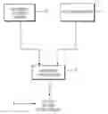
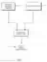
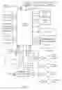
Sources:
- United States Patent and Trademark Office - verify current appl. status at the USPTO↗
Recent applications in this class:
- » 20230073939 2023-03-09
CALIBRATING AN IMAGE CAPTURE DEVICE WITH A DETACHABLE LENS - » 20220159187 2022-05-19
Actuator, image capturing unit and electronic device - » 20220070374 2022-03-03
Calibrating an image capture device with a detachable lens - » 20210385380 2021-12-09
Camera device having shiftable optical path - » 20210337121 2021-10-28
Multiple layer flexure for supporting a moving image sensor - » 20210281756 2021-09-09
Camera module and optical device including same - » 20210243372 2021-08-05
Imaging apparatus to which an interchangeable lens apparatus is attached that utilize image circle information of an imaging optical system in the interchangeable lens apparatus - » 20210227138 2021-07-22
Portable image pickup apparatus with carabiner structure - » 20200314338 2020-10-01
Multiple layer flexure for supporting a moving image sensor - » 20200275026 2020-08-27
Intelligent dual-lens photographing device and photographing method therefor
Recent applications for this Assignee:
- » 20100315516 2010-12-16
Camera unit incoporating program script scanner - » 20100214386 2010-08-26
Print engine assembly with dual motor assemblies - » 20100097480 2010-04-22
Camera system for with velocity sensor and de-blurring processor - » 20100045330 2010-02-25
Apparatus for testing integrated circuitry - » 20090303295 2009-12-10
Ink compartment refill unit with inlet valve acutator, outlet valve, actuator, and constrictor mechanism actuator - » 20090273645 2009-11-05
Inkjet printhead having proportional ejection ports and arms - » 20090237458 2009-09-24
Inkjet nozzle arrangement with rectangular plan nozzle chamber and ink ejection paddle - » 20090213155 2009-08-27
Printhead having sequenced nozzle firing on integrated circuit - » 20090195607 2009-08-06
Inkjet printhead nozzle arrangement with movement transfer mechanism - » 20090160909 2009-06-25
Inkjet printer nozzle arrangement having thermal actuator with inner and outer portion of inverse profile