Method for controlling attenuation of an optical element
US20060291081A1
2006-12-28
11/166,623
2005-06-23
✅ Patent granted
US 7,239,790 B2
2007-07-03
-
-
Sung Pak | Daniel Petkovsek
2025-11-25
Abstract:
A method for controlling the attenuation of an optical element. A base material, such as a resin, is selected from which to fabricate the optical element. The base material has an intrinsic attenuation or intrinsic absorption spectrum. A predetermined concentration of a first type of dye molecule is then added to the base material to vary the intrinsic attenuation of the base material to achieve a predetermined absorption spectrum.
Inventors:
- Eric Vancoille 6 🇸🇬 Singapore, Singapore
- Frank J. Flens 1 🇮🇹 Torino, Italy
- Frank J. Flens 1 🇮🇹 Turin, Italy
Assignee:
- AVAGO TECHNOLOGIES FIBER IP (SINGAPORE) PTE. LTD. 313 🇸🇬 SINGAPORE, Singapore
Interested in similar patents?
Get notified when new applications in this technology area are published.
Classification:
G02B5/223 » CPC main
Optical elements other than lenses; Filters; Absorbing filters containing organic substances, e.g. dyes, inks or pigments
G02B5/205 » CPC further
Optical elements other than lenses; Filters Neutral density filters
G02B5/22 IPC
Optical elements other than lenses; Filters Absorbing filters
G02B6/00 IPC
Light guides
G02B6/12 IPC
Light guides of the optical waveguide type of the integrated circuit kind
Description
BACKGROUND OF THE INVENTIONCommunicating information through light instead of electrical signals has many useful applications. The medium for light travel is typically a fiber optic cable. A transceiver circuit is typically coupled to each end of the fiber optic cable and includes an optical transmitter that performs transmission functions and an optical receiver that performs receiving functions. The transmitter includes a laser that acts as a source of light. An important component in the transceiver is an optical element that receives the light generated by the laser and launches the light into the fiber optic cable in a manner that minimizes reflections back to the laser and that provides favorable launch conditions to increase the bandwidth of the system. There are some situations in which it is desired to decrease the optical power of the laser signal.
There are several current prior art approaches to decrease the optical power of the laser signal. One approach to decrease the optical power of the laser signal is to apply partially reflective coatings on a surface of the optical element. Although these coatings provide tolerable control over the direction in which unwanted light is reflected, these coatings tend to be expensive. Furthermore, these coatings are prone to de-adhesion from the optical element, which can lead to undesirable results in the field.
Another approach to decrease the optical power of the laser signal is to machine or otherwise cause one surface of the optical element to become a textured surface. For example, surfaces of the optical element can be roughened surfaces. These textured surfaces act to scatter incoming light by re-distributing the light in a wide range of directions. It is noted that these textured surfaces do not absorb the incoming light. Unfortunately, the scattered light may cause interference or other problems with components adjacent to the optical element.
Yet another approach to utilize diffractive optical elements and partial beam blockers in the optical signal path between the laser and the fiber optic cable. Unfortunately, the diffractive optical elements and partial beam blockers tend to influence the optical signal's modal behavior. Consequently, these elements tend to complicate the design and placement of the laser, especially in terms of determining the appropriate launch intensity.
Based on the foregoing, there remains a need for a method and apparatus that controls the attenuation of an optical element that overcomes the disadvantages set forth previously.
SUMMARY OF THE INVENTIONAccording to one embodiment of the present invention, a method for controlling the attenuation of an optical element is described. A base material, such as a resin, is selected from which to fabricate the optical element. The base material has an intrinsic attenuation or intrinsic absorption spectrum. A predetermined concentration of a first type of dye molecule is then added to the base material to vary the intrinsic attenuation of the base material to achieve a predetermined absorption spectrum.
BRIEF DESCRIPTION OF THE DRAWINGSThe present invention is illustrated by way of example, and not by way of limitation, in the figures of the accompanying drawings and in which like reference numerals refer to similar elements.
FIG. 1 illustrates a system in which the optical element of the invention can be implemented.
FIG. 2 illustrates an exemplary attenuator optical element according to one embodiment of the invention.
FIG. 3 illustrates the physics of an absorber-attenuator according to one embodiment of the invention.
FIG. 4 is a flowchart illustrating the processing steps to manufacture the optical element according to one embodiment of the invention.
FIG. 5 illustrates an exemplary signal intensity versus length graph of an optical element according to one embodiment of the invention.
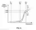
FIG. 6 illustrates an exemplary signal intensity versus wavelength graph of an optical element according to one embodiment of the invention.
DETAILED DESCRIPTIONA method for controlling attenuation of an optical element is described. In the following description, for the purposes of explanation, numerous specific details are set forth in order to provide a thorough understanding of the present invention. It will be apparent, however, to one skilled in the art that the present invention may be practiced without these specific details. In other instances, well-known structures and devices are shown in block diagram form in order to avoid unnecessarily obscuring the present invention.
System 100
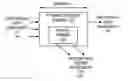
FIG. 1 illustrates a system 100 in which the optical element 110 of the invention can be implemented. The system 110 includes a light source 120 (e.g., a laser), an optical element 110, and optic fiber 130. Light, depicted as rays, is outputted by the laser 120 and provided to the optical element 110. The optical element 110 directs the light to the optic fiber 130 for transmission therein. The optical element 110 according to one embodiment of the invention is described in greater detail hereinafter with reference to FIGS. 2 and 3.
In one embodiment of the invention, the system 100 is a transmission module of a fiber optic transceiver. For example, the attenuator optical element 110 of the invention is utilized in a transmission path (e.g., as part of the transmitter module) in the fiber optics transceiver.
Attenuator 110
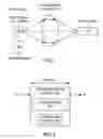
FIG. 2 illustrates an exemplary attenuator optical element 110 according to one embodiment of the invention. In one embodiment, the optical element 110 is implemented with a monolithic block of polymeric material 210 with a pre-determined length (L). The monolithic block of polymeric material includes an attenuator function 220 that ensures that the average light optical power at the outgoing or exit side (e.g., right side) is less than the average light optical power at the incoming side (e.g., left side).
In other words, an attenuator optical element receives an incoming optical signal with a first average optical power P1 and generates or provides an outgoing optical signal with a second average optical power P2. It is noted that the light path can extend along the entire length L of the optical element or can extend along a portion of the length of the optical element (e.g., partially through the length of the optical element).
According to one embodiment of the invention, an attenuator optical element is described. The attenuator optical element includes a base material, such as a resin. In one embodiment, the base material is polyetherimide that is about 98 wt % of the material. The base material has an intrinsic attenuation or intrinsic absorption spectrum. The attenuator optical element also includes a predetermined concentration of a first type of dye molecule that is added to the base material to vary the intrinsic attenuation of the base material to achieve a predetermined absorption spectrum. In one embodiment, the dye, which can include one or more different types of dye molecules, is less than about 2 wt % of the material.
Attenuator Physics
FIG. 3 illustrates the physics principle of an absorber-attenuator according to one embodiment of the invention. In one embodiment, the material of the attenuator optical element converts incoming radiation with an energy (hn1) into molecular lattice vibrations by utilizing one or more types of dye molecules. For example, the incoming photon (I1) is converted to a crystal phonon (i.e., a lattice vibration), which emits photons of a much larger wavelength (I2). In one embodiment, the dye molecules are homogenously distributed through the optical block of material. The use of dye molecules is described in greater detail hereinafter with reference to FIG. 4.
The molecular vibrations are eventually expressed to the outside of the optical element as a type of radiation (e.g., heat) with an energy much lower than the incident energy entering the optical element.
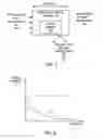
FIG. 5 illustrates an exemplary signal intensity versus length graph of an optical element according to one embodiment of the invention. The vertical axis represents signal intensity (T), and the horizontal axis represents the length of the optical element. As the length of the optical element (e.g., absorbing optical block) increases, the observed attenuated light intensity experiences an exponential drop or decrease. Consequently, this effect on signal intensity can be expressed in a decibel scale (e.g., a logarithmic scale) as a linear quantity that may be expressed as decibel per millimeter block length, for example. This quantity is also referred to herein as “intrinsic” attenuation of the block of polymer material. It is noted that the waveform that represents the optical signal decays over length as an exponential of the intrinsic attenuation multiplied by the length.
FIG. 6 illustrates an exemplary signal intensity versus wavelength graph of an optical element according to one embodiment of the invention. The vertical axis represents signal intensity (T) for a block optical element with constant length (L), and the horizontal axis represents the wavelength of incident radiation (P1). The vertical axis is also referred to as the transmitted optical power curve (P2) and represents the signal transmitted by the optical element. By selecting different dye molecules and by creating different resulting compositions according to the invention, the attenuation characteristics (e.g., absorbance versus wavelength spectrum) optical element may be tailored to meet the requirements of a specific application. For example, the composition of the optical element may be tailored for substantial suppression of the visible spectrum (e.g., in the range or about 400 nm to about 700 nm) and a predetermined level of transmission at a predetermined wavelength range (e.g., the range about the 850 nm region).
In this example, a first attenuation curve (A1) 610 and a second attenuation curve (A2) 620 are shown. Both curves 610 and 620 exhibit substantial attenuation in the range from about a first wavelength (W1) 650 to a second wavelength (W2)
660. At about a third wavelength (W3) 670, the first curve 610 has a first intensity value (T1) 630 and the second curve 620 has a second intensity value (T2) 640.
One or more different types of dye molecules can be added together to achieve substantial or complete light blockage at a predetermined range of wavelengths (e.g., visible wavelengths from W1 to W2) in a certain portion of the optical element. Also, one or more different types of dye molecules can be added together to achieve a controllable light intensity attenuation for one or more wavelengths (e.g., a second predetermined range of wavelengths) in a portion of the optical element. The correlation between the amount of dye molecules and the attenuation attained or achieved may be established and verified experimentally.
When the optical element is utilized in fiber optical transceiver applications that employ a broadband detection element (e.g., monitor-diode 140), substantially blocking the light at visible wavelengths is advantageous since scattered light from visible wavelengths may produce a false “received signal” at the detector.
It is noted that absorbing dyes can have an absorption peak or peaks with certain values, and at the same time the peaks each have a predetermined width. Both the height of the absorption peak and width of the peak are to be considered in selection of the dye-type and dye-concentration. The height and width of the peaks determine the absorption characteristics and range of the dye.
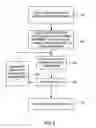
Processing to Control the Attenuation of an Optical ElementFIG. 4 is a flowchart illustrating a method for controlling the attenuation of an optical element according to one embodiment of the invention. In step 410, a host material, such as a base resin, is selected. The host material can include, but is not limited to, polyetherimides, polyimides, poly(phenyl)sulphones, plastics, and other polymeric materials. Preferably, for the fiber-optic transceiver application, the host material is a polymeric material that has a glass transition temperature in excess of temperatures common in the manufacture or processing of fiber-optic transceivers. These temperatures can exceed 200 degrees Celsius due to the manufacturing processes, such as board soldering. In one embodiment, the polymeric material is selected from thermoplasts that have a high molecular weight, that are aromatic, that are aliphatic, and that contain complex molecules.
Moreover, because fiber optic transceivers have an operating range of about −20 degrees Celsius to about 85 degrees Celsius at any humidity, in fiber optic transceiver applications, it is preferred that the polymeric material selected does not absorb water molecules above a predetermined limit or amount. Water molecules in the optical element increase the risk of crack formation in the optical element, which in turn may lead to failure of the lens.
In step 420, one or more different types of attenuator dyes are selected and then combined with the host material for form a composition. For example, the attenuator dye may be mixed, blended, or otherwise combined with the host material to form a composition for the optical element. In one embodiment, a single type of attenuator dye (e.g., molecules of a single type of dye) is combined with the host material to form a resulting composition. In another embodiment, a several different types of attenuator dye (e.g., molecules of four types of different dye) are combined with the host material to form a resulting composition.
The attenuator dye can include, but are not limited to, anthraquinone single dye, palladium dithiolene single dye, platinum dithiolene single dye, nickel dithiolene dye, phtalocyanine dye, azo dye, aromatic amines dye, methine dye, cyanine dye, and other types of dyes. Preferably, the dyes are resistant to high temperatures, such as the temperatures common to processing of optic transceivers and operation thereof as discussed previously.
In step 430, the attenuation characteristics of the composition is tested. This step can include the following sub-steps. For example, a test plate can be created (e.g., molded) from the composition. The test plate is then tested by determining the absorption spectrum of the test plate with light measurements and comparing the measured absorption spectrum with the predetermined design requirement (e.g., a predetermined specific absorption spectrum). When it is determined that the attenuation meets one or more predetermined requirements, a test lens is created. For example, a test lens may be molded and then subject to tests and corresponding measurements.
In step 440 a determination is made whether the attenuation of the composition fails to meets one or more predetermined requirements. When the attenuation characteristics of the composition do not meet the predetermined specific absorption spectrum, the dye recipe is modified and a new test plate is created, tested, etc. in step 460. For example, the dye recipe may be modified by adjusting the concentration of the dye molecules, by introducing new dye molecules into the composition or by deleting or omitting exiting dye molecules from the composition.
When it is determined that the attenuation meets the predetermined requirements, a final attenuator lens product is created in step 450. Otherwise, as noted previously with reference to step 440, when it is determined that the attenuation fails to meets one or more predetermined requirements, the dye recipe is modified in step 460, and the testing of step 430 is performed again. For example, the concentration of the dye may be modified or a different dye molecule may be selected. It is noted that one or more different dye molecules may be utilized to realize the absorbance versus wavelength characteristics or spectrum.
In one embodiment, the apparatus and method for controlling attenuation of an optical element according to one embodiment the invention can be implemented in a fiber optic transceiver. However, it is noted that the apparatus and method for controlling attenuation of an optical element according to one embodiment may be beneficial in any system in which there is a need to attenuate light power or there is a need to create a specific absorption spectrum.
One advantage of this approach is that the apparatus and method for controlling attenuation of an optical element according to one embodiment of the invention is manufacturable and may be mass-produced in a cost effective manner. Stated differently, by integrating the attenuation function into the optical element, the apparatus and method for controlling attenuation of an optical element avoids mechanical manipulation of a separate element that would require high manufacturing costs to align, etc.
Another advantage of this approach is that the apparatus and method for controlling attenuation of an optical element according to one embodiment of the invention enables a designer to customize and to meet different design requirements by varying factors, such as the concentration of the dye, combination of different dyes, and selection of different dyes, etc. These design requirements may vary due to different applications, different design requirements, different wavelength ranges, and different degrees of attenuation.
In the foregoing specification, the invention has been described with reference to specific embodiments thereof. It will, however, be evident that various modifications and changes may be made thereto without departing from the broader scope of the invention. The specification and drawings are, accordingly, to be regarded in an illustrative rather than a restrictive sense.
Claims
What is claimed is:1. A method of controlling attenuation in an optical element comprising:
fabricating a monolithic block of polymeric material with a predetermined length; wherein the monolithic block of polymeric material includes an integrated attenuator function that reduces the optical power received by the optical element; and
combining at least one type of dye to the polymeric material to implement the attenuator function.
2. The method of claim 1 adjusting the length of the monolithic block of polymeric material.
3. The method of claim 1 adjusting the concentration of the first dye molecules.
4. The method of claim 1 adding a first concentration of first type of attenuator block material.
5. The method of claim 1 wherein adding a first concentration of first type of attenuator block material includes adding a first concentration of cyanine dye.
6. The method of claim 5 further including adjusting the first concentration of the first type of attenuator block material to vary the intrinsic attenuation of the attenuator block.
7. The method of claim 1 adding a first concentration of second type of attenuator block material.
8. The method of claim 1 wherein adding a first concentration of second type of attenuator block material includes adding a first concentration of nickel dithiolene dye.
9. The method of claim 5 further including adjusting the first concentration of the second type of attenuator block material to vary the intrinsic attenuation of the attenuator block.
10. The method of claim 1 further including adding a first concentration of a first type of attenuator block material to fully absorb light having a first wavelength; and adding a first concentration of a second type of attenuator block material to partially absorb light having a second wavelength.
11. The method of claim 1 further including adding a first concentration of a first type of attenuator block material to fully absorb visible light; and adding a first concentration of a second type of attenuator block material to partially absorb light at a first predetermined wavelength and a second predetermined wavelength; wherein one of the first and second wavelengths is a wavelength of light generated by a laser source.
12. The method of claim 11 wherein adding a first concentration of a first type of attenuator block material to fully absorb visible light includes adding a first concentration of a first type of attenuator block material to fully absorb light that has a wavelength in the range of about 400 nm to about 700 nm; and wherein adding a first concentration of a second type of attenuator block material to partially absorb light at a first predetermined wavelength and a second predetermined wavelength includes adding a first concentration of a second type of attenuator block material to partially absorb light at about 850 nm and at about 1300 nm.
13. The method of claim 1 wherein fabricating a monolithic block of polymeric material includes fabricating a monolithic block of polyetherimide.
14. The method of claim 1 wherein combining at least one type of dye to the polymeric material to implement the attenuator function includes combining at least one type of dye to the polymeric material to achieve a predetermined absorption spectrum.
15. The method of claim 1 wherein combining at least one type of dye to the polymeric material includes adding one of cyanine dye that absorbs light in a first range of wavelengths, cyanine dye that absorbs light in a second range of wavelengths, nickel dithiolene dye that absorbs at a first maximum wavelength, nickel dithiolene dye that absorbs at a second maximum wavelength.
Images & Drawings included:
Sources:
- United States Patent and Trademark Office - verify current appl. status at the USPTO↗
Recent applications in this class:
- » 20250271605 2025-08-28
Light Control Film and Method of Fabricating Same - » 20250199218 2025-06-19
ELECTRONIC DEVICE - » 20250147211 2025-05-08
LAMINATE, MANUFACTURING METHOD OF LAMINATE, AND VIRTUAL REALITY DISPLAY APPARATUS - » 20250123432 2025-04-17
LIGHT ABSORPTION FILTER, OPTICAL FILTER, MANUFACTURING METHOD FOR OPTICAL FILTER, ORGANIC ELECTROLUMINESCENT DISPLAY DEVICE, INORGANIC ELECTROLUMINESCENT DISPLAY DEVICE, AND LIQUID CRYSTAL DISPLAY DEVICE - » 20250102714 2025-03-27
THIN FILM INTERFERENCE PIGMENTS WITH A COATING OF NANOPARTICLES - » 20250067915 2025-02-27
THIN FILM TYPE FILTER FOR ATTENUATING LIGHT AND METHOD OF PRODUCING THE SAME - » 20250035827 2025-01-30
WAVELENGTH SELECTIVE ABSORPTION FILTER AND ORGANIC ELECTROLUMINESCENT DISPLAY DEVICE - » 20240385357 2024-11-21
RGB-IRP FILM GROUP AND PREPARATION PROCESS THEREFOR - » 20240295682 2024-09-05
LIGHT ABSORPTION FILTER, OPTICAL FILTER, MANUFACTURING METHOD FOR OPTICAL FILTER, ORGANIC ELECTROLUMINESCENT DISPLAY DEVICE, INORGANIC ELECTROLUMINESCENT DISPLAY DEVICE, AND LIQUID CRYSTAL DISPLAY DEVICE - » 20240255683 2024-08-01
OPTICAL FILTER
Recent applications for this Assignee:
- » 20150192747 2015-07-09
Modified transistor outline (TO)-can assembly for use in optical communications and a method - » 20140064666 2014-03-06
Multi-optical fiber connector module having a cover comprising unfilled plastic having deformable features formed therein, and a method - » 20140056560 2014-02-27
Methods and systems for blind mating multi-optical fiber connector modules - » 20140037254 2014-02-06
Side-edge mountable parallel optical communications module, an optical communications system that incorporates the module, and a method - » 20140023312 2014-01-23
Optical cable plug-in detection - » 20140010552 2014-01-09
Z-pluggable optical communications module, an optical communications system, and a method - » 20140010546 2014-01-09
Method and apparatus for performing data rate conversion and phase alignment - » 20130322887 2013-12-05
Optical communications card, an optical communications system, and methods and apparatuses for providing high-density mounting of optical communications cards - » 20130300858 2013-11-14
Methods and systems for performing vision-aided passive alignment during the assembly of an optical communications module - » 20130287394 2013-10-31
High-speed optical fiber link and a method for communicating optical data signals