SYSTEM AND METHOD FOR USE IN VISUAL MODELING
US20060294497A1
2006-12-28
11/279,760
2006-04-14
Abstract:
A system and method for use in visual (e.g., UML) modeling are provided. According to one embodiment a method is disclosed which comprises providing a diagram of a model; defining predetermined focal points in the diagram; selecting one of the predetermined focal points and displaying the selected focal point at a scale to facilitate use of the displayed part of the model. In another embodiment the focal point is selected from a list of labels associated respectively with the predetermined focal points.
Interested in similar patents?
Get notified when new applications in this technology area are published.
Classification:
G06F8/10 » CPC main
Arrangements for software engineering Requirements analysis; Specification techniques
G06F9/44 IPC
Arrangements for program control, e.g. control units using stored programs, i.e. using an internal store of processing equipment to receive or retain programs Arrangements for executing specific programs
Description
CROSS-REFERENCE TO RELATED APPLICATIONSThe present application hereby claims benefit of priority to United Kingdom patent application number 0512668.5 entitled, “System and Method for Use in Visual Modelling,” filed on Jun. 22, 2005, naming G C Charters as inventor, assigned to the assignee of the present application, which is herein incorporated by reference in its entirety and for all purposes.
BACKGROUND1. Technical Field
This invention relates to development and maintenance of systems such as software applications utilizing visual development environments such as Unified Modeling Language (UML) layout.
2. Description of the Related Art
UML is a standard graphical language for modeling complex object-oriented systems. Further information on UML is available at Internet website www.uml.org. UML, at its simplest, is a language that graphically describes a set of elements. At its most complex, UML may used to model (e.g., specify, visualize, construct, and document) not only software systems but also business models and non-software systems. UML provides a graphical representation of a system design that may be used by developers to assure architectural soundness of a system. UML is frequently used to design the relationships between components (e.g., classes in the case of a Java program) before such components are developed and implemented in source code format.
Large diagrams for models (e.g., those created in UML modeling tools such as “Rational Rose”—an object-oriented UML software design tool intended for visual modeling and component construction of enterprise-level software applications) are difficult for a user to navigate in practice because the whole model at once cannot meaningfully be displayed on the user's screen. A user typically has to rely on remembering the diagram's layout and then using scroll bars to navigate to the place of interest. Diagrams can be split into sub-diagrams, but many people prefer to describe the model as a whole. There are a number of solutions to navigating large diagrams such as zooming in and out, but these are generic in use and bear no relevance to the information in the model being navigated.
Thus, modeling tools for designing/diagramming suffer the drawback that they usually need to display a large number of model elements (such as boxes) on screen, which elements may include additional data (annotations, characteristics, etc.) which it may also be desirable to view. Navigation of such large models can be arduous using horizontal and vertical scroll bars and zoom settings, and identifying an appropriate set of elements to be viewed on screen together at an appropriate level of zoom can be time-consuming.
A need therefore exists for a scheme for use in visual modeling wherein the above mentioned disadvantage(s) may be alleviated.
SUMMARYA system and method for use in visual (e.g., UML) modeling are provided. In one embodiment, a method is disclosed which comprises providing a diagram of a model; defining predetermined focal points in the diagram; selecting one of the predetermined focal points; and displaying the selected focal point at a scale to facilitate use of the displayed part of the model. In another embodiment the focal point is selected from a list of labels associated respectively with the predetermined focal points.
BRIEF DESCRIPTION OF THE DRAWING(S)One system and method for use in visual modeling incorporating the present invention will now be described, by way of example only, with reference to the accompanying drawing(s), in which:
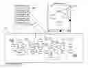
FIG. 1 shows a schematic illustration of a UML diagram and ‘focused’ utilization thereof following the present invention.
DETAILED DESCRIPTIONReferring now to FIG. 1, a complete diagram 100 of a software system modeled in UML comprises a large number of elements (such as software modules 110.01 . . . 100.30) connected as depicted by arrows. The size of the complete diagram 100 is far greater than can be useably displayed in the viewable screen area, since the large size of the diagram renders impractical its display as a whole on a user's display screen (not shown) at a magnification or scale to allow its easy use by the user. Heretofore, in order to display the diagram at a useful magnification the user would have to decide on a less-than-entire portion of the diagram for display and would then have to zoom the display to a satisfactory magnification and scroll the display (e.g., using horizontal and vertical scroll bars) in well-known manner so as to center the display at a desired position. This combination of zooming and scrolling is time-consuming and cumbersome.
In order to facilitate use of the UML diagram 100, a number of ‘focal points’ (depicted as X) in the diagram are defined, each focal point being a key point of interest in the complete diagram. In the diagram 100, four focal points (fp1, fp2, fp3, fp4) are illustrated.
The focal points can be selected by a user and the model will then be displayed with respect to the selected focal point. The focal points can be defined (e.g., by the user) in terms of a center of gravity of a number of model elements, or the focal point can be automatically defined by the system based on the relative positions of particular types of model elements. A center of gravity of a number of model elements in a set of model elements is a point which represents the set of model elements by its particular position. For example, the position of a center of gravity of a number of model elements can be a point which is equidistant from each of the model elements. Alternatively, the position of a center of gravity can be the center of a polygon formed by lines drawn between each of the model elements.
The model/diagram creator can annotate focal points in the model, by associating a label (in the diagram illustrated as “focal point 1”, “focal point 2”, “focal point 3” and “focal point 4”) with a focal point. A focal point label may thus be considered as identifying the center of a key point of interest in the diagram. The focal points may then be listed (such as in list 200) on the user's display screen, and when selected from the list (e.g., when, as illustrated, “focal point 2” is selected by positioning a cursor and clicking with a mouse—not shown—or via a keyboard—also not shown) the user's UML system would navigate directly to and display that point and its immediate surroundings in the diagram as visible area 300 on the user's display screen at a suitably high magnification to facilitate the user to view and work with the relevant elements of the UML model.
A number of ways are envisaged for capturing focal points and updating them as the model evolves. For example, a focal point could be defined as the center of gravity of a number of model artifacts; as these artifacts are moved or deleted, the focal point is recalculated. Alternatively, a focal point could be initially created as a discrete point in the model, but then have its nearest model artifacts calculated and its position preserved relative to those as the model is changed. A focal point could also be automatically determined from artifact classifications. For example, a model of software components might have those components classified into packages. These packages could be used to automatically define focal points in diagrams including those artifacts.
Thus, in a different context of a corporate data model defining entities pertaining to customers, orders and employees, the ability to label focal points in terms of the model would allow focal points to be labeled for example as “customers”, “orders” and “employees”.
It will be appreciated that the ‘focal point’ scheme described above is carried out in software running on a processor in one or more computers, and that the software may be provided as a computer program element carried on any suitable data carrier (not shown) such as a magnetic or optical computer disc.
In conclusion it will be understood that the system and method for use in visual modeling described above provides the advantages of allowing easy display and use of points (and surrounding areas) of interest in a complete diagram.
Claims
1. A system for use in visual modeling, the system comprising:
means for providing a diagram of a model;
means for defining at least one predetermined focal point in the diagram; and
means for selecting the at least one predetermined focal point and for displaying the at least one predetermined focal point at a scale to facilitate use of a displayed part of the model.
2. The system according to claim 1, wherein the means for selecting comprises means for displaying a list of labels, for user selection therefrom, associated respectively with a plurality of focal points including the at least one predetermined focal point.
3. The system according to claim 1, wherein the means for defining comprises means for defining the at least one predetermined focal point as substantially a center of gravity of a plurality of artifacts of the model.
4. The system according to claim 3 wherein the means for defining comprises means for recalculating the at least one predetermined focal point based upon a modification of at least one of the plurality of artifacts.
5. The system according to claim 1 wherein the means for defining comprises means for initially defining a discrete focal point in the model, and means for calculating at least one nearest model artifact and preserving a position of the discrete focal point relative to the at least one nearest model artifact as the model is changed.
6. The system according to claim 1 wherein the means for defining comprises means for automatically determining the at least one predetermined focal point from artifact classifications of the model.
7. The system according to claim 1 wherein the model comprises a Unified Modeling Language model.
8. A method for use in visual modeling, the method comprising:
providing a diagram of a model;
defining at least one predetermined focal point in the diagram; and
selecting the at least one predetermined focal point and displaying the at least one predetermined focal point at a scale to facilitate use of a displayed part of the model.
9. The method according to claim 8, wherein the step of selecting comprises displaying a list of labels, for user selection therefrom, associated respectively with a plurality of focal points including the at least one predetermined focal point.
10. The method according to claim 8, wherein the defining comprises defining the at least one predetermined focal point as substantially a center of gravity of a plurality of artifacts of the model.
11. The method according to claim 10 wherein the defining comprises recalculating the at least one predetermined focal point based upon a modification of at least one of the plurality of artifacts.
12. The method according to claim 8 wherein the defining comprises initially defining a discrete focal point in the model, and calculating at least one nearest model artifact and preserving a position of the discrete focal point relative to the at least one nearest model artifact as the model is changed.
13. The method according to claim 8 wherein the defining comprises automatically determining the at least one predetermined focal point from artifact classifications of the model.
14. The method according to claim 8 wherein the model comprises a Unified Modeling Language model.
15. A computer program element stored on a data carrier and comprising computer program means, which when executed by a computer, cause the computer to perform a method for use in visual modeling the method comprising:
providing a diagram of a model;
defining at least one predetermined focal point in the diagram; and
selecting the at least one predetermined focal point and displaying the at least one predetermined focal point at a scale to facilitate use of a displayed part of the model.
16-17. (canceled)
Images & Drawings included:
Sources:
- United States Patent and Trademark Office - verify current appl. status at the USPTO↗
Similar patent applications:
- » 20250094482
METHOD AND SYSTEM FOR IMAGE CATEGORIZATION USING A VISUAL LANGUAGE MODEL - » 20190212898
System and method for visualization of history of events using BIM model - » 20160306523
System and method for visualization of history of events using BIM model - » 20060041539
Method and apparatus for organizing, visualizing and using measured or modeled system statistics - » 20250139950
System and Method of Visual Attribute Recognition Using a Deep Learning Model - » 20150043887
System and method for visualization of history of events using BIM model - » 20100041369
System and method of using diameter based signaling to support billing models for visually rendered services - » 20210343014
Systems, methods, and apparatuses for the use of transferable visual words for AI models through self-supervised learning in the absence of manual labeling for the processing of medical imaging - » 20210256406
System and Method Associated with Generating an Interactive Visualization of Structural Causal Models Used in Analytics of Data Associated with Static or Temporal Phenomena - » 20200409665
Systems and methods for seamlessly integrating multiple products by using a common visual modeler
Recent applications in this class:
- » 20250165222 2025-05-22
COMPUTER PROGRAM SPECIFICATION BUILDER - » 20250156153 2025-05-15
AUTOMATED ENHANCEMENTS AND ANALYTICS FOR COMPUTER PROGRAM DEVELOPMENT - » 20250117190 2025-04-10
INTEGRATION FLOW DESIGN GUIDELINES VALIDATOR - » 20250094131 2025-03-20
IDENTIFYING ARTIFICIAL INTELLIGENCE FOR INFORMATION TECHNOLOGY OPERATIONS SOLUTION FOR RESOLVING ISSUES - » 20250077187 2025-03-06
GENERATING SOFTWARE ARCHITECTURE FROM CONVERSATION - » 20250060942 2025-02-20
GENERATING IDEATION SCENARIOS BASED ON INTENTS ASSOCIATED WITH REQUIREMENTS - » 20250028506 2025-01-23
INFORMATION PROCESSING DEVICE, INFORMATION PROCESSING METHOD, AND PROGRAM - » 20240402998 2024-12-05
STABLE POINT DETERMINATION FOR MONITORING USER MOVEMENTS - » 20240378023 2024-11-14
METHOD FOR QUALITY ASSURANCE OF A SYSTEM - » 20240354062 2024-10-24
METHOD AND SYSTEM FOR GENERATING AUTOMATION DOMAIN OBJECTS USING KNOWLEDGE FROM ANOTHER AUTOMATION DOMAIN OBJECT