Red phosphorescence compounds
US20070004918A1
2007-01-04
11/518,162
2006-09-11
✅ Patent granted
US 7,470,928 B2
2008-12-30
-
-
Rei-tsang Shiao | Joseph R Kosack
2026-09-11
Abstract:
Red phosphorescene compounds and organic electro-luminescence device using the same are disclosed. In an organic electroluminescence device including an anode, a hole injecting layer, a hole transport layer, a light emitting layer, an electron transport layer, an electron injecting layer, and a cathode serially deposited on one another, the organic electroluminescence device may use a compound as a dopant of the light emitting layer.
Inventors:
- Jae-Man Lee 22 🇰🇷 Seoul, South Korea
- Kyung-Hoon LEE 76 🇰🇷 Seoul, South Korea
- Jung Keun KIM 32 🇰🇷 Seoul, South Korea
- Chun-Gun Park 30 🇰🇷 Seoul, South Korea
- Hyun Cheol Jeong 14 🇰🇷 Jinju-si, South Korea
- Jeong Dae Seo 2 🇰🇷 Ycounsu-gu, South Korea
- Jeong Dae Seo 5 🇰🇷 Inchon, South Korea
Assignee:
- LG ELECTRONICS INC. 44,418 🇰🇷 Seoul, South Korea
Interested in similar patents?
Get notified when new applications in this technology area are published.
Classification:
C07F15/0033 » CPC main
Compounds containing elements of Groups 8, 9, 10 or 18 of the Periodic System compounds of the platinum group Iridium compounds
C09K11/06 » CPC further
Luminescent, e.g. electroluminescent, chemiluminescent materials containing organic luminescent materials
H01L51/0085 » CPC further
Solid state devices using organic materials as the active part, or using a combination of organic materials with other materials as the active part; Processes or apparatus specially adapted for the manufacture or treatment of such devices, or of parts thereof; Selection of organic semiconducting materials, e.g. organic light sensitive or organic light emitting materials; Coordination compounds, e.g. porphyrin; Transition metal complexes, e.g. Ru(II)polypyridine complexes comprising Iridium
H05B33/14 » CPC further
Electroluminescent light sources; Light sources with substantially two-dimensional radiating surfaces characterised by the chemical or physical composition or the arrangement of the electroluminescent material, or by the simultaneous addition of the electroluminescent material in or onto the light source
C09K2211/1007 » CPC further
Chemical nature of organic luminescent or tenebrescent compounds; Non-macromolecular compounds; Carbocyclic compounds Non-condensed systems
C09K2211/1029 » CPC further
Chemical nature of organic luminescent or tenebrescent compounds; Non-macromolecular compounds; Heterocyclic compounds characterised by ligands containing one nitrogen atom as the heteroatom
C09K2211/1092 » CPC further
Chemical nature of organic luminescent or tenebrescent compounds; Non-macromolecular compounds; Heterocyclic compounds characterised by ligands containing sulfur as the only heteroatom
C09K2211/185 » CPC further
Chemical nature of organic luminescent or tenebrescent compounds; Metal complexes of the platinum group, i.e. Os, Ir, Pt, Ru, Rh or Pd
C09K2211/186 » CPC further
Chemical nature of organic luminescent or tenebrescent compounds; Metal complexes of the light metals other than alkali metals and alkaline earth metals, i.e. Be, Al or Mg
C09K2211/188 » CPC further
Chemical nature of organic luminescent or tenebrescent compounds; Metal complexes of other metals not provided for in one of the previous groups
H01L51/0052 » CPC further
Solid state devices using organic materials as the active part, or using a combination of organic materials with other materials as the active part; Processes or apparatus specially adapted for the manufacture or treatment of such devices, or of parts thereof; Selection of organic semiconducting materials, e.g. organic light sensitive or organic light emitting materials; Macromolecular systems with low molecular weight, e.g. cyanine dyes, coumarine dyes, tetrathiafulvalene Polycyclic condensed aromatic hydrocarbons, e.g. anthracene
H01L51/0059 » CPC further
Solid state devices using organic materials as the active part, or using a combination of organic materials with other materials as the active part; Processes or apparatus specially adapted for the manufacture or treatment of such devices, or of parts thereof; Selection of organic semiconducting materials, e.g. organic light sensitive or organic light emitting materials; Macromolecular systems with low molecular weight, e.g. cyanine dyes, coumarine dyes, tetrathiafulvalene Amine compounds having at least two aryl rest on at least one amine-nitrogen atom, e.g. triphenylamine
H01L51/0062 » CPC further
Solid state devices using organic materials as the active part, or using a combination of organic materials with other materials as the active part; Processes or apparatus specially adapted for the manufacture or treatment of such devices, or of parts thereof; Selection of organic semiconducting materials, e.g. organic light sensitive or organic light emitting materials; Macromolecular systems with low molecular weight, e.g. cyanine dyes, coumarine dyes, tetrathiafulvalene aromatic compounds comprising a hetero atom, e.g.: N,P,S
H01L51/0078 » CPC further
Solid state devices using organic materials as the active part, or using a combination of organic materials with other materials as the active part; Processes or apparatus specially adapted for the manufacture or treatment of such devices, or of parts thereof; Selection of organic semiconducting materials, e.g. organic light sensitive or organic light emitting materials; Coordination compounds, e.g. porphyrin Phthalocyanine
H01L51/0081 » CPC further
Solid state devices using organic materials as the active part, or using a combination of organic materials with other materials as the active part; Processes or apparatus specially adapted for the manufacture or treatment of such devices, or of parts thereof; Selection of organic semiconducting materials, e.g. organic light sensitive or organic light emitting materials; Coordination compounds, e.g. porphyrin; Metal complexes comprising a IIIB-metal (B, Al, Ga, In or TI), e.g. Tris (8-hydroxyquinoline) gallium (Gaq3) comprising aluminium, e.g. Alq3
H01L51/5016 » CPC further
Solid state devices using organic materials as the active part, or using a combination of organic materials with other materials as the active part; Processes or apparatus specially adapted for the manufacture or treatment of such devices, or of parts thereof specially adapted for light emission, e.g. organic light emitting diodes [OLED] or polymer light emitting devices [PLED]; Electroluminescent [EL] layer Triplet emission
Y10S428/917 » CPC further
Stock material or miscellaneous articles Electroluminescent
C07F15/00 IPC
Compounds containing elements of Groups 8, 9, 10 or 18 of the Periodic System
C07D215/00 IPC
Heterocyclic compounds containing quinoline or hydrogenated quinoline ring systems
Description
CROSS-REFERENCE TO RELATED APPLICATIONSThis is a Divisional Application of prior application Ser. No. 11/128,421 filed May 13, 2005 whose entire disclosure is incorporated herein by reference. Further, this application claims the benefit of the Patent Korean Application No. 10-2005-0019182, filed on Mar. 8, 2005, which is hereby incorporated by reference as if fully set forth herein.
BACKGROUND OF THE INVENTION1. Field of the Invention
The present invention relates to an organic electroluminescence device, and more particularly, to red phosphorescene compounds and organic electroluminescence device using the same. Most particularly, the present invention relates to red phosphorescence being used as a dopant of a light emitting layer of an organic electroluminescence device, which is formed by serially depositing an anode, a hole injecting layer, a hole transport layer, a light emitting layer, an electron transport layer, an electron injecting layer, and a cathode.
2. Discussion of the Related Art
Recently, as the size of display devices is becoming larger, the request for flat display devices that occupy lesser space is becoming more in demand. Such flat display devices include organic electroluminescence devices, which are also referred to as an organic light emitting diode (OLED). Technology of such organic electroluminescence devices is being developed at a vast rate and various prototypes have already been disclosed.
The organic electroluminescence device emits light when electric charge is injected into an organic layer, which is formed between an electron injecting electrode (cathode) and a hole injecting electrode (anode). More specifically, light is emitted when an electron and a hole form a pair and the newly created electron-hole pair decays. The organic electroluminescence device can be formed on a flexible transparent substrate such as plastic. The organic electro-luminescence device can also be driven under a voltage lower than the voltage required in a plasma display panel or an inorganic electroluminescence (EL) display (i.e., a voltage lower than or equal to 10V). The organic electroluminescence device is advantageous in that it consumes less energy as compared to other display devices and that it provides excellent color representation. Moreover, since the organic EL device can reproduce pictures by using three colors (i.e., green, blue, and red), the organic EL device is widely acknowledged as a next generation color display device that can reproduce vivid images.
The process of fabricating such organic electroluminescence (EL) device will be described as follows:
- (1) An anode material is coated over a transparent substrate. Generally, indium tin oxide (ITO) is used as the anode material.
- (2) A hole injecting layer (HIL) is deposited on the anode material. The hole injecting layer is formed of a copper phthalocyanine (CuPc) layer having a thickness of 10 nanometers (nm) to 30 nanometers (nm).
- (3) A hole transport layer (HTL) is then deposited. The hole transport layer is mostly formed of 4,4′-bis[N-(1-naphtyl)-N-phenylamino]-biphenyl (NPB), which is treated with vacuum evaporation and then coated to have a thickness of 30 nanometers (nm) to 60 nanometers (nm).
- (4) Thereafter, an organic light emitting layer is formed. At this point, a dopant may be added if required. In case of green emission, the organic light emitting layer is generally formed of tris(8-hydroxy-quinolate)aluminum (Alq3) which is vacuum evaporated to have a thickness of 30 nanometers (nm) to 60 nanometers (nm). And, MQD(N-Methylquinacridone) is used as the dopant (or impurity).
- (5) Either an electron transport layer (ETL) and an electron injecting layer (EIL) are sequentially formed on the organic emitting layer, or an electron injecting/transport layer is formed on the organic light emitting layer. In case of green emission, the Alq3 of step (4) has excellent electron transport ability. Therefore, the electron injecting and transport layers are not necessarily required.
- (6) Finally, a layer cathode is coated, and a protective layer is coated over the entire structure.
A light emitting device emitting (or representing) the colors of blue, green, and red, respectively, is decided in accordance with the method of forming the light emitting layer in the above-described structure. As the light emitting material, an exciton is formed by a recombination of an electron and a hole, which are injected from each of the electrodes. A singlet exciton emits fluorescent light, and a triplet exciton emits phosphorescene light. The singlet exciton emitting fluorescent light has a 25% probability of formation, whereas the triplet exciton emitting phosphorescene light has a 75% probability of formation. Therefore, the triplet exciton provides greater light emitting efficiency as compared to the singlet exciton. Among such phosphorescene materials, red phosphorescence material may have greater light emitting efficiency than fluorescent materials. And so, the red phosphorescene material is being researched and studied as an important factor for enhancing the efficiency of the organic electroluminescence device.
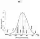
When using such phosphorescene materials, high light emitting efficiency, high color purity, and extended durability are required. Most particularly, when using red phosphorescene materials, the visibility decreases as the color purity increases (i.e., the X value of the CIE chromacity coordinates becomes larger), thereby causing difficulty in providing high light emitting efficiency. Accordingly, red phosphorescence material that can provide characteristics of excellent chromacity coordinates (CIE color purity of X=0.65 or more), enhanced light emitting efficiency, and extended durability needs to be developed.
SUMMARY OF THE INVENTIONAccordingly, the present invention is directed to red phosphorescence compounds and an organic electro-luminescence device using the same that substantially obviate one or more problems due to limitations and disadvantages of the related art.
An object of the present invention is to provide an organic electroluminescence device having high color purity, high brightness, and long durability by combining the compound shown in Formula 1, which is used as a dopant in a light emitting layer of the organic EL device.
Additional advantages, objects, and features of the invention will be set forth in part in the description which follows and in part will become apparent to those having ordinary skill in the art upon examination of the following or may be learned from practice of the invention. The objectives and other advantages of the invention may be realized and attained by the structure particularly pointed out in the written description and claims hereof as well as the appended drawings.
To achieve these objects and other advantages and in accordance with the purpose of the invention, as embodied and broadly described herein, a red phosphorescence compound is indicated as Formula 1 below:
Herein each of R1, R2, R3, and R4 may be one of substituted or non-substituted C1 to C6 alkyl groups with disregard of one another. And, each of the C1 to c6 alkyl groups may be selected from a group consisting of methyl, ethyl, n-propyl, i-propyl, n-butyl, i-butyl, and t-butyl.
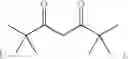
Additionally,
may include 2,4-pentanedione
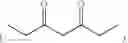
2,2,6,6,-tetra-methylheptane-3,5-dione
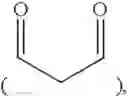
1,3-propanedione
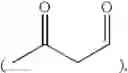
1,3-butanedione
3,5-heptanedione
1,1,1-trifluoro-2,4-pentanedione
1,1,1,5,5,5-hexafluoro-2,4-pentanedione
and 2,2-dimethyl-3,5-hexanedione
Moveover,
may be any one of the following chemical formulas:
Furthermore, the Formula 1 may be any one of the following chemical formulas:
In another aspect of the present invention, in an organic electroluminescence device including an anode, a hole injecting layer, a hole transport layer, a light emitting layer, an electron transport layer, an electron injecting layer, and a cathode serially deposited on one another, the organic electroluminescence device may use any one of the above-described formulas as a dopant of the light emitting layer.
Herein, any one of Al and Zn metallic complexes and a carbazole derivative may be used as a host of the light emitting layer, and usage of the dopant may be within the range of 0.1 wt.% to 50 wt. %. The efficiency of the present invention may be provided when the amount of dopant used is within the above-described range. Furthermore, a ligand of each of the Al and Zn metallic complexes may include quinolyl, biphenyl, isoquinolyl, phenyl, methylquinolyl, dimethyl-quinolyl, dimethyl-isoquinolyl, and wherein the carbazole derivative may include CBP.
It is to be understood that both the foregoing general description and the following detailed description of the present invention are exemplary and explanatory and are intended to provide further explanation of the invention as claimed.
BRIEF DESCRIPTION OF THE DRAWINGSThe accompanying drawings, which are included to provide a further understanding of the invention and are incorporated in and constitute a part of this application, illustrate embodiments of the invention and together with the description serve to explain the principle of the invention. In the drawings:
FIG. 1 illustrates a graph showing a decrease in visibility as color purity of an organic EL device increases (i.e., as the X value of chromacity coordinates becomes greater); and
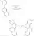
FIG. 2 illustrates structural formula of NPB, copper (II) phthalocyanine (CuPc), (bpt)2Ir(acac), Alq3, BAlq, and CBP, which are compounds used in embodiments of the present invention.
DETAILED DESCRIPTION OF THE INVENTIONReference will now be made in detail to the preferred embodiments of the present invention, examples of which are illustrated in the accompanying drawings. Wherever possible, the same reference numbers will be used throughout the drawings to refer to the same or like parts.
A method of combining the red phosphorescence compound according to the present invention will now be described. An iridium (III)(2-(3-methylphenyl)-7-methyl-quinolinato-N, C2)(2,4-pentanedionate-0,0) compound, which is shown as A-2 among the red phosphorescene compounds used in the organic EL device according to the present invention.
COMBINATION EXAMPLE1. Combination of 2-(3-methylphenyl)-7-methyl-quinoline
3-methyl-phenyl-boric acid (1.3 mmol), 2-chloro-7-methyl-quinoline (1 mmol), tetrakis (triphenyl phosphine) palladium(0) (0.05 mmol), and potassium carbonate (3 mmol) are dissolved in a two-neck round bottom flask containing THF (30 ml) and H2O (10 ml). The mixture is then stirred for 24 hours in a bath of 100 degrees Celsius (° C.). Subsequently, when reaction no longer occurs, the THF and toluene are discarded. The mixture is extracted by using dichloromethane and water, which is then treated with vacuum distillation. Then, after filtering the mixture with a silica gel column, a solvent is treated with vacuum distillation. Thereafter, by using dichloromethane and petroleum ether, the mixture is re-crystallized and filtered, thereby yielding solid 2-(3-methylphenyl)-7-methyl-quinoline.
2. Formation of chloro-cross-linked dimer Complex
Iridium chloride (1 mmol) and 2-(3-methylphenyl)-7-methyl-quinoline (2.5 mmol) are mixed in a 3:1 liquid mixture (30 ml) of 2-ethoxyethanol and distilled water. Then, the mixture is refluxed for 24 hours. Thereafter, water is added so as to filter the solid form that is produced. Subsequently, the solid form is washed by using methanol and petroleum ether, thereby yielding the chloro-cross-linked dimer complex.
3. Formation of iridium (III)(2-(3-methylphenyl)-7-methyl-quinolinato-N, C2)(2,4-pentanedionate-0,0)
A chloro-cross-linked dimer complex (1 mmol), 2,4-pentane dione (3 mmol), and Na2CO3 (6 mmol) are mixed into 2-ethoxyethanol (30 ml) and refluxed for 24 hours. The refluxed mixture is then cooled at room temperature. Thereafter, distilled water is added to the cooled mixture, which is filtered so as to yield a solid form. Subsequently, the solid form is dissolved in dichloromethane, which is then filtered by using silica gel. Afterwards, the dichloromethane is treated with vacuum suction, and the solid form is washed by using methanol and petroleum ether, so as to obtain the chemical compound.
Hereinafter, examples of preferred embodiments will be given to describe the present invention. It will be apparent that the present invention is not limited only to the proposed embodiments.
Embodiments 1. First EmbodimentAn ITO glass substrate is patterned to have a light emitting area of 3 mm×3 mm. Then, the patterned ITO glass substrate is washed. Subsequently, the substrate is mounted on a vacuum chamber. The standard pressure is set to 1×10⁻⁶ torr. Thereafter, layers of organic matter are formed on the ITO substrate in the order of CuPC (200 Å), NPB (400 Å), CBP+(btp)2Ir(acac)(7%) (200 Å), a hole blocking layer (100 Å), Alq3 (300 Å), LiF (5 Å), and Al (1000 Å).
When forming a hole blocking layer using BAlq, the brightness is equal to 689 cd/m2 (8.1 V) at 0.9 mA. At this point, CIE x=0.651, y=0.329. Furthermore, the durability (half of the initial brightness) lasts for 1600 hours at 2000 cd/m2.
2. Second EmbodimentAn ITO glass substrate is patterned to have a light emitting area of 3 mm×3 mm. Then, the patterned ITO glass substrate is washed. Subsequently, the substrate is mounted on a vacuum chamber. The standard pressure is set to 1×10⁻⁶ torr. Thereafter, layers of organic matter are formed on the ITO substrate in the order of CuPC (200 Å), NPB (400 Å), BAlq+A-2(7%) (200 Å), Alq3 (300 Å), LiF (5 Å), and Al (1000 Å).
At 0.9 mA, the brightness is equal to 1448 cd/m2 (6.2 V). At this point, CIE x=0.644, y=0.353. Furthermore, the durability (half of the initial brightness) lasts for 8000 hours at 2000 cd/m2.
3. Third EmbodimentAn ITO glass substrate is patterned to have a light emitting area of 3 mm×3 mm. Then, the patterned ITO glass substrate is washed. Subsequently, the substrate is mounted on a vacuum chamber. The standard pressure is set to 1×10⁻⁶ torr. Thereafter, layers of organic matter are formed on the ITO substrate in the order of CuPC (200 Å), NPB (400 Å), BAlq+A-5(7%) (200 Å), Alq3 (300 Å), LiF (5 Å), and Al (1000 Å).
At 0.9 mA, the brightness is equal to 1378 cd/m2 (6.0 V). At this point, CIE x=0.659, y=0.351. Furthermore, the durability (half of the initial brightness) lasts for 7000 hours at 2000 cd/m2.
COMPARISON EXAMPLEAn ITO glass substrate is patterned to have a light emitting area of 3 mm×3 mm. Then, the patterned ITO glass substrate is washed. Subsequently, the substrate is mounted on a vacuum chamber. The standard pressure is set to 1×10⁻⁶ torr. Thereafter, layers of organic matter are formed on the ITO substrate in the order of CuPC (200 Å), NPB (400 Å), BAlq+(btp)2Ir(acac)(7%) (200 Å), Alq3 (300 Å), LiF (5 Å), and Al (1000 Å).
At 0.9 mA, the brightness is equal to 780 cd/m2 (7.5 V). At this point, CIE x=0.659, y=0.329. Furthermore, the durability (half of the initial brightness) lasts for 2500 hours at 2000 cd/m2.
In accordance with the above-described embodiments and comparison example, the characteristics of efficiency, chromacity coordinates, brightness, and durability are shown in Table 1 below.
| TABLE 1 | ||||||||
| Durability(h) | ||||||||
| Current | Power | ½ of | ||||||
| Voltage | Current | Brightness | Efficiency | Efficiency | CIE | CIE | initial | |
| Device | (V) | (mA) | (cd/m2) | (cd/A) | (1 m/W) | (X) | (Y) | brightness |
| First | 8.1 | 0.9 | 690 | 6.9 | 2.7 | 0.651 | 0.329 | 1600 |
| Embodiment | ||||||||
| Second | 6.2 | 0.9 | 1450 | 14.5 | 7.3 | 0.644 | 0.353 | 8000 |
| Embodiment | ||||||||
| Third | 6.0 | 0.9 | 1378 | 13.8 | 7.2 | 0.659 | 0.351 | 7000 |
| Embodiment | ||||||||
| Comparison | 7.5 | 0.9 | 780 | 7.8 | 3.3 | 0.659 | 0.329 | 2500 |
| Example | ||||||||
As shown in Table 1, the device is operated with high efficiency at a low voltage even when the color purity is high. Furthermore, the current efficiency of the second embodiment has increased by 100% or more as compared to the comparison example. Additionally, the durability of the second embodiment has increased to three times that of the comparison example.
Table 2 below shows the characteristics of efficiency, chromacity coordinates, and brightness in accordance with the increase in voltage and electric current in the organic electroluminescence device according to the second embodiment of the present invention.
| TABLE 2 | ||||||
| Current | Power | |||||
| Voltage | Current | Brightness | Efficiency | Efficiency | CIE | CIE |
| (V) | (A(mA/cm2) | (cd/m2) | (cd/A) | (1 m/W) | (X) | (Y) |
| 5.0 | 1.111 | 168.6 | 15.2 | 9.5 | 0.645 | 0.353 |
| 5.5 | 3.333 | 500.8 | 15.0 | 8.5 | 0.645 | 0.353 |
| 6.0 | 7.777 | 1139 | 14.6 | 7.6 | 0.644 | 0.354 |
| 6.5 | 16.666 | 2309 | 13.9 | 6.6 | 0.643 | 0.354 |
| 7.0 | 33.333 | 4275 | 12.9 | 5.7 | 0.643 | 0.355 |
| 7.5 | 66.666 | 7664 | 11.5 | 4.8 | 0.641 | 0.356 |
As shown in Table 2, the second embodiment provides excellent efficiency, and the chromacity coordinates according to the driving voltage also maintains high color purity.
It will be apparent to those skilled in the art that various modifications and variations can be made in the present invention without departing from the spirit or scope of the inventions. Thus, it is intended that the present invention covers the modifications and variations of this invention provided they come within the scope of the appended claims and their equivalents.
Claims
What is claimed is:1. A red phosphorescence compound being indicated as Formula 1 below:
wherein each of R1, R2, R3, and R4 is independently selected from the group consisting of hydrogen and substituted or non-substituted C1 to C6 alkyl groups, and
wherein
represents an alkanedione selected from the group consisting of 2,4-pentanedione, 2,2,6,6,-tetra-methylheptane-3,5-dione, 1,3-propanedione, 1,3-butanedione, 3,5-heptanedione, 1,1,1-trifluoro-2,4-pentanedione, 1,1,1,5,5,5-hexafluoro-2,4-pentanedione, and 2,2-dimethyl-3,5-hexanedione.
2. The red phosphorescence compound of claim 1, wherein each of the C1 to C6 alkyl groups is selected from a group consisting of methyl, ethyl, n-propyl, i-propyl, n-butyl, i-butyl, and t-butyl.
3. The red phosphorescence compound of claim 1, wherein
is any one of the following chemical formulas:
4. The red phosphorescence compound of claim 1, wherein the Formula 1 is any one of the following chemical formulas:
Images & Drawings included:


Sources:
- United States Patent and Trademark Office - verify current appl. status at the USPTO↗
Similar patent applications:
- » 20140175401
RED PHOSPHORESCENT COMPOUND AND ORGANIC LIGHT EMITTING DIODE DEVICE USING THE SAME - » 20060204785
Red phosphorescence compounds and organic electroluminescence device using the same - » 20070104979
Red phosphorescent compound and organic electroluminescent device using the same - » 20070104980
Red phosphorescent compounds and organic electroluminescent devices using the same - » 20070128468
Red phosphorescent compounds and organic electroluminescent devices using the same - » 20070224450
Red phosphorescent compound and organic electroluminescent device using the same - » 20090085476
Red phosphorescent compound and organic electroluminescent device using the same - » 20090104472
Red phosphorescent compounds and organic electroluminescent devices using the same - » 20060202194
Organic electroluminescence devices using red phosphorescence compounds - » 20140175402
Red phosphorescent compound and organic light emitting diode device using the same
Recent applications in this class:
- » 20250289838 2025-09-18
ORGANIC ELECTROLUMINESCENT MATERIALS AND DEVICES - » 20250282805 2025-09-11
ORGANOMETALLIC COMPOUND, LIGHT-EMITTING DEVICE INCLUDING THE SAME, AND ELECTRONIC APPARATUS INCLUDING THE LIGHT-EMITTING DEVICE - » 20250270244 2025-08-28
ORGANOMETALLIC COMPLEX, LIGHT-EMITTING MATERIAL FOR TOP EMISSION, LIGHT-EMITTING DEVICE, LIGHT-EMITTING APPARATUS, ELECTRONIC DEVICE, AND LIGHTING DEVICE - » 20250270243 2025-08-28
ORGANIC ELECTROLUMINESCENT MATERIALS AND DEVICES - » 20250263429 2025-08-21
ORGANIC ELECTROLUMINESCENT MATERIALS AND DEVICES - » 20250257087 2025-08-14
ORGANIC ELECTROLUMINESCENT MATERIALS AND DEVICES - » 20250243229 2025-07-31
ORGANIC ELECTROLUMINESCENT MATERIALS AND DEVICES - » 20250223309 2025-07-10
ORGANIC ELECTROLUMINESCENT MATERIALS AND DEVICES - » 20250215034 2025-07-03
ORGANOMETALLIC COMPOUND, ORGANIC LIGHT-EMITTING DEVICE INCLUDING THE SAME, AND ELECTRONIC APPARATUS INCLUDING THE ORGANIC LIGHT-EMITTING DEVICE - » 20250215033 2025-07-03
ORGANIC ELECTROLUMINESCENT MATERIALS AND DEVICES
Recent applications for this Assignee:
- » 20250294563 2025-09-18
METHOD AND DEVICE FOR INCREASING UPLINK CONTROL RESOURCES IN WIRELESS COMMUNICATION SYSTEM - » 20250294548 2025-09-18
METHOD AND DEVICE FOR TRANSMITTING/RECEIVING SIGNAL IN WIRELESS COMMUNICATION SYSTEM - » 20250294465 2025-09-18
METHOD AND APPARATUS FOR PERFORMING UPLINK TRANSMISSION IN WIRELESS COMMUNICATION SYSTEM - » 20250294425 2025-09-18
METHOD AND APPARATUS FOR MOBILITY BASED ON HEIGHT IN A WIRELESS COMMUNICATION SYSTEM - » 20250294206 2025-09-18
DISPLAY DEVICE AND CONTENT SHARING METHOD FOR SHARING CONTENT WITH EXTERNAL DISPLAY DEVICE - » 20250294153 2025-09-18
METHOD FOR CODING IMAGE ON BASIS OF SELECTIVE TRANSFORM AND DEVICE THEREFOR - » 20250294150 2025-09-18
METHOD AND APPARATUS FOR CABAC-BASED ENTROPY CODING - » 20250294136 2025-09-18
AFFINE MOTION PREDICTION-BASED IMAGE DECODING METHOD AND APPARATUS USING AFFINE MVP CANDIDATE LIST IN IMAGE CODING SYSTEM - » 20250292745 2025-09-18
SINK DEVICE AND OPERATING METHOD THEREOF - » 20250291418 2025-09-18
ELECTRONIC DEVICE HAVING TOUCH PAD REGION AND KEYBOARD