Supporting device for supporting an article thereon
US20070007409A1
2007-01-11
11/300,434
2005-12-15
✅ Patent granted
US 7,441,739 B2
2008-10-28
-
-
Amy J. Sterling | Tan Le
2026-08-17
Abstract:
A supporting device includes: a first part that is formed with upper and lower retaining grooves; a second part that is formed with an upper hook extending into the upper retaining groove in such a manner that the second part is pivotable relative to the first part between first and second positions, the second part being further formed with a lower hook that is disposed in the lower retaining groove when the second part is disposed at the first position, and that is disposed outwardly of the lower retaining groove when the second part is disposed at the second position; and a locking member mounted movably in the lower retaining groove and engageable releasably with the lower hook when the lower hook is disposed in the lower retaining groove.
Inventors:
- Ming-Hsien Huang 1 🇹🇼 Hsi-Chih City, Taiwan
- Ming-Hsien Huang 3 🇹🇼 Hsi-Chih City, Taipei Hsien, Taiwan
Interested in similar patents?
Get notified when new applications in this technology area are published.
Classification:
E04G3/00 IPC
Scaffolds essentially supported by building constructions, e.g. adjustable in height
F16M13/02 » CPC main
Other supports for positioning apparatus or articles ; Means for steadying hand-held apparatus or articles for supporting on, or attaching to, an object, e.g. tree, gate, window-frame, cycle
F16M11/10 » CPC further
Stands or trestles as supports for apparatus or articles placed thereon Stands for scientific apparatus such as gravitational force meters; Heads; Means for attachment of apparatus; Means allowing adjustment of the apparatus relatively to the stand allowing pivoting around a horizontal axis
F16B2/12 » CPC further
Friction-grip releasable fastenings; Clamps, i.e. with gripping action effected by positive means other than the inherent resistance to deformation of the material of the fastening external, i.e. with contracting action using sliding jaws
F16B5/065 » CPC further
Joining sheets or plates, e.g. panels, to one another or to strips or bars parallel to them by means of clamps or clips joining sheets or plates to each other in parallel relationship the plates being one on top of the other and distanced from each other, e.g. by using protrusions to keep contact and distance
F16B5/0664 » CPC further
Joining sheets or plates, e.g. panels, to one another or to strips or bars parallel to them by means of clamps or clips joining sheets or plates to each other in parallel relationship at least one of the sheets or plates having integrally formed or integrally connected snap-in-features
F16B5/07 » CPC further
Joining sheets or plates, e.g. panels, to one another or to strips or bars parallel to them by means of multiple interengaging protrusions on the surfaces, e.g. hooks, coils
Y10S248/917 » CPC further
Supports Video display screen support
E04G5/06 IPC
Component parts or accessories for scaffolds Consoles; Brackets
B42F13/00 IPC
Filing appliances with means for engaging perforations or slots
Description
CROSS-REFERENCE TO RELATED APPLICATIONThis application claims priority of Taiwanese application no. 093139161, filed on Dec. 16, 2004.
BACKGROUND OF THE INVENTION1. Field of the Invention
This invention relates to a supporting device for supporting an article thereon, more particularly to a supporting device having a first part formed with upper and lower retaining grooves, and a second part formed with upper and lower hooks that are respectively engageable with the upper and lower retaining grooves.
2. Description of the Related Art
Conventionally, a display device is supported on a supporting device, such as a stand or a frame, such that the display device is firmly held on the supporting device and cannot rotate relative to the supporting device. However, in some occasions, the display device is required to be tilted to a certain angle relative to the supporting device so that connection or disconnection between a cable line and a connector on the display device can be easily performed.
SUMMARY OF THE INVENTIONTherefore, the object of the present invention is to provide a supporting device that is capable of overcoming the aforesaid drawback of the prior art.
According the present invention, there is provided a supporting device that comprises: a first part that is formed with upper and lower retaining grooves; a second part that is adapted to support the article and that is formed with an upper hook extending into the upper retaining groove in such a manner that the second part is pivotable relative to the first part between first and second positions, the second part being further formed with a lower hook that is disposed in the lower retaining groove when the second part is disposed at the first position, and that is disposed outwardly of the lower retaining groove when the second part is disposed at the second position; and a locking member mounted movably in the lower retaining groove and engageable releasably with the lower hook when the lower hook is disposed in the lower retaining groove, thereby retaining the second part at the first position.
BRIEF DESCRIPTION OF THE DRAWINGSIn drawings which illustrate embodiments of the invention,
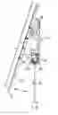
FIG. 1 is an exploded perspective view of the first preferred embodiment of a supporting device according to this invention;
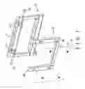
FIG. 2 is an exploded perspective view of the second preferred embodiment of the supporting device according to this invention;
FIG. 3 is an assembled sectional view illustrating a state where a lower hook of the second preferred embodiment is disposed outwardly of a lower retaining groove;
FIG. 4 is an assembled sectional view illustrating another state where the lower hook of the second preferred embodiment is disposed in the lower retaining groove;
FIG. 5 is an exploded perspective view of the third preferred embodiment of the supporting device according to this invention;
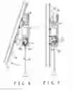
FIG. 6 is an assembled sectional view illustrating a state where a lower hook of the third preferred embodiment is disposed outwardly of a lower retaining groove; and
FIG. 7 is an assembled sectional view illustrating another state where the lower hook of the third preferred embodiment is disposed in the lower retaining groove.
DETAILED DESCRIPTION OF THE PREFERRED EMBODIMENTSBefore the present invention is described in greater detail with reference to the accompanying preferred embodiments, it should be noted herein that like elements are denoted by the same reference numerals throughout the disclosure.
FIG. 1 illustrates the first preferred embodiment of a supporting device according to the present invention for supporting an article 24, such as a display, thereon.
The supporting device of this embodiment includes a first part 3 adapted to be fixed to a wall (not shown), and a second part 5 pivoted to the first part 3 and adapted to support the article 24 through protrusions 25 which protrude from the article 24. The first part 3 includes a generally rectangular frame 11 that is formed with a pair of pivot protrusions 110. The second part 5 includes a U-shaped frame 20 that has two opposite ends 201 which are respectively pivoted to the pivot protrusions 110 through a pair of pivot pins 23 so as to permit pivoting movement of the second part 5 together with the article 24 relative to the first part 3.
FIGS. 2 to 4 illustrate the second preferred embodiment of the supporting device according to this invention.
The supporting device of this embodiment includes: a first part 3 that is formed with upper and lower retaining grooves 300, 312; a second part 5 that is adapted to support the article (not shown) and that is formed with a pair of upper hooks 50 extending into the upper retaining groove 300 in such a manner that the second part 5 is pivotable relative to the first part 3 between first and second positions, the second part 5 being further formed with a pair of lower hooks 51 that are disposed in the lower retaining groove 312 when the second part 3 is disposed at the first position (see FIG. 4), and that are disposed outwardly of the lower retaining groove 312 when the second part 5 is disposed at the second position (see FIG. 3); and a locking member 4 mounted movably in the lower retaining groove 312 and engageable releasably with the lower hooks 51 when the lower hooks 51 are disposed in the lower retaining groove 312, thereby retaining the second part 5 at the first position.
In this embodiment, the locking member 4 includes a generally L-shaped plate 41 having a hook end 412 and movable between an upper position (see FIG. 4), in which the hook end 412 engages the lower hooks 51 when the second part 5 is disposed at the first position, and a lower position (see FIG. 3), in which the hook end 412 disengages the lower hooks 51.
The locking member 4 further includes a pair of urging members 421 mounted in the lower retaining groove 312 underneath the L-shaped plate 41 for urging the L-shaped plate 41 to the upper position. An operating member 42 includes a thin rod 420 connected to the L-shaped plate 41, and is operable to move the L-shaped plate 41 against urging action of the urging members 421 from the upper position to the lower position. A pair of protective sleeves 43 are sleeved on two ends of the L-shaped plate 41.
The first part 3 includes a first portion 31 that has a generally C-shaped cross-section and that defines the lower retaining groove 312, and a second portion 32 that has a generally J-shaped cross-section and that defines the upper retaining groove 300. The second part 5 includes a central plate body 52 and a U-shaped frame body 53 around the central plate body 52 and integrally connected to the central plate body 52. The upper and lower hooks 50, 51 are formed on the U-shaped frame body 53. The central plate body 52 is adapted to be connected to the article (not shown).
FIGS. 5 to 7 illustrate the third preferred embodiment of the supporting device according to this invention. The supporting device of this embodiment differs from the second preferred embodiment in that the second part 5 includes a pair of separate vertical plates, each of which has a generally Z-shaped cross-section and each of which has a first portion 54, a second portion 55 parallel to the first portion 54, and an intermediate portion that interconnects an adjacent pair of ends of the first and second portions 54, 55. The upper and lower hooks 50, 51 are formed on the first portions 54 of the vertical plates of the second part 5. The second portions 55 of the vertical plates of the second part 5 are adapted to be connected to the article (not shown).
With the inclusion of the upper and lower retaining grooves 300, 312 and the upper and lower hooks 50, 51 in the supporting device of this invention, the aforesaid drawback associated with the prior art can be eliminated.
With the invention thus explained, it is apparent that various modifications and variations can be made without departing from the spirit of the present invention.
Claims
What is claimed is:1. A supporting device for supporting an article thereon, comprising:
a first part that is formed with upper and lower retaining grooves;
a second part that is adapted to support the article and that is formed with an upper hook extending into said upper retaining groove in such a manner that said second part is pivotable relative to said first part between first and second positions, said second part being further formed with a lower hook that is disposed in said lower retaining groove when said second part is disposed at said first position, and that is disposed outwardly of said lower retaining groove when said second part is disposed at said second position; and
a locking member mounted movably in said lower retaining groove and engageable releasably with said lower hook when said lower hook is disposed in said lower retaining groove, thereby retaining said second part at said first position.
2. The supporting device of claim 1, wherein said locking member includes a generally L-shaped plate having a hook end and movable between an upper position, in which said hook end engages said lower hook when said second part is disposed at said first position, and a lower position, in which said hook end disengages said lower hook.
3. The supporting device of claim 2, wherein said locking member further includes a pair of urging members mounted in said lower retaining groove underneath said L-shaped plate for urging said L-shaped plate to said upper position.
4. The supporting device of claim 3, further comprising an operating member that is connected to said L-shaped plate and that is operable to move said L-shaped plate against urging action of said urging members from said upper position to said lower position.
Images & Drawings included:


Sources:
- United States Patent and Trademark Office - verify current appl. status at the USPTO↗
Recent applications in this class:
- » 20250290597 2025-09-18
WALL MOUNTED EQUIPMENT SUPPORT - » 20250290596 2025-09-18
FLOATING MOVING OBJECT AND PROBE MECHANISM - » 20250277558 2025-09-04
BRACKET, SYSTEM AND METHOD FOR HANGING ARTICLES UNDER A STRUCTURE - » 20250271099 2025-08-28
POULTRY FEEDER AND WATERER WITH HANDLE AND SUPPORT PROVIDING AN ADJUSTABLE HEIGHT - » 20250271098 2025-08-28
GRAB BAR ASSEMBLY - » 20250264188 2025-08-21
SEISMIC BRACING YIELD FUSE - » 20250264187 2025-08-21
STAND FOR DISPLAY APPARATUS AND DISPLAY APPARATUS INCLUDING SAME - » 20250243972 2025-07-31
SELF-INSERTING TREE HANGER - » 20250243971 2025-07-31
Mounting system for a tablet - » 20250243970 2025-07-31
RAIL SUPPORTING APPARATUS FOR SUPPORTING TUBULAR RAIL MEMBER FOR BOARDING SPORTS ON A BASE FRAME