Method of image joining for scanner
US20070007433A1
2007-01-11
11/267,251
2005-11-07
✅ Patent granted
US 8,619,344 B2
2013-12-31
-
-
Fred Guillermety
Perkins Coie LLP
2033-06-15
Abstract:
An image joining method for a scanner that scans and transfers image data to a terminal is provided. During scanning and data transfer, when the image data stored in a register is full, an image processor stops the scanning of a linear photodetector. Meanwhile, a matrix photodetector fetches and stores the image of a code strip. Then, the photodetectors are moved backward a distance larger than that being required to be accelerated forward when the scanner resumes scanning. After the data in the register being transferred and cleared, the linear photodetector resumes scanning at a normal moving speed. The code strip image is further fetched and compared with the stored one to get a joining point of scanned image data. By the joining point, the new and prior image data portions are joined and the scanning proceeds, and joined image data will not be overlapped or broken.
Assignee:
- Muller Capital, LLC 3 🇺🇸 Wilmington, DE, United States
Applicant:
Interested in similar patents?
Get notified when new applications in this technology area are published.
Classification:
H04N1/0473 » CPC main
Scanning, transmission or reproduction of documents or the like, e.g. facsimile transmission; Details thereof; Scanning arrangements, i.e. arrangements for the displacement of active reading or reproducing elements relative to the original or reproducing medium, or; Detection, control or error compensation of scanning velocity or position in subscanning direction, e.g. picture start or line-to-line synchronisation
H04N1/32358 » CPC further
Scanning, transmission or reproduction of documents or the like, e.g. facsimile transmission; Details thereof; Circuits or arrangements for control or supervision between transmitter and receiver or between image input and image output device, e.g. between a still-image camera and its memory or between a still-image camera and a printer device using picture signal storage, e.g. at transmitter
H04N1/32448 » CPC further
Scanning, transmission or reproduction of documents or the like, e.g. facsimile transmission; Details thereof; Circuits or arrangements for control or supervision between transmitter and receiver or between image input and image output device, e.g. between a still-image camera and its memory or between a still-image camera and a printer device using picture signal storage, e.g. at transmitter with asynchronous operation of the image input and output devices connected to the memory Controlling data flow to or from the memory in relation to the available memory capacity
H04N1/1013 » CPC further
Scanning, transmission or reproduction of documents or the like, e.g. facsimile transmission; Details thereof; Scanning arrangements, i.e. arrangements for the displacement of active reading or reproducing elements relative to the original or reproducing medium, or using flat picture-bearing surfaces with sub-scanning by translatory movement of at least a part of the main-scanning components
H04N1/193 » CPC further
Scanning, transmission or reproduction of documents or the like, e.g. facsimile transmission; Details thereof; Scanning arrangements, i.e. arrangements for the displacement of active reading or reproducing elements relative to the original or reproducing medium, or using multi-element arrays the array comprising a one-dimensional array, or a combination of one-dimensional arrays, or a substantially one-dimensional array, e.g. an array of staggered elements; Simultaneously or substantially simultaneously scanning picture elements on one main scanning line using electrically scanned linear arrays, e.g. linear CCD arrays
H04N2201/04712 » CPC further
Indexing scheme relating to scanning, transmission or reproduction of documents or the like, and to details thereof; Scanning arrangements; Detection, control or error compensation of scanning velocity or position; Detection of scanning velocity or position using dedicated detectors using unbroken arrays of detectors, i.e. detectors mounted on the same substrate
H04N2201/0472 » CPC further
Indexing scheme relating to scanning, transmission or reproduction of documents or the like, and to details thereof; Scanning arrangements; Detection, control or error compensation of scanning velocity or position; Detection of scanning velocity or position by detecting marks or the like, e.g. slits on or adjacent the sheet support
H04N2201/04734 » CPC further
Indexing scheme relating to scanning, transmission or reproduction of documents or the like, and to details thereof; Scanning arrangements; Detection, control or error compensation of scanning velocity or position; Detection of scanning velocity or position Detecting at frequent intervals, e.g. once per line for sub-scan control
H04N2201/3294 » CPC further
Indexing scheme relating to scanning, transmission or reproduction of documents or the like, and to details thereof; Circuits or arrangements for control or supervision between transmitter and receiver or between image input and image output device, e.g. between a still-image camera and its memory or between a still-image camera and a printer device using picture signal storage, e.g. at transmitter; Storage of less than a complete document page or image frame of several complete lines, e.g. a band of data
H04N2201/04755 » CPC further
Indexing scheme relating to scanning, transmission or reproduction of documents or the like, and to details thereof; Scanning arrangements; Detection, control or error compensation of scanning velocity or position; Control or error compensation of scanning position or velocity by controlling the position or movement of a scanning element or carriage, e.g. of a polygonal mirror, of a drive motor
H04N2201/04787 » CPC further
Indexing scheme relating to scanning, transmission or reproduction of documents or the like, and to details thereof; Scanning arrangements; Detection, control or error compensation of scanning velocity or position; Control or error compensation of scanning position or velocity by controlling the position of the scanned image area by changing or controlling the addresses or values of pixels, e.g. in an array, in a memory, by interpolation
H01L27/00 IPC
Devices consisting of a plurality of semiconductor or other solid-state components formed in or on a common substrate
H04N1/00 IPC
Scanning, transmission or reproduction of documents or the like, e.g. facsimile transmission; Details thereof
H04N1/36 IPC
Scanning, transmission or reproduction of documents or the like, e.g. facsimile transmission; Details thereof; Circuits or arrangements for control or supervision between transmitter and receiver or between image input and image output device, e.g. between a still-image camera and its memory or between a still-image camera and a printer device for synchronising or phasing transmitter and receiver
H04N1/40 IPC
Scanning, transmission or reproduction of documents or the like, e.g. facsimile transmission; Details thereof Picture signal circuits
H04N1/04 IPC
Scanning, transmission or reproduction of documents or the like, e.g. facsimile transmission; Details thereof Scanning arrangements, i.e. arrangements for the displacement of active reading or reproducing elements relative to the original or reproducing medium, or
Description
CROSS-REFERENCE TO RELATED APPLICATIONSThis non-provisional application claims priority under 35 U.S.C. § 119(a) on Patent Application No(s). 94123293 filed in Taiwan on Jul. 8, 2005, the entire contents of which are hereby incorporated by reference.
BACKGROUND OF THE INVENTION1. Field of Invention
The invention generally relates to a method of joining image, and in particular relates to a method applied in a scanner for joining the image data of a scanned document when the data in a register is full and the scanning is paused and resumed, the joining is prevented from being overlapped or broken.
2. Related Art
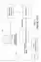
FIG. 1 is a schematic diagram of a conventional scanning device including a scanner 10 and a computer terminal 105. When scanning a document (not shown) being illuminated, a linear photodetector 101 gets scanning image signals of the document and transfers to an image processor 102. The image processor 102 converts the signals into digital signals (data) and stores into a register 103. With a protocol between a data-transfer interface 104 and the terminal 105, the image data is transferred from the register 103 to the terminal 105 and displayed.
However, since the transfer speed of image data from the image processor 102 to the register 103 is usually faster than that from the register 103 to the terminal 105, the image data stored in the register 103 is gradually full during the transfer. At a critical point, the image processor 102 has to stop a motor M1 and to stop the scanning of the linear photodetector 101. The motor M1 decelerates to stop the linear photodetector 101 so that the image data stored in the register 103 gets time to be transferred. After then, the motor M1 restarts to speed up the scanning of the linear photodetector 101 till a normal speed. After the pause and resuming, the broken image data portions have to be joined.
Since the motor M1 requires an acceleration time when restarting from still to a normal scanning speed, the linear photodetector 101 is first moved backward before restarting forward so as to resume scanning speed before reaching the position where it stopped scanning last time. By controlling the time of data acquiring when moving backward and forward, the scanning image data is supposed to be suitably joined.
However, caused by mechanical transmission deviation such as backlash of gears, the motor M1 and related transmission elements (not shown) usually make the scanning image data overlapped or broken after the backward and forward movements.
Therefore, there has been a scanning method that scans and stores image data during the backward movement. Then, compare the backward image data with the scanning image data when starting forward so as to get the matched portions for joining.
Still unfortunately, the aforesaid method fails when the scanning image data includes repeating portions.
SUMMARY OF THE INVENTIONThe object of the invention is to provide a method applied in a scanner for joining the image data of a scanned document in which the joining is prevented from being overlapped or broken.
An image joining method according to the invention is applicable to a scanner that scans and transfers image data to a computer terminal. The method includes the following steps.
During scanning and data transfer, when the image data stored in the register is full, an image processor stops the scanning. A motor decelerates to stop a scanning photodetector.
At the stop position, another photodetector fetches and stores the image of a code strip. Then, the scanning photodetector is moved backward a distance larger than that being required to be accelerated forward when the scanner resumes scanning. After the data in the register being transferred and cleared, the motor restarts to speed up the scanning photodetector till a normal speed and to resume scanning. In a time period, the code strip image is further fetched and compared with the stored code strip image so as to get a joining point of the scanned image data. By the correct joining point, the new and prior image data portions are joined and the scanning proceeds.
Therefore, the invention controls a matrix photodetector to fetch the image of a code strip and utilizes the code strip images to find out the correct joining point of scanned image data. The method prevents the joined image data from being overlapped or broken.
BRIEF DESCRIPTION OF THE DRAWINGSThe present invention will become more fully understood from the detailed description given hereinbelow illustration only, and thus are not limitative of the present invention, and wherein:
FIG. 1 is a schematic diagram of a conventional scanning device;
FIG. 2 is a schematic diagram of a scanning device applying the method of the invention;
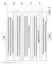
FIG. 3 is a flowchart of the method of the invention; and
FIG. 4 is an explanatory view of a scanning device applying the method of the invention.
DETAILED DESCRIPTION OF THE INVENTIONAs shown in FIG. 4, a scanner applying the method of the invention for joining image data of a scanned document 40 is equipped with a code strip 30. Further referring to FIG. 2, a scanning device applying the method of the invention includes a scanner 20 and a terminal 205 for receiving image data from the scanner. The scanner 20 includes photodetectors 201, an image processor 202, a data register 203 and a data transfer interface 204.
The photodetectors 201 further includes a linear photodetector 2011 and a matrix photodetector 2012. The linear photodetector 2011 is used to detect the image data of the document 40. The matrix photodetector 2012 is used to detect the image of the code strip 30 mounted on the scanner 20 so as to determine the positions of scanning stop and resuming. The linear photodetector 2011 and the matrix photodetector 2012 are both driven by a motor M2.
The image processor 202 receives analog signals of the scanned image from the linear photodetector 2011 and the code strip image from the matrix photodetector 2012 and converts into digital signal to be stored into the data register 203 and further transferred to the terminal 205 via the data transfer interface 204.
During scanning and data transfer, when the image data stored in the data register 203 is full, the image processor 202 stops the scanning. The motor M2 decelerates to stop the linear photodetector 2011. At the stop position, the matrix photodetector 2012 fetches and stores the image of the code strip 30. Then, the linear photodetector 2011 is moved backward a distance larger than that being required to be accelerated forward when the scanner resumes scanning. After the data in the register 203 being transferred and cleared, the motor M2 restarts to speed up the linear photodetector 2011 till a normal speed and to resume scanning. In a time period, the image of code strip 30 is further fetched and compared with the stored code image so as to get a joining point of scanned image data. By the correct joining point, the new and the prior image data portions are joined and the scanning proceeds.
Of course, the aforesaid stop and resuming process is repeated when the data register 203 being full again.
FIG. 2 is a schematic diagram of a scanning device applying the method of the invention. FIG. 3 is a flowchart of the method of the invention. FIG. 4 is an explanatory view of a scanning device applying the method of the invention. The image joining method of the invention includes the following steps.
In step 101, the image processor stops the motor and the linear photodetector and pauses scanning when the image processor detects the data register being full. Meanwhile, the image processor controls the matrix photodetector to fetch the image of a code strip when the linear photodetector stops.
In step 102, the photodetectors are moved backward by the motor a distance larger than that of acceleration from still to normal scanning speed.
In step 103, the data in the register has been cleared; the photodetectors are accelerated to start scanning, and the image of the code strip is fetched in a time period. The process is started by detection of the image processor that the register is cleared. Then, the image processor starts the motor to drive the linear photodetector accelerated to the scanning speed and obtaining scanned image. Meanwhile, the matrix photodetector fetches the code strip image.
In step 104, the image processor compares the code strip images being taken at the stop and being taken at the startup so as to get a joining point of the scanned image data.
In step 105, the scanned image data portions taken at the stop and taken at the startup are joined at the joining point, and the scanning proceeds till another pause or final finishing of the scan.
Therefore, the invention utilizes the matrix photodetector to fetch images of the code strip and refers to get a joining point of scanned image portions. The invention thus solves the problems of conventional scanning devices that cause overlapped or broken image data by mechanical deviation such as backlash of gears in motor and transmission elements. The method of the invention also prevents from the drawback of another prior art that simply compares backward and forward image portions and fails correct joining when encountering repeating image portions.
The invention being thus described, it will be obvious that the same may be varied in many ways. Such variations are not to be regarded as a departure from the spirit and scope of the invention, and all such modifications as would be obvious to one skilled in the art are intended to be included within the scope of the following claims.
Claims
What is claimed is:1. An image joining method, applicable to a scanner that scans and transfers scanned image data to a terminal via a register, comprising steps of:
decelerating a first photodetector to stop scanning when scanned image data stored in said register is full, and fetching and storing image of a code strip by a second photodetector;
moving backward said first and said second photodetectors a distance larger than that being required to be accelerated forward when the scanner resumes scanning;
accelerating said first photodetector till a normal speed and resuming scanning after said data in said register being transferred and cleared, and fetching said code strip image in a time period;
comparing said code strip image with said stored code strip image to get a joining point of scanned image data; and
joining said scanned image data at said joining point, and proceeding scanning until it ends up.
2. The image joining method of claim 1, wherein said step of decelerating a first photodetector to stop scanning when scanned image data stored in said register is full, and fetching and storing image of a code strip by a second photodetector is controlled by an image processor of said scanner that detects said register condition.
3. The image joining method of claim 1, wherein said step of decelerating a first photodetector to stop scanning when scanned image data stored in said register is full, and fetching and storing image of a code strip by a second photodetector is controlled by an image processor of said scanner that stops a motor to decelerate said first photodetector and to stop scanning.
4. The image joining method of claim 1, wherein said step of decelerating a first photodetector to stop scanning when scanned image data stored in said register is full, and fetching and storing image of a code strip by a second photodetector is controlled by an image processor of said scanner that turns on a matrix photodetector to fetch code strip image when scanning stops.
5. The image joining method of claim 1, wherein said step of moving backward said first and said second photodetectors a distance larger than that being required to be accelerated forward when the scanner resumes scanning is achieved by a motor that drives said photodetectors.
6. The image joining method of claim 1, wherein said step of accelerating said first photodetector till a normal speed and resuming scanning after said data in said register being transferred and cleared, and fetching said code strip image in a time period is controlled by an image processor of said scanner that detects said register condition and turns on a motor that drives said photodetectors.
7. The image joining method of claim 1, wherein said step of accelerating said first photodetector till a normal speed and resuming scanning after said data in said register being transferred and cleared, and fetching said code strip image in a time period is achieved by a linear photodetector that fetches said scanned image data, and a matrix photodetector that fetches said code strip image.
8. The image joining method of claim 1, wherein said step of comparing said code strip image with said stored code strip image to get a joining point of scanned image data is executed by an image processor.
Images & Drawings included:


Sources:
- United States Patent and Trademark Office - verify current appl. status at the USPTO↗
Recent applications in this class:
- » 20250267229 2025-08-21
IMAGE READING DEVICE AND IMAGE FORMING APPARATUS - » 20250159091 2025-05-15
IMAGE READING DEVICE, IMAGE READING METHOD, AND NON-TRANSITORY RECORDING MEDIUM - » 20240364828 2024-10-31
IMAGE FORMING SYSTEM INCLUDING IMAGE READING DEVICE - » 20230216970 2023-07-06
Image processing apparatus, control method thereof, image reading apparatus, and storage medium that shift inclined panels based on pixel inclination information and differentiating edge pixels from other parts of a scanned line - » 20220116509 2022-04-14
IMAGE READING APPARATUS FOR DETECTING END PORTION OF FRONT END OR REAR END OF MEDIUM - » 20220086300 2022-03-17
Image reading device comprising an outer peripheral member including two reference surfaces adjacent in the sub-scanning direction and differing in light reflectance - » 20200036853 2020-01-30
Image forming apparatus and operation method of image forming apparatus - » 20190222710 2019-07-18
Image scanner - » 20190116285 2019-04-18
Image reading apparatus - » 20190058809 2019-02-21
Document reading apparatus that reads document images of documents by image sensors
Recent applications for this Assignee:
- » 20110032584 2011-02-10
Scanning apparatus for transparent documents - » 20080063297 2008-03-13
Apparatus for eliminating moire in scanned image and method for the same