Drilling template
US20070009335A1
2007-01-11
11/178,253
2005-07-09
Abstract:
An apparatus is used to drill holes in the top area of the door on the hinge side of the door to install a door closer. The apparatus includes a template body that is installed over the top of the door with drill bushing to drill in door to install a door closer and a swivel compression clamp to hold the template in position while drilling the door.
Interested in similar patents?
Get notified when new applications in this technology area are published.
Classification:
B23B47/287 » CPC main
Constructional features of components specially designed for boring or drilling machines; Accessories therefor; Drill jigs for workpieces Jigs for drilling plate-like workpieces
E04F21/003 » CPC further
Implements for finishing work on buildings for marking doors, windows or frames
B23B2247/12 » CPC further
Details of drilling jigs Drilling jigs with means to affix the jig to the workpiece
E05D11/0009 » CPC further
Additional features or accessories of hinges Templates for marking the position of fittings on wings or frames
E05F3/04 » CPC further
Closers or openers with braking devices, e.g. checks; Construction of pneumatic or liquid braking devices with liquid piston brakes
E05Y2600/60 » CPC further
Mounting or coupling arrangements for elements provided for in this subclass Mounting or coupling members ; Accessories therefore
E05Y2800/00 » CPC further
Details, accessories and auxiliary operations not otherwise provided for
E05Y2800/692 » CPC further
Details, accessories and auxiliary operations not otherwise provided for; Permanence of use Temporary use
E05Y2900/132 » CPC further
Application of doors, windows, wings or fittings thereof for buildings or parts thereof characterised by the type of wing Doors
Y10T408/567 » CPC further
Cutting by use of rotating axially moving tool with work-engaging structure other than Tool or tool-support Adjustable, tool-guiding jig
B23B47/28 IPC
Constructional features of components specially designed for boring or drilling machines; Accessories therefor Drill jigs for workpieces
Description
BACKGROUND OF THE INVENTIONAt present drilling the holes in top area of door on hinge side of the door to attach a door closer is accomplished by taping a paper template to both sides of the door that is supplied by the closer manufacturer a center punch an hammer to mark the hole layout that are located on paper template.
My invention is used to drill holes in top area of door on hinge side of the door to attach a door closer by using the drilling template that is installed over the top of the door on hinge side of door with bushing in template body to match hole layout in closer to drill door on both sides of door.
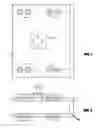
BRIEF DESCRIPTION OF DRAWINGFIG. 1 shows front view of template with drill bushings 2.
FIG. 2 shows right end view of the template with two parallel plates 3 attached together, eight drill bushings 2 in each side of the parallel plates opposite each other and a swivel compression clamp 4.
DETAILED DESCRIPTION OF THE INVENTIONThis invention is a drilling template used to drill the holes in top area of the door on the hinge side of the door to install a door closer. The drilling template body is generally designated 1 as shown in FIG. 1 and has two parallel plates 3 attached together as shown in FIG. 2 and generally consists of eight drill brushings in each parallel plate located opposite each other used to drill both sides of the door for a regular mount closer or parallel mount closer requiring sex bolts and a swivel compression clamp 4 as shown in FIG. 2.
Claims
1. What I claim as my invention is . . . “A drill template used for drilling the top area of the door on the hinge side of the door for the application of door closer.”
Images & Drawings included:

Sources:
- United States Patent and Trademark Office - verify current appl. status at the USPTO↗
Similar patent applications:
- » 20150367424
Drilling Template, Drilling Template Arrangement And Method For Introducing Bores - » 20130302752
Dental impression, drilling template and method for providing a relative location for creating a drilling template - » 20220401116
Bone anchor with a drilling template connecting to this bone anchor and method for manufacturing the bone anchor and the drilling template - » 20180132870
Bone anchor with a drilling template connecting to this bone anchor and method for manufacturing the bone anchor and the drilling template - » 20060013662
Multi-layer drilling template and method of drilling using the template - » 20210307875
DRILL TEMPLATE FOR DRILLING AN IMPLANT HOLE FOR A DENTAL IMPLANT - » 20120191421
Oral Template for Integrated CT and Optical Images for Dental Implant Drilling Templates and Orthodontic Aligners - » 20060133902
Drilling template - » 20070098508
Adjustable drill template - » 20090274527
Drilling templates
Recent applications in this class:
- » 20250162044 2025-05-22
ROTARY TOOL GUIDE - » 20250121440 2025-04-17
CUTTING AND DRILLING GUIDES FOR THE CONSTRUCTION OF WOOD STRUCTURES - » 20250091140 2025-03-20
Metal Sheet Screw Position Template - » 20250073788 2025-03-06
CONCEALED HINGE BORING JIG - » 20240416432 2024-12-19
ADJUSTABLE BUSHING ASSEMBLY FOR HOLE LOCATION AND DRILLING - » 20240408679 2024-12-12
Mounting Bracket Template Support and Method - » 20240399468 2024-12-05
SELF-ADJUSTING POCKET HOLE JIG SYSTEM - » 20240300031 2024-09-12
GAUGE PLATE FOR DRILLING ACCOMMODATION HOLE - » 20240253131 2024-08-01
Door Lock Installation Jig - » 20240227037 2024-07-11
DEVICE FOR ASSISTANCE IN DRILLING A BOARD