Method for feeding an injection material under pressure, a method for blasting using the method, a device for pressurized feeding an injection material under pressure, and a blasting device having the device
US20070010174A1
2007-01-11
11/175,604
2005-07-05
Abstract:
To provide an injection material pressurized feeding method to stably supply a fixed quantity of an injection material without aggregation and consolidation of the injection material even if the injection material having small particle diameter is used for blasting.
A fixed quantity of the injection material is introduced from the injection material tank 2 to a cylindrical pressurizing tank 11 provided between the injection material tank 2 of the blasting device 1 and a blast nozzle, and introduction of compressed stirring gas is started at a deposition part of the injection material introduced in the pressurizing tank 11 then the injection material is stirred in the pressurizing tank 11, and an inside of the pressurizing tank 11 is pressurized by starting introduction of compressed pressurizing gas from a pressurizing tank side wall 11b, thereby the injection material in the state of stirring is pressure-fed to the blast nozzle.
Inventors:
- Keiji MASE 44 🇯🇵 Tokyo, Japan
- Shozo Ishibashi 23 🇯🇵 Tokyo, Japan
- Katsuyuki Sakuma 3 🇯🇵 Tokyo, Japan
Interested in similar patents?
Get notified when new applications in this technology area are published.
Classification:
B24C7/0046 » CPC main
Equipment for feeding abrasive material; Controlling the flowability, constitution, or other physical characteristics of abrasive blasts the abrasive material being fed in a gaseous carrier
B24C1/00 IPC
Methods for use of abrasive blasting for producing particular effects; Use of auxiliary equipment in connection with such methods
B24C7/00 IPC
Equipment for feeding abrasive material; Controlling the flowability, constitution, or other physical characteristics of abrasive blasts
Description
BACKGROUND OF THE INVENTION Field of the InventionThe present invention relates to a method for feeding an injection material under high pressure (hereinafter simply called “pressurized feeding” for feeding an object under pressure) and a device for pressurized feeding an injection material under pressure, more particularly relates to a method for pressurized feeding of an injection material, a device for pressurized feeding of the same, a method for blasting using said method, and a blasting device for pressurized feeding of an injection material whereby enabling to supply the injection material by a fixed quantity stably in a blasting using injection materials comprising microscopic particles, and a product formed by said method for blasting.
A blasting performs various treatments such as cutting, polishing, blast cleaning, burring, coat formation, decoration such as satin process, shot peening treatment, however, in recent years, the blasting is widely used for microscopic treatment such as formations of a partition for a back plate of a PDP (a plasma display), pins and grooves for a micro-reactor, vacuum fastener, electrostatic fastener, a surface of a silicon wafer or the like.
Injection materials having particle diameters smaller than those of the conventional ones such as microscopic particles are used in the microscopic treatment. However, concerning such injection materials having small particle diameters, adhesion and aggregation among injection materials are tend to be increased and flowability is tend to be decreased compared to injection materials having large particle diameters. Generally, it is said that adhesion and aggregation per unit volume of particles are increased by being inversely proportional to the square of particle diameters, accordingly, adhesion and aggregation of particles are strengthened as the particle diameter is decreased.
Especially, a blasting device of a direct pressure type is constituted so that injection materials in the pressurizing tank is pressurized and stirred then injected by introducing compressed gas in the pressurizing tank, accordingly, if the injection materials are particles, “consolidation” of which aggregation of the injection materials is further strengthened by the pressurization is tend to be generated. If such consolidation is generated, a part of the injection materials is remained to be deposited in the pressurizing tank, accordingly, a supplied amount of the injection material is increased, or, the injection materials after consolidation are remained as small lumps even if the injection materials are pulverized by impact or the like, and the small lumps of the injection material are accumulated in a flow path for the injection material, thereby problems such that unevenness of injection is generated or the blast nozzle is blocked or the like are caused.
Therefore, in the blasting device of direct pressure type, high injection energy can be obtained by the presence of the pressurizing tank, however, aggregation is generated by the pressurization in case a particle size is #240 (particle diameter of 57 μm), if the particle is smaller than #1000 (11.5 μm), there is a problem that a state of which the particles cannot be injected is generated.
To solve such problems, various injection material pressurized feeding methods to suitably inject particles if the injection materials comprises microscopic particles is examined and as one example of such inventions, an injection material supply device as shown in FIG. 6 is exemplified.
In an injection material supply device 210 shown in FIG. 6, a feeding pipe 246 penetrating between side walls of the pressurizing tank 245 is provided at a position above a deposit position of the injection material in a pressurizing tank 245 in which an injection material is fed. In addition, injection port 248 opening upward is arranged at a bottom part of the pressurizing tank 245 and the injection material deposited in the pressurizing tank 245 is stirred and floated by compressed gas introduced from an injection port 248, and an inside of the pressurizing tank 245 is pressurized, thereby pressure difference is generated in the pressurizing tank 245 and the feeding pipe 246, then the injection material is flown to the injection material supply port 243 together with atmosphere in the pressurizing tank 25 in the feeding pipe 246 then pressure-fed to the blast nozzle.
The pressurizing tank 245 is constituted so that the injection material can be moved to the injection port 248 even if injection materials therein are particles and the injection materials fall along the inclined surface by inclining a lower inner wall to the bottom in an inner peripheral direction, furthermore, the pressurizing tank 245 is mounted on an oscillation generator 260 generating oscillation by introducing compressed air in the pressurizing tank 245, the injection material adhered to the inner wall of the pressurizing tank 245 is suitable fallen by oscillating the pressurizing tank 245 in upper and lower directions with the oscillation generator 260 when pressurized feeding the injection material.
In addition, there is a method that a new surface is formed by injecting and colliding the injection materials on a surface of a workpiece with injection energy of blasting.
For example, a self-lubricating surface is formed by injecting for example a solid lubricant such as molybdenum disulfide, graphite. Furthermore, there is a method that metal such as tin, titanium is injected to form a new surface as a useful technique in an industry.
In general, in mechanical element parts requiring friction resistance and wear resistance such as a sliding product, a lubricant layer is formed on the surface so as to perform a friction resistance property and a wear resistance property for a long time. As a forming method of such lubricant layer, there is a method to apply liquid lubricants such as lubricant oil or grease on the surface, however, the method is restricted depending on a use environment, for example, a lubricant effect cannot be performed under a condition of vacuum, extremely high temperature, extremely low temperature. For the above reason, a method to form a lubricant layer by not using the liquid lubricant but using a solid lubricant such as graphite, molybdenum disulfide (MOS2), tungsten disulfide (WS2), polytetrafluoroethylene (PTFE), boron nitride, or a high polymer material such as fluorine resin.
As a lubricant layer forming method by using the solid lubricant or the like, a method to coat the solid lubricant on a surface of a workpiece with a binder then dry the surface, a method to roughen a surface of the workpiece and arrange the solid lubricant then print, a method to disperse the solid lubricant to the surface the workpiece by using vacuum evaporation technique such as ion plating, sputtering technique or the like is generally used.
In addition, as a method to form the lubricant layer by injecting powders of raw material for solid lubricant to the member directly then being collided, there is a method to form a coating of molybdenum disulfide on a product to be treated by injecting molybdenum disulfide powders (see manuscripts for tribology consultation, Tokyo, 2003-5, E19; Japanese tribology institute), a method to form a coating of graphite on the product to be treated by injecting graphite powders at high speed. Any of these methods to pressure-feed injection materials is a siphon type (suction type), and it is not a blasting method of direct pressure type using the pressurizing tank by utilizing high injection energy and high efficiency energy.
According to an injection material supplying device 210 described in the Japanese Patent LOPI (KOKAI) No. 2003-25228, the injection materials in the pressurizing tank 245 are stirred and floated, thereby the injection materials are circulated stably, accordingly, if particles having small particle diameter are used, the above mentioned adhesion and/or aggregation can be prevented, therefore desired microscopic treatment can be carried out. That is, microscopic particles having particle diameter of about #3000 (4.0 μm) which is smaller than particle size of #300 to 400 (particle diameters of 50 to 60 μm) can be used as the injection materials.
However, even in the injection material supply device 210 described in the Japanese Patent LOPI (KOKAI) No. 2003-25228, if using microscopic injection materials having smaller particle diameter than particle size of #3000 (particle diameter of 4.0 μm), stability of injection is lost, thereby a problem such as deposition according to consolidation or clogging by aggregation is generated.
A particle size is varied depending on a measuring method. Therefore, in the present specification, the particle size is defined by an electric resistance test method of JIS R6001 (1998) (a particle diameter of a point of accumulation heights of 50% (dv-50 value) is 4.0 μm).
By introducing compressed gas from the injection port 248, the injection materials deposited on an upper portion of the injection port 248 and a peripheral part of the upper portion are suitably stirred, floated then circulated. However, the injection material which is deposited on a portion which is outer than the upper portion (near the inner wall) is strongly aggregated by increasing pressure in a pressurizing tank before the injection materials are blown up due to the compressed gas, then the injection materials are consolidated in the pressurizing tank as indicated in dotted lines shown in FIG. 6.
Due to consolidation of the injection materials at an outer peripheral part of the injection port 248 in the pressurizing tank 245, there are problems such that the injection material cannot be fed thereby effective application of the injection materials can not be intended, and supplied amount of the injection material becomes unstable, accordingly, it affects to treatment accuracy.
If consolidated injection materials are broken by an oscillation generator 260, the injection materials are dispersed as small lumps as different from the injection material stirred near the injection port 248. Accordingly, the lumps are accumulated in a flow path for the injection material or the blast nozzle are clogged with the injection materials, thereby problems that stably injection of the injection materials are inhibited, furthermore, the injection materials cannot be injected are generated.
In addition, in the microscopic treatment, injection materials having smaller particle diameter than those of conventional ones such as microscopic particles are used, however, in the injection material having small particle diameters, adhesion and aggregation among injection materials are tend to be increased and flowability is tend to be decreased compared to injection materials having large particle diameters. Generally, it is said that adhesion and aggregation per unit volume of particles are increased by being inversely proportional to the square of particle diameters, accordingly, adhesion and aggregation of particles are strengthened as the particle diameter is decreased.
Therefore, to solve the conventional problem, an object of the present invention is to provide an injection material pressurized feeding device and an injection material pressurized feeding method enable to supply injection materials suitably which can prevent an aggregation and consolidation of injection materials suitably and also prevent formation of “small lumps” if using particles having smaller particle size than particle size of #3000 (particle diameter of 4.0 μm) as injection materials.
SUMMARY OF THE INVENTIONIn order to achieve the above objects, an injection material pressurized feeding method of the present invention comprises the steps of introducing a fixed quantity of injection materials from an injection material tank 2 of a blasting device 1 to an inside of a cylindrical pressurizing tank 11 provided between the injection material tank 2 and a blast nozzle, starting introduction of compressed stirring gas at a deposition part for the injection material introduced from the pressurizing tank 11, starting introduction of compressed pressurizing gas from a pressurizing tank side wall 11b to pressurize the inside of the pressurizing tank 11, and pressurized feeding the injection material of a state of stirring to the blast nozzle.
It is preferable that introduction of the compressed pressurizing gas to the inside of the pressurizing tank 11 is started later than introduction of the compressed stirring gas, furthermore, it is also preferable that pressure of the compressed pressurizing gas is lower that that of the compressed stirring gas.
It is preferable that in the injection material pressurized feeding method of the present invention swirling flow along the pressurizing tank inner wall 11b′ is generated in the pressurizing tank 11 with the compressed pressurizing gas, for example, a cylinder 17 having a diameter smaller than an inner diameter of the pressurizing tank 11 is provided in the pressurizing tank 11 so that the swirling flow is generated by introducing the compressed pressurizing gas between the pressurizing tank inner wall and the cylinder outer wall.
Moreover, oscillation may be given to the pressurizing tank 11, or the inside of the pressurizing tank 11 may be heated.
A blasting method according to the present invention is characterized in that the injection material which is pressure-fed by the method according to the present invention is injected on a workpiece, and a blasting product according to the present invention is characterized in that to form a new surface layer or coat, especially a lubricant layer by injecting the injection materials having particle size of #3000 (a particle diameter of 4.0 μm) or smaller in the blasting method
Further, the injection material pressurized feeding device 10 according to the present invention comprises a pressurizing tank 11 which is provided between an injection material tank 2 of the blasting device 1 and a blast nozzle to introduce the injection material from the injection material tank 2, and the pressurizing tank 11 comprises an introduction part for compressed stirring gas opening (22) at a deposition part of the injection material introduced in the pressurizing tank 11, an introduction pipe for compressed pressurizing gas opening (24) in a pressurizing tank side wall positioned above an opening position of the introduction portion for the compressed stirring gas, a feeding pipe opening (25) in the pressurizing tank and communicating with the blast nozzle, and a compressed gas supply means to supply compressed gas in the introduction part 12 and the introduction pipe 14.
It is preferable that the compressed gas supply means comprises a start delaying means 51 to supply the compressed gas to the introduction pipe 14 for the compressed pressurizing gas later than supply of the compressed gas to the introduction part 12 for the compressed stirring gas.
It is preferable that the compressed gas supply means comprises a pressure adjuster 54 to supply compressed pressurizing gas to the introduction pipe 14 for the compressed stirring gas, and a pressure of the compressed gas supplied to the introduction pipe 14 is lower than that of the compressed gas supplied to the introduction part 12.
It is preferable that the introduction part 12 of the compressed stirring gas comprises a guide member opening to a plurality of stirring ports 22, and as the guide member, for example, a guide plate 21 on which a plurality of the stirring port 22 is provided and arranged at a bottom part of the pressurizing tank 11, and a guide pipe 28 forming a stirring port 22 by branching and opening points of the pipe into plural branched pipes in the pressurizing tank 11 are exemplified.
It is preferable that the pressurized tank inner wall 11b′ is swelled and inclined to the bottom part of the pressurizing tank 11 in outer peripheral direction.
Furthermore, it is preferable that the injection material tank 10 is constituted so that the compressed pressurizing gas introduced in the pressurizing tank 11 via the introduction pipe 14 generates swirling flow along the pressurizing tank inner wall 11b′.
As one example, the introduction pipe 14 for the compressed pressurizing gas is provided in a direction of which the compressed pressurizing gas introduced through the introduction pipe generates swirling flow along the pressurizing tank inner wall 11b, or a swirling induction body is provided in the pressurizing tank inner wall 11b in a direction of which the compressed pressurizing gas introduced in the pressurizing tank generates the swirling flow along the pressurizing tank inner wall 11b′. As the swirling induction body, for example, projections such as vanes or grooves for facilitating flow of compressed pressurizing gas is exemplified.
Furthermore, it may be configured that the cylinder 17 having an inner diameter smaller than that of the pressurizing tank 11 is provided in the pressurizing tank with spacing from the pressurizing tank inner wall 11b′ to generate the swirling flow along the pressurizing tank inner wall 11b′ between the cylinder outer wall 17′ and the pressurizing tank inner wall 11b′ by the compressed pressurizing gas introduced in the pressurized tank 11.
It is preferable that the bottom part of the cylinder 17 has an almost inverted conical shape as it goes downwardly. Furthermore, a swirling induction body may be provided on the outer wall 17b′ of the cylinder 17 in the direction of which the swirling flow is generated.
It is preferable that the feeding pipe 15 is provided at an extension of a swirling direction of the swirling flow if the swirling flow for compressed pressurizing gas is generated in the pressurizing tank 11.
It is preferable that the injection material pressurized feeding device 10 according to the present invention comprises an oscillation generator to give oscillation to the pressurizing tank 11 or a heater to heat the inside of the pressurizing tank 11.
Furthermore, a blasting device 1 according to the present invention comprises the injection material pressurized feeding device 10 of the present invention.
The injection material pressurized feeding method and the injection material pressurized feeding device 10 according to the present invention is constituted so that compressed stirring gas and compressed pressurizing gas are introduced independently in the pressurizing tank 11, thereby the injection materials are stirred by the compressed stirring gas introduced in the deposition part of the injection materials and the inside of the pressurizing tank 11 is pressurized by the compressed pressurizing gas introduced from the side wall 11b of the pressurizing tank 11 with maintaining a state of stirring of the injection material.
Furthermore, pressure in the pressurizing tank 11 becomes high with the compressed stirring gas and compressed pressurizing gas, accordingly pressure difference is generated between the pressurizing tank 11 and the feeding pipe 15 provided on an upper portion of the pressurizing tank 11, therefore, injection materials stirred and suitably dispersed in the pressurizing tank 11 are pressure-fed to the feeding pipe 15 together with these compressed gas (atmosphere in the pressurizing tank 11) with maintaining a dispersed state.
Therefore, aggregation of the injection materials can be suitably prevented, and generation of “small lumps” generated by the aggregation can be prevented and deposition of the injection materials in an inside of the pressurizing tank 11 of the injection material pressurized feeding device 10 and an inside of the feeding pipe 15 leading to the blast nozzle and other flow paths for the injection material, accordingly, a fixed quantity of the injection material can be suitably injected without generating unevenness of injection and/or clogging of the blast nozzle. In addition, deposition and/or accumulation of the injection materials can be suitably prevented. Therefore, the injection material can be efficiently used.
Furthermore, in starting, an inside of the pressurizing tank 11 can be pressurized with maintaining the state of stirring suitably in a state of which stirring of the injection material in the pressurizing tank 11 is preliminary completed with shifting timings to introduce the compressed stirring gas and the compressed pressurizing gas in the pressurizing tank 11 then starting introduction of the compressed pressurizing gas after introducing compressed stirring gas. Thereby, more suitable stirred and dispersed state of the injection material can be obtained
Moreover, pressure difference between the compressed stirring gas and the compressed pressurizing gas is provided then pressure of the compressed pressurizing gas is set lower than that of the compressed stirring gas, thereby stirring action of the injection material by the compressed stirring gas can be prevented from being impaired by the compressed pressurizing gas, and the inside of the pressurizing tank 11 can be pressurized with carrying out stirring and dispersion of the injection material.
In the injection material pressurized feeding device 10 to realize the injection material pressurized feeding method, it is constituted that an introduction part 12 for compressed stirring gas to introduce the compressed stirring gas in the pressurizing tank 11 comprises a guide member opening at plural stirring ports 22 such as a guide plate 21 or a guide pipe 28, thereby the injection material deposited in the pressurizing tank 11 by compressed stirring gas introduced from the stirring ports 22 can be blown up then stirred throughout the pressurizing tank 11 and consolidation of the injection material due to deposition thereof can be prevented suitably.
In addition, by providing an inner wall 11b′ of the pressurizing tank 11 so that the inner wall 11b′ is swelled and inclined to a bottom part of the pressurizing tank 11, so-called divergent-shaped, when the injection material floated in the pressurizing tank 11 is adhered to an inner wall of the pressurizing tank 11, the injection material can be fallen, thereby adhesion of the injection material can be prevented suitably.
Furthermore, swirling flow along the pressurizing tank inner wall 11b is generated in the pressurizing tank 11 with the compressed pressurizing gas, thereby the injection material in the pressurizing tank 11 is swirled on the swirling flow, accordingly more good dispersion state of the injection material can be obtained.
In the injection material pressurized feeding device 1, an installation direction of the introduction pipe 14 for compressed pressurizing gas to introduce the compressed pressurizing gas in the pressurizing tank 11 is adjusted, the cylinder 17 is arranged in the pressurizing tank, or a swirling induction body is provided on the pressurizing tank inner wall 11b′ or the cylinder outer wall 17′, thereby flow of compressed pressurizing gas is induced, then the swirling flow can be generated suitably.
Furthermore, at this time, if the swirling flow of the feeding pipe 15 is arranged at an extension of a swirling direction, the injection material circulated in the pressurizing tank 11 by the compressed stirring gas and the compressed pressurizing gas can be pressure-fed to the feeding pipe 15 smoothly with maintaining a suitable dispersion state.
In addition, aggregation of the injection material or adhesion/deposition to the inside of the pressurizing tank 11 can be suitably prevented by applying oscillation to the pressurizing tank 11 or heating the inside of the pressurizing tank, therefore good dispersion state of the injection material can be obtained.
According to the injection material pressurized feeding method and injection material pressurized feeding device 10 mentioned above, the injection material can be dispersed to a desired state, and aggregation of the injection material can be suitable prevented, therefore, in the blasting method to inject the injection material pressure-fed by the injection material pressurized feeding method, or the blasting device providing the injection material pressurized feeding device, particles having smaller particle diameter than particle size of #3000 (particle diameter of 4.0 μm) which is an minimum particle diameter in the invention of Japanese Patent LOPI (KOKAI) No. 2003-25228 can be used, thereby the injection material can be pressure-fed to the blast nozzle by a fixed quantity suitably.
Therefore, in the blasting method and blasting device, particles having particle diameters of about particle size of #150 (particle diameter of 69 μm) to particle size #30000 (particle diameter 0.1 μm), preferably, particle size of #240 (particle diameter of 57 μm) to particle size of #15000 (particle diameter of 0.3 μm) can be used.
Material of the injection material used in the present invention is not especially restricted and metal, resin, ceramics or the like can be widely used and as the shape of the injection material, the various shape such as an angulate shape as well as spherical shape can be employed.
Various microscopic treatments can be suitably carried out by using particles having small particle diameters as the injection materials as mentioned above, therefore, a blasting product on which blasting is carried out by injecting the injection materials has high treatment accuracy and good finish quality.
BRIEF DESCRIPTION OF THE DRAWINGSThe objects and advantages of the invention will become apparent from the following detailed description of preferred embodiments thereof provided in connection with the accompanying drawings in which:
FIG. 1 is a drawing showing a part of a blasting device in an embodiment according to the present invention;
FIG. 2 is a sectional view of A-A′ line of FIG. 1;
FIG. 3 is a schematic sectional view of B-B′ line of FIG. 1;
FIG. 4 is a drawing showing one embodiment of a supply circuit of compressed gas in the present invention;
FIG. 5 is a drawing showing a part of an injection material pressurized feeding device in another embodiment according to the present invention; and
FIG. 6 is a drawing showing a conventional blasting device.
PREFERRED EMBODIMENT OF THE INVENTIONAs an embodiment of the present invention, an injection material pressurized feeding device for realizing the injection material pressurized feeding method, and a blasting device providing the injection material pressurized feeding device will be described with reference to attached drawings below.
1. Injection Material Pressurized Feeding Device
The injection material pressurized feeding device 10 is provided between the injection material tank 2 of the blasting device 1 and a blast nozzle, and the injection material circulated in the blasting device 1 is stirred and dispersed in the desired state, then pressure-fed to the blast nozzle.
In an embodiment shown in FIGS. 1 to 3, the injection material pressurized feeding device 10 of the present invention comprises the pressurizing tank 11 to contain the injection materials, the cylinder 17 provided vertically in the pressurizing tank 11, and the oscillation generator 18 attached on an outer wall of the pressurizing tank 11. Furthermore, the injection material pressurized feeding device 10 comprises an introduction part 12 for compressed stirring gas of the pressurizing tank 11 described later and a compressed gas supply means to supply compressed gas to an introduction pipe 14 for the compressed pressurizing gas. Furthermore, the pressurizing tank 11 is arranged at an upper portion of the pressurizing tank 11 through a dump valve 6. In addition, the pressurizing tank 11 is suspended in a casing 3 through a spring 5 so as to prevent the other devices from being affected by oscillation generated with the oscillation generator 18.
Pressurizing Tank
The pressurizing tank 11 functions as a pressure vessel of which an inside of the vessel is pressurized by introducing compressed gas. In the present embodiment, the pressurizing tank 11 has almost cylindrical shape and an introduction part 12 (hereinafter referred to as “stirring port”) for compressed stirring gas can be provided at a bottom part of the pressurizing tank 11, furthermore, an introduction pipe 14 (hereinafter referred to as “pressurizing pipe”) for compressed pressurizing gas is provided in a pressurizing tank side wall 11b which is provided above the introduction part 12 for the compressed stirring gas.
A feeding pipe 15 communicating with a blast nozzle of the blasting device 1 is further provided on the pressurizing tank side wall 11b provided above the pressurizing pipe 14, and a discharge pipe 16 for discharging atmosphere (compressed gas) in the pressurizing tank 11 to release a pressurizing state in the pressurizing tank 11 when feeding the injection material in the pressurizing tank 11 is also provided.
A shape of the pressurizing tank 11 is not limited to a cylindrical shape and any shapes may be employed, for example, the tank may be a tubular body or the like comprising a bottom portion 11c and an top portion 11a having polygonal shape may be employed, as long as it can pressure-feed the injection material to the blast nozzle by stirring the injection material contained in the pressurizing tank 11 then pressurizing the inside.
Furthermore, the inner wall of the pressurizing tank 11 may be provided vertically, however, it is preferable to be formed into a shape broaden toward the end with being inclined slightly toward an outer peripheral direction as the tank directed to the bottom portion. Thereby, if the injection material floated in the pressurizing tank 11 is adhered to the inner wall of the pressurizing tank 11, the injection material can be fallen. The inclined angle can be appropriately adjusted within a range of which the inclined angle enable to prevent adhesion of injection material of the inner wall, for example, 0° to 30°.
In the present invention, the stirring part 12 to introduce the compressed stirring gas in the pressurizing tank 11, and the pressurizing pipe 14 to introduce compressed pressurizing gas are provided independently. Thereby, the injection material deposited in the pressurizing tank 11 by a compressed stirring gas introduced from the stirring part 12 is stirred and the inside of the pressurizing tank 11 can be pressurized as the compressed pressurizing gas is dispersed to the desired state with maintaining a state of stirring of the injection material with compressed pressurizing gas introduced from the pressurizing pipe 14. Therefore, unlike the invention according to Japanese Patent LOPI (KOKAI) No. 2003-25228 introducing only compressed stirring gas from a lower portion of the pressurizing tank 11, in the present invention, injection material can be supply stably to a blast nozzle by a fixed quantity in the pressurizing tank 11 without deposition and consolidation of the injection material.
There is no strict distinction between the compressed stirring gas and the compressed pressurizing gas, and the both compressed gases have actions to stir, float then disperse the injection material in the pressurizing tank 11 in a desired state by pressurizing the inside of the pressurizing tank 11. In the present invention, the gas introduced to stir and float the injection material deposited in the pressurizing tank 11 is called as compressed stirring gas, and the gas introduced to further disperse the injection material in the floating state is called as compressed pressurizing gas.
As compressed gasses used in the present invention such as compressed stirring gas and compressed pressurizing gas, any gasses can be used as long as it does not affect to blasting such as deterioration of the injection material, however, in the present embodiment, compressed air is used.
Stirring Part
The stirring part 12 is opened to stirring ports 22 at a deposition part of the injection material to stir the deposited injection material in the pressurizing tank 11. Here, the deposition part of the injection material includes an inside of the deposited injection material as well as portions connected with the injection material deposited in the pressurizing tank 11.
It is allowable that the number of the stirring ports 22 is one, however, it is preferable to provide a plurality of the stirring ports 22 to blow up the injection material thoroughly and stir the material.
In addition, the stirring part 12 may be constituted so that the stirring ports 22 are directly provided on the pressurizing tank bottom portion 11c or near the bottom portion 11c of the pressurizing tank side wall 11b, then constituted compressed gas is supplied from a compressed gas supply means to the stirring ports 22 after that compressed stirring gas is introduced in the pressurizing tank. However, the stirring part 12 may be formed by providing guide members such as a guide plate 21 having the stirring ports 22 or a guide pipe 28 in the pressurizing tank 11.
In an embodiment shown in FIG. 2, it is constituted so that a guide plate 21 as a plate shaped body on which a plurality of stirring ports 22 is provided is used as a guide member, a chamber 23 is formed between the guide plate 21 and the bottom portion by providing the guide plate 21 almost parallel to the bottom portion 11c of the pressurizing tank 11 with spacing the predetermined interval, and compressed stirring gas is supplied in the pressurizing tank 11 via the stirring ports 22 of the guide plate 21 provided on the chamber 23 by supplying compressed gas from a supply pipe 13 communicating with the pressurizing tank bottom portion 11c to the chamber 23.
Concerning a guide plate 21 provided on an upper portion of the pressurizing tank bottom portion 11c, the material or thickness, the number of stirring ports 22, shapes, size, or provided position or direction (angle) of the stirring ports 22 or the like can be changed appropriately, as long as the compressed stirring gas can be suitably introduced in an upper portion of the pressurizing tank 11. In addition, a porous material such as ceramics or the like may be used without providing the stirring ports 22 artificially as of the present embodiment.
As an arrangement example of the stirring ports 22, the stirring ports 22 are provided on a circle having a predetermined radius from a center of the guide plate 21 with spacing at predetermined intervals, or, the stirring ports 22 is provided on concentric circles having different radiuses with setting their center to the center of the guide plate 21, as well as on the one circle, with predetermined interval, or, the stirring ports 22 are provided on a straight line extended radially from the center or, on a curved line curved to the predetermined direction from the center with the predetermined interval. Otherwise, the stirring ports 22 are provided on a plurality of straight lines positioned almost in parallel with spacing the predetermined intervals, and especially, the stirring ports 22 can be provided on the guide plate 21 in whole at random without specific installation standard.
Furthermore, as shown in FIG. 1, in the present embodiment, the installation direction (angle) the stirring ports 22 is almost vertical, however, the direction is not restricted especially as long as the injection material can be blown up and suitably stirred by introducing the compressed stirring gas in the pressurizing tank 11, and the stirring ports 22 may be provided with being inclined at the predetermined angle toward the upper portion of the guide plate 21 facing to the inside of the pressurizing tank 11 from the lower portion of the guide plate 21 facing to the chamber 23. For example, if all of the stirring ports 22 are provided with being inclined at the predetermined angle in the same rotary direction, generation of swirling flow in the pressurizing tank 11 later described can be facilitated.
In the present embodiment, it is constituted so that the chamber 23 is formed by providing a space between the pressurizing tank bottom portion 11c and the guide plate 21, thereby compressed gas is supplied from the supply pipe 13 communicating with the pressurizing tank bottom portion 11c to the stirring ports 22 of the guide plate 21 via the chamber 23, however, it is allowable as long as a supply path for a compressed gas from the supply pipe 13 to the stirring ports 22 of the guide plate is provided, for example, it is permissible that compressed gas is supplied from the supply pipe 13 to the stirring ports 22 of the guide plate 21 superimposed on the bottom portion 11c by providing grooves on the bottom portion 11c.
Furthermore, in the present embodiment, the guide plate 21 made of a plate-shaped body is used as a guide member, however, any material can be used as a guide member such as a film-shaped body or a network-shaped body or the like can be used as a guide member not restricted to the plate-shaped body, as long as compressed stirring gas can be introduced in the pressurizing tank 11 from the stirring ports 22.
The guide member used in the embodiment of FIG. 2 is a guide plate 21 to stir the injection material deposited in the pressurizing tank 11 from the outside, however, a guide pipe 28 or the like introducing compressed stirring gas from an inside of the injection material deposited in the pressurizing tank 11 may be used as the guide member.
In an embodiment shown in FIG. 5, a supply pipe communicating with the pressurizing tank bottom portion 11c is penetrated to an upper portion of the bottom portion as it is and, the supply pipe is branched into plural branched pipes toward the predetermined directions, then the guide pipe 28 is made by opening points of the branched pipes then providing stirring ports 22 thereon, thereby compressed stirring gas is introduced in the pressurizing tank 11 from the guide pipe 28.
In FIG. 5, the guide pipe 28 is branched toward vertical and horizontal directions, however, as long as the injection materials in the pressurizing tank 11 can be suitably stirred, there is no restriction concerning the number of branched pipes and branched directions of the guide pipe 28 or the like specifically, and the pipe may be branched upwardly, for example.
Furthermore, in the present embodiment, the guide pipe 28 is made by being penetrated in the pressurizing tank bottom portion 11c in a vertical direction, otherwise, a pipe penetrating the bottom portion 11c of the pressurizing tank side face 11b and extends along the bottom portion 11c in the pressurizing tank 11, and a plurality of stirring ports 22 is provided at the side of the pipe or the like may also be used as the guide pipe 28.
Moreover, a plurality of formation patterns of the stirring ports 22 may be combined for use, and as long as the stirring part 12 has a structure enables to blow the injection material in the pressurizing tank 11 upwardly, a structure of the stirring part 12 in the injection material pressurized feeding device 10 according to the present invention is not restricted to the aforementioned structure.
Pressurizing Pipe
A pressurizing pipe 14 to introduce compressed gas to pressurize the inside of the pressurizing tank 11 with maintaining the injection material stirred in the pressurizing tank 11 by compressed stirring gas is opened at a side wall of the pressurizing tank 11 above the stirring ports 22 of the stirring part 12 provided on an injection material deposition part of a bottom of the pressurizing tank 11. In the present embodiment, as shown in FIG. 1, one pressurizing pipe 14 opening at the pressurizing port 24 is provided at an almost center of the total height of the pressurizing tank 11.
The number of the pressurizing pipe 14 and the arranged angles thereof or the like may be changed appropriately without any restriction as long as the aforementioned effect can be obtained, however, in cooperation with compressed stirring gas introduced from the stirring part 12 of a lower portion of the pressurizing tank 11, from a point of view that the injection material is pressure-fed to the supply pipe arranged above the pressurizing pipe 14, it is preferable that the pressurizing pipe 14 is arranged in a direction to supply compressed pressurizing gas in a horizontal direction or upwardly.
In addition, the pressurizing pipe 14 may be installed so that an axis line is orthogonalized with the side wall of the pressurizing tank 11, however, to facilitate generation of swirling flow in the pressurizing tank 11, for example, it is preferable that the pressurizing pipe 14 is provided so that an axis line of the pressurizing pipe 14 is arranged so as to be inclined with predetermined angle to the side wall of the pressurizing tank 11 at an installation position of the pressurizing pipe 14 as shown in FIG. 3, or if the later described cylinder 17 is provided vertically in the pressurizing tank 11, compressed pressurizing gas from the pressurizing pipe 14 is introduced along an inner wall of the pressurizing tank 11 by arranging the axis line of the pressurizing pipe 14 so as to be positioned at an extension of a tangent (direction) of a cylinder 17.
By arranging the pressurizing pipe 14 as aforementioned, swirling flow is generated in the pressurizing tank 11 by the compressed pressurizing gas introduced from the pressurizing pipe 14, the injection material in the pressurizing tank 11 is swirled on this swirling flow, therefore, the injection materials can be dispersed in a desired state, moreover, the injection material can be easily pressure-fed to the feeding pipe 15 provided in the pressurizing tank 11.
Feeding Pipe
A feeding pipe 15 is constituted to pressure-feed the injection material stirred by compressed stirring gas and compressed pressurizing gas introduced in the pressurizing tank 11 then dispersed in the desired state to a blast nozzle (not shown) of the blasting device 1 together with atmosphere in the pressurizing tank 11.
In the present embodiment, as shown in FIGS. 1 to 3, at the side wall 11b near a top portion 11a of the pressurizing tank positioned upper than the pressurizing pipe 14, the feeding pipe 15 is opened at a feeding port 25, and arranged at a position symmetric about the pressurizing pipe 14, thereby the injection material blown up to an upper of the pressurizing tank 11 by the compressed stirring gas then stirred can be easily pressure-fed, however, as long as the position is enable to pressure-feed the injection materials by the compressed pressurizing gas, a position on which the pipe is opened is not especially restricted, and the position may be a pressurizing tank side wall 11b or a pressurizing tank top portion 11a or the like, in addition, for example, installation positions of the pressurizing pipe 14 and the feeding pipe 15 may be reversed.
Concerning the feeding pipe 15, the installation direction, installation angle or the like can be changed appropriately, however, to pressure-feed the injection material in the pressurizing tank 11 smoothly, same as the pressurizing pipe 14, for example, the axis line of the feeding pipe 15 is installed so as to be inclined at the predetermined angle at a side wall of the pressurizing tank 11 in an installation position of the feeding pipe 15, in addition, if a cylinder 17 later described is installed vertically in the pressurizing tank 11, it is preferable that the feeding pipe 15 is installed at an extension of a swirling direction of the swirling flow generated in the pressurizing tank 11 by arranging the feeding pipe 15 so that the axis line of the feeding pipe 15 is positioned at an extension of a tangent (direction) of the cylinder 17.
Compressed Gas Supply Means
A compressed gas supply means is constituted to supply compressed stirring gas and compressed pressurizing gas to the stirring part 12 and the pressurizing pipe 14 of the pressurizing tank 11, and it comprises a compressed gas supply source (not shown) and a supply circuit 40 communicating from the compressed gas supply source to a supply pipe 13 of the stirring part 12 and the pressurizing pipe 14 which are destinations of supply.
Introductions of compressed stirring gas and compressed pressurizing gas by the compressed gas supply means can be carried out simultaneously, however, it is preferable that, when the injection material pressurized feeding device 10 is started, at first, compressed stirring gas is introduced from the stirring part 12 and the injection material in the pressurizing tank 11 is blown up and stirred, then compressed pressurizing gas is introduced from the pressurizing pipe 14, thereby the inside of the pressurizing tank 11 is pressurized.
As mentioned above, by starting the introduction of compressed pressurizing gas after the introduction of compressed stirring gas, without being inhibited blowing up of the injection material with the compressed stirring gas, by the compressed pressurizing gas, with maintaining the state of stirring in a state of which the injection material in the pressurizing tank 11 is preliminarily stirred, thereby the inside of the pressurizing tank can be pressurized, and the injection material can be stirred, dispersed suitably.
Time difference between the compressed stirring gas and compressed pressurizing gas, can be changed appropriately depends on a size of the pressurizing tank 11 which is used or a quantity of the injection material, treatment conditions or the like, as one example, the time difference may be set as 3 seconds or less.
Moreover, as mentioned above, to pressurize the inside of the pressurizing tank with maintaining a state of stirring of the injection material by the compressed stirring gas, pressure difference is set between the compressed stirring gas and the compressed pressurizing gas, and it is also set that pressure of compressed pressurizing gas is lower than that of the compressed stirring gas. It is preferable that pressure difference between the compressed pressurizing gas and compressed stirring gas is controlled for example, within 0.004 to 0.03 MPa, preferably, 0.004 to 0.01 MPa. Thereby, blowing pressure of the injection material by the compressed stirring gas becomes higher than swirling pressure by the compressed pressurizing gas, therefore, the injection material is suitably blown upwardly and stirred, accordingly, the injection material can be stirred and dispersed suitably, same as time difference mentioned above.
Therefore, in the present invention, it is preferable that the start delaying means to introduce the compressed pressurizing gas later than the introduction of the compressed stirring gas and/or the pressure adjuster to introduce compressed pressurizing gas having lower pressure than the compressed stirring gas is provided in a supply circuit 40 of the compressed gas supply means.
The start delaying means and the pressure adjuster are not especially restricted to the constitution and installation position or the like as long as it can be set the time difference and pressure difference, however, for example, as the start delaying means, an electromagnetic valve 51 to control supply of compressed gas from compressed gas supply source can be used, in addition, as the pressure adjuster, a ball valve 54 or the like can be used.
Supply Circuit
FIG. 4 shows one example of the supply circuit 40, as well as supplying compressed gas from a common compressed gas supply source to the stirring part 12 and pressurizing pipe 14, it is constituted that compressed gas is supplied from the compressed gas supply source to the blast nozzle of the blasting device 1, and branched in three angles, i.e., from the compressed gas supply source to the stirring part 12, the pressurizing pipe 14 and the blast nozzle.
In this embodiment, among the supply circuits 40, the circuit from a compressed gas supply source to a branch point 46 is called as a common circuit 41, a circuit communicating from the branch point 46 to a supply pipe 13 of the stirring part 12 is called as a stirring circuit 42, a circuit communicating from the branch point 46 to the pressurizing pipe 14 is called as a pressurizing circuit 44, and a circuit communicating from the branch point 46 to a pipe arrangement leading to the blast nozzle is called as an injection circuit 48.
In embodiment shown in FIG. 4, an air filter 53 and a depressurizing valve 55 for removing dust in compressed gas supplied from the compressed gas supply source are provided in the common circuit 41, and compressed gas supplied from the compressed gas supply source is branched in three directions after passing the common circuit 41.
A stirring circuit 42, one of circuits after branching comprises, the electromagnetic valve 51 which is an opening and closing valve to control supply of compressed gas, a check valve 52 to prevent adverse current of gas, and an air filter 53 and compressed gas passed through the circuit 42 is supplied to the supply pipe 13 communicating to the stirring part 12 of the pressurizing tank 11.
As well as the stirring circuit 42, in the pressurizing circuit 44, the electromagnetic valve 51, the check valve 52 and the air filter 53 are provided, furthermore, the pressurizing circuit 44 comprises the ball valve 54 to adjust pressure between the branch point 46 and the electromagnetic valve 51.
Furthermore, the injection circuit 48 comprises a pinch valve 56 to control supply of compressed gas to the blast nozzle.
Operation of a compressed gas supply means comprising the supply circuit 40 as mentioned above will be described below. When compressed gas is supplied from the compressed gas supply source through the common circuit 41, compressed gas which is branched in the three directions from the branch point then lead to the stirring part 12 of the pressurizing tank 11 through the stirring circuit 42 is supplied from the stirring ports 22 of the stirring part 12 to the inside of the pressurizing tank 11 as compressed stirring gas, thereby, the injection material deposited in the pressurizing tank 11 is blown upwardly then stirred.
On the other hand, compressed gas supplied from the pressurizing pipe 14 through the pressurizing circuit 44 is introduced from the pressurizing pipe 14 to the inside of the pressurizing tank 11 as compressed pressurizing gas. However, in a starting time of the injection material pressurized feeding device 10 (starting time of supply of compressed gas from the compressed gas supply source), the electromagnetic valve 51 provided on the pressurizing circuit 44 is closed, thereby, introduction of the compressed pressurizing gas can be started later than introduction of the compressed stirring gas to the inside of the pressurizing tank 11 by opening the electromagnetic valve 51 after passing the predetermined time to delay supply of compressed gas to the pressurizing pipe 14.
In addition, the ball valve 54 provided in the pressurizing circuit 44 enables to adjust pressure of compressed gas supplied to the pressurizing pipe 14 and pressure of compressed pressurizing gas supplied to the pressurizing pipe 14 can be lowered than that of the compressed stirring gas.
By providing the electromagnetic valve 51 and the ball valve 52, a supply timing and pressure of compressed gas flown in the pressurizing circuit can be controlled, and the inside of the pressurizing tank 11 can be pressurized with maintaining state of stirring by compressed stirring gas suitably.
In addition, both of the stirring circuit 42 and the pressurizing circuit 44 have the check valves, thereby, if pressure in the pressurizing tank becomes high by introducing compressed stirring gas and compressed pressurizing gas, adverse current of gas can be suitably prevented.
In addition, from the compressed gas supply source, compressed gas is supplied also to the injection circuit 48, and the compressed gas is supplied leading to the blast nozzle communicating with the injection nozzle 48. The injection material pressure-fed from the pressurizing tank 11 to the feeding pipe 15 by the compressed stirring gas and compressed pressurizing gas is pressure-fed to the blast nozzle as it is, however, just before the injection material is injected from the blast nozzle, the injection material is injected to a workpiece with high injection pressure by compressed gas supplied through the injection circuit 48. Supply or non-supply of compressed gas to the blast nozzle and a supply quantity or the like can be adjusted by the pinch valve 56 provided on the injection circuit 48.
Furthermore, in compressed gas supply circuit 40 shown in FIG. 3, the case of which the compressed gas supply source which is common to the stirring part 12, the pressurizing pipe 14 and the blast nozzle is described, however, embodiments according to the present invention are not restricted thereto, and the compressed gas supply means may provide separate compressed gas supply source for the stirring part 12, the pressurizing pipe 14 and the blast nozzle respectively. In this case, difference of introduction time and/or pressure difference of compressed stirring gas and compressed pressurizing gas can be set by controlling a supply timing and supply pressure of compressed gas from the respective compressed gas supply sources.
Furthermore, if a later-described oscillation generator 18 provided on the pressurizing tank 11 of the injection material pressurized feeding device 10 generates oscillation by supplying compressed gas, the compressed gas supply circuit 40 can be constituted by supplying compressed gas is supplied from the same compressed gas supply source to the oscillation generator 18, or providing a separate compressed gas supply source is provided.
Cylinder
It is possible to disperse the injection material in a suitable state only by compressed stirring gas and compressed pressurizing gas supplied in the pressurizing tank 11. However, in order to disperse the injection material more suitably and facilitate pressurized feeding of the injection material from the feeding pipe 15, in the present embodiment, the cylinder 17 which is smaller than an inner diameter of the pressurizing tank 11 is provided in the pressurizing tank 11.
The cylinder 17 is provided to form a flow path for the compressed gas and the injection material between the inner wall 11b′ of the pressurizing tank 11 and the outer wall 17′ of the cylinder 17, and it can facilitate to generate desired swirling flow in the pressurizing tank 11.
Concerning the cylinder 17, size, shape and installation method or the like is not restricted as long as the above-mentioned object can be achieved, however, in the embodiment shown in FIG. 1, the cylinder 17 is arranged on the same axis with a central axis of the pressurizing tank 11 in order to form a flow path for the compressed gas or the like in the pressurizing tank 11 uniformly. In addition, a guide plate 21 arranged at an upper portion of a bottom portion of the pressurizing tank 11 are provided as the introduction part 12 of the compressed stirring gas, thereby the cylinder 17 is vertically provided on a top portion of the pressurizing tank 11 to prevent introduction of compressed stirring gas from the guide plate 21 due to installation of the cylinder 17.
In order to equalize stirring in the pressurizing tank 11, it is preferable that the shape of the cylinder 17 is a shape so as to form an inverted cone as the bottom part is directed downwardly, whereby avoiding a resistance for compressed stirring gas introduced from the lower portion of the pressurizing tank 11 is blown upwardly, as well as the compressed stirring gas can be induced to the flow path between the pressurizing tank inner wall 11b′ and the cylinder outer wall 17′.
Otherwise, by forming an upper portion of the cylinder 17 is formed into a conical shape, when the injection material attached to the pressurizing tank top portion 11a is fallen, it can be prevented that the injection material is attached to the upper portion of the cylinder and the injection material can be suitably stirred.
Oscillation Generator
In present embodiment, the oscillation generator 18 is provided on an outer wall of the pressurizing tank 11, to prevent the injection material stirred and floated by compressed stirring gas and compressed pressurizing gas from attached and deposited in the pressurizing tank 11 and the cylinder thereby obtain suitable dispersed state of the injection material, in addition to facilitate pressurized feeding of the injection material to the feeding pipe 15.
Concerning the oscillation generator 18, its kinds, an installation position, an installation method and the like are not restricted as long as it can give desired oscillation to the whole of the pressurizing tank 11, and an oscillation motor or an impact-type oscillation generator 18, or various well-known oscillation generator 18 such as an oscillation generator 18 using compressed gas according to Japanese Patent LOPI (KOKAI) No. 2003-25228 can be used, furthermore, the oscillation generator 18 may be arranged at a lower portion or an upper portion of the pressuring tank 11 as well as the side wall of the oscillation generator 18.
Other Additional Means
In addition, it may be provided a swirling induction body such as blades and/or grooves or the like introducing flow of the compressed stirring gas and compressed pressurizing gas introduced in the pressurizing tank 11 on the inner wall 11b′ of the pressurizing tank so that the injection material in the pressurizing tank 11 can be dispersed suitably, or the injection material can be pressure-fed to the feeding pipe 15 rapidly.
Flow of compressed pressurizing gas introduced from the pressurizing tank side wall 11b is induced by such blades or grooves, thereby, desired swirling flow can be generated in the pressurizing tank 11. The swirling induction body such as the blade or grooves may be provided on the outer wall 17′ of the cylinder 17, and may also be provided on both of the pressurizing tank inner wall 11b′ and the cylinder outer wall 17′.
Otherwise, in order to prevent the injection material in the pressurizing tank 11 from aggregating, a heater may be installed on the pressurizing tank 11 to remove moisture of the injection material. A structure and/or an installation position of the heater can not be restricted especially, as long as it can prevent the injection material from aggregating in the pressurizing tank suitably.
2. Blasting Device
The blasting device 1 according to the present invention is characterized by providing the injection material pressurized feeding device 10 according to the present invention, and concerning the other constitution, a constitution same as that of a known blasting device can be employed.
As an example, the blasting device 1 according to the present invention comprises the injection material pressurized feeding device 10 according to the present invention, the blast nozzle communicating with the feeding pipe 15 of the injection material pressurized feeding device 10 to inject injection materials to a workpiece together with compressed gas, the treatment chamber 23 containing the blast nozzle, an injection material tank 2 communicating with the treatment chamber 23 to recover and classify the injection material and dust generated by injection of the injection material then feed classified injection material to the injection material pressurized feeding device 10, and a dust collector communicating with the injection material tank 2 and collecting dust classified in the recovering tank.
In FIGS. 1 and 2, the injection material tank 2 to accumulate the injection material is installed on an upper portion of the injection material pressurized feeding device 10, and the injection material tank 2 and the pressurizing tank 11 of the injection material pressurized feeding device 10 are installed via the dump valve 6, thereby, a fixed quantity of the injection material can be fed from the injection material tank 2 to the inside of the pressurizing tank 11.
When the injection material in the pressurizing tank 11 becomes empty and then the injection material is fed from the injection material tank 2 to the pressurizing tank 11, atmosphere in the pressurizing tank 11 is discharged from the discharge pipe 16 provided on the side wall of the pressurizing tank 11 and pressure in the pressurizing tank 11 is decreased then the dump valve 6 is opened, thereby the injection material is fallen from the injection material tank 2.
Furthermore, the feeding pipe 15 communicates with the blast nozzle not shown to inject the injection material on the workpiece, and the injection material suitably dispersed by the injection material pressurized feeding device 10 is pressure-fed to the blast nozzle through the feeding pipe 15 together with high atmosphere in the pressurizing tank 11, then a fixed quantity of the injection material is suitably injected on a workpiece from the blast nozzle. In addition, injection from the blast nozzle can be carried out with compressed stirring gas and compressed pressurizing gas introduced in the pressurizing tank 11, however, it is preferable to increase injection force of the injection material from the blast nozzle by further supplying compressed gas near the blast nozzle on a pipe arrangement communicating with the blast nozzle, and in an embodiment shown in FIG. 4, it is realized by the injection circuit 48.
3. Treatment Example
A blasting product obtained by injecting microscopic injection materials by using the injection material pressurized feeding device (method) according to the present invention will be described below.
Formation of a Surface Layer
A solid lubricant to give lubricity to a surface of the workpiece can be used as the injection material injected by the blasting device according to the present invention.
As well as solid lubricants of oxide such as calcium fluoride, gold, silver, lead, lead monoxide, barium chromate, plastics such as teflons (TM), MCA (melamine cyanurate), graphite, hexagonal crystal boron nitride, diamond powders, or new carbon material such as fullerene, carbon nanopipe, carbon nano horn, molybdenum disulfide, tungsten disulfide, tin disulfide, mica, fluorination graphite, barium fluoride can be exemplified as the solid lubricant. In addition, mixture powders of them can also be used. However, graphite powders are used as the solid lubricant in the present embodiment.
As the graphite powder, it is preferable that the one having 90% or more of carbon component, and particle diameter of about 1 to 57 μm, and as kinds of the graphite powder, natural graphite such as scale-shaped graphite, earthy graphite or artificial graphite is exemplified, and in the present invention, any graphite may be used, however, in the present embodiment, graphite powders produced by Nippon Graphite Industries, ltd. called as HOP is used. HOP is graphite powders excellent in lubricity, electrically conductive and apparent density (bulk density) is 0.15 g/cm3. The graphite powders are dispersed within a range of particle diameter of 0.2 to 30 μm, and average particle diameter of the graphite powder is about 4.0 μm.
In addition, in the present embodiment, the solid lubricant is used as injection materials as mentioned above, however, injection materials for forming a layer other than a lubricant layer, injection materials for obtaining effect of cutting, polishing, shot peening or the like, or injection materials for the other various object can be used, as long as the desired effect can be obtained by injecting injection materials with fine particle on a workpiece at high injection speed, and an application according to the present invention is not limited to injection of solid lubricants.
For example, as the injection material, microscopic particles of metal having particle size of #3000 or more such as aluminum, silicon, magnesium, titanium, vanadium, chromium, manganese, iron, cobalt, nickel, copper, zinc, zirconium, neodymium, molybdenum, ruthenium, rhodium, palladium, silver, indium, tin, tantalum, tungsten, platinum, gold, are exemplified.
Furthermore, as the injection material, single kind or a mixture of two or more kinds of injection materials selected from these metals can be used. In addition, as the injection material, single kind or a mixture of two or more kinds of material selected from these oxides and a mixture made of oxide and metal or metal oxide can be used.
As injection materials, microscopic particles of ceramics having particle size of #3000 or more, such as alumina, zirconia, silicon nitride, glass, PZT, barium titanate can be employed as one example.
As injection materials, microscopic particles of thermoplastics, thermosetting plastics having particle size of #3000 or more, such as nylon, polycarbonate, polyethylen, polypropylene, polystyrene, chloroethylene, polymethyl methacryl, polyacetal, cellulose acetate can be employed as one example.
A layer of the injection material can be formed by blasting these injection materials with a device according to the present invention.
Particle diameter of the injection material may be about 1 to 57 μm, preferably, #3000 or more (4.0 μm or lower).
As a shape of the injection material, spherical shape, polygonal shape, cylindrical shape, flake shape or the like may be widely employed.
Object to be Processed
As a workpiece being subjected to blasting by injection materials injected through the injection nozzle, various materials such as metal, synthetic resin, ceramics, wood, leather, papers can be employed, the material can be selected appropriately depending on an object and/or contents of the blasting.
In the present embodiment, as a workpiece on which the graphite powders as a solid lubricant are injected then the lubricant layer is formed, for example, not only aluminum alloy, but also metal having high hardness and/or melting point than aluminum alloy such as steel can be employed. Concretely, SKD11, SUJ2, SKS, SUS440C can be exemplified as a ferreous material and A5056, A7075 can be exemplified as aluminum material.
SKD11 is a kind of alloy tool steel employed as a material for a cold die such as gage, cutting die, thread rolling dice, and SUJ2 is a kind of high carbon chromium bearing steel iron material employed for rolling bearings or the like. SKS mentioned above is alloy tool steel for cutting tool and SUS440C is martensitic stainless steels, and employed for nozzles and/or bearings and the like.
Furthermore, A5056 is aluminum alloy widely employed for various industrial products such as automobile, A7075 is referred to as extra super duralumin and excellent in mechanical properties such as intensity/treatment characteristics, and used for a frame for airplane or other material for structure or the like.
In the present embodiment, these metals subjected to lapping finish used as a workpiece.
Treatment Condition
As an injection condition, in case when the injection material is injected by the blasting device according to the present invention, it depends on materials, particle diameter and shapes of injection materials, through, injection pressure can be set as 0.01 to 5.0 MPa, for example, 0.1 to 1.0 MPa, and injection speed can be set as 100 to 450 m/sec., for example, 180 to 300 m/sec.
Here, the injection pressure indicates pressure of gas at an inlet of the injection nozzle and injection speed indicates speed of gas at an outlet of the injection nozzle. The injection speed does not necessarily correspond to speed of the injection material injected from the outlet of the injection nozzle, and, in fact, the speed of the injection material is slightly lower than the injection speed. As one example, it is supposed that speed of the injection material is about 0.8 to 0.9% of the injection speed.
Furthermore, as other treatment conditions, directions between the workpiece and the injection nozzle (injection distance) is set as 5 to 300 mm, for example, 20 to 200 mm, and injection time is set as 1 to 600 sec., for example, 20 to 90 sec., in addition, the treatment condition can be changes depending on treatment contents or treatment conditions and the like. Furthermore, blasting can be carried out by repeating predetermined injection time for several times.
In the present embodiment, graphite powders are injected on the workpiece, however, as the treatment condition in this case, it is preferable that injection pressure is set as 0.5 to 1 MPa, injection speed is set as 220 to 270 m/sec., injection distance is set as 30 to 50 mm, and injection time is set as 20 to 90 sec.
Compressed Gas
Furthermore, in the present invention, in the light of stability, it is preferable that inert gas such as nitrogen, air, argon, helium is used as compressed gas passed in the injection nozzle then injected together with the injection material.
When blasting is carried out in a blasting device according to the present invention, it is a blasting of direct pressure type (FD), thereby, energy of compressed gas can be used effectively. It can be achieved that energy of compressed gas being converted to kinetic energy of the injection material more effectively than a blast system of siphon type (or a suction type: SF), or gravity type (SG). In a method to form a layer by injecting the injection material on the workpiece, the layer having more strong adhesion can be formed on the surface of the workpiece compared to conventional SF, SG type blast systems. Furthermore, by using fine particle as the injection material, change of size of the workpiece can be kept to the minimum, thereby, the object can be used as a member without adjusting size by a post-treatment. On the other hand, the above-mentioned injection of graphite by SF type or SG type blast system is unstable, because the blast system is clogged by the injection material in a circulating system then injection unevenness is generated.
EmbodimentA comparative test was carried out concerning stability of injection and treatment accuracy of the workpiece when blasting the injection materials comprising microscopic particles by using the blasting device 1 according to the present invention.
A comparative example is a blasting device comprising the injection material pressurized feeding device 10 according to Japanese Patent LOPI (KOKAI) No. 2003-25228. Concerning the structures of the comparative example other than the injection material pressurized feeding device 10, the present invention and comparative example have the same structure. As a blast nozzle used in the embodiment is a blast nozzle produced by FUJI MANUFACTURING LTD. having a nozzle diameter of 5 mm, and injection pressure is set as 1.0 MPa and injection distance is set as 150 mm. The workpiece is a SUS plate and as the injection materials, a green carborundum of GC#10000 produced by FUJIMI INJECTION MATERIAL LTD. (particle diameter 0.5 μm) is used.
In such a treatment test, when injection stability of the injection material is evaluated from an injection condition of the blast nozzle and, treatment accuracy is evaluated from treatment result of the workpiece, the result described below can be obtained;
| TABLE 1 | ||
| Injection of injection materials | ||
| from the blast nozzle | Treatment accuracy | |
| Embodiment | Stable injection | No treatment unevenness |
| Comparative | With intermittent injection | With treatment unevenness |
| example | ||
As shown from the result, according to the blasting device 1 (embodiment) using the injection material pressurized feeding device 10 according to the present invention, as mentioned above, if the injection material is a microscopic injection material having small particle diameter, a fixed quantity of the injection material can be supplied from the blast nozzle stably, and no treatment unevenness is generated on the workpiece, thereby blasting can be applied to a desired state.
On the other hand, in the comparative example, there is a problem that aggregation and/or consolidation of injection materials is generated then accumulated in a flow path of the injection material thereby, the injection material is clogged on the blast nozzle, as a result, there are problems that injection of the injection material from the blast nozzle becomes intermittent or processing unevenness is generated on the workpiece.
Therefore, according to the injection material pressurized feeding device 10 of the present invention, when the injection material having small particle diameter is pressure-fed, aggregation and deposition of the injection material can be prevented and the injection material can be pressure-fed to the blast nozzle without generating small lumps, thereby high injection stability and treatment accuracy can be performed.
Thus, the broadest claims that follow are not directed to a machine that is configuration a specific way. Instead, said broadest claims are intended to protect the heart or essence of this breakthrough invention. This invention is clearly new and useful. Moreover, it was not obvious to those of ordinary skill in the art at the time it was made, in view of the prior art when considered as a whole.
Moreover, in view of the revolutionary nature of this invention, it is clearly a pioneering invention. As such, the claims that follow are entitled to very broad interpretation as to protect the heart of this invention, as a matter of law.
It will thus be seen that the objects set forth above, and those made apparent from the foregoing description, are efficiently attained. Also, since certain changes may be made in the above construction without departing from the scope of the invention, it is intended that all matters contained in the foregoing description or shown in the accompanying drawings shall be interpreted as illustrative and not in a limiting sense.
It is also to be understood that the following claims are intended to cover all of the generic and specific features of the invention herein described, and all statements of the scope of the invention which, as a matter of language, might be said to fall therebetween. Now that the invention has been described;
Claims
What is claimed is;1. A method for feeding an injection material under pressure comprising the steps of;
introducing a fixed quantity of injection materials from an injection material tank of a blasting device to a cylindrical pressurizing tank provided between the injection material tank and a blast nozzle,
starting introduction of compressed stirring gas at a deposition part for the injection material introduced from the pressurizing tank to stir the injection materials in the pressurizing tank, and
starting introduction of compressed pressurizing gas from a side wall of the pressurizing tank to pressurize the inside of the pressurizing tank, and
pressurized feeding the injection materials of a state of stirring to the blast nozzle.
2. The method for feeding the injection material under pressure according to claim 1, wherein introduction of the compressed pressurizing gas to the pressurizing tank is started later than introduction of the compressed stirring gas.
3. The method for feeding the injection material under pressure according to claim 1, wherein pressure of the compressed pressurizing gas is lower that that of the compressed stirring gas.
4. The method for feeding the injection material under pressure according to claim 1, wherein swirling flow along the inner wall of the pressurizing tank is generated in the pressurizing tank with the compressed pressurizing gas.
5. The method for feeding the injection material under pressure according to claim 4, wherein, a cylinder having a diameter smaller than an inner diameter of the pressurizing tank is provided in the pressurizing tank, so that the swirling flow is generated by introducing the compressed pressurizing gas between the inner wall of the pressurizing tank and the outer wall of the cylinder.
6. The method for feeding the injection material under pressure according to claim 1, wherein oscillation is given to the pressurizing tank.
7. The method for feeding the injection material under pressure according to claim 1, wherein an inside of the pressurizing tank is heated.
8. A method for blasting wherein the injection materials pressure-fed by the method according to claim 1 are injected on a workpiece.
9. A product formed by the method for blasting by injecting the injection material having particle size of #3000 (a particle diameter of a point of accumulation heights of 50% (dv-50 value) is 4.0 μm) or smaller in the blasting method according to claim 8.
10. A device for pressurized feeding an injection material under pressure comprising a pressurizing tank which is provided between an injection material tank of the blasting device and a blast nozzle to introduce the injection material from the injection material tank,
wherein the pressurizing tank comprising;
an introduction part for compressed stirring gas opening at a deposition part of the injection material introduced in the pressurizing tank,
an introduction pipe for compressed pressurizing gas opening in a side wall of the pressurizing tank positioned above an opening position of the introduction portion for the compressed stirring gas,
a feeding pipe opening in the pressurizing tank and communicating with the blast nozzle, and
a compressed gas supply means to supply compressed gas in the introduction part and the introduction pipe.
11. The device for pressurized feeding the injection material under pressure according to claim 10, wherein the compressed gas supply means comprises a start delaying means to supply the compressed gas to the introduction pipe for the compressed pressurizing gas later than supply of the compressed gas to the introduction part for the compressed stirring gas.
12. The device for pressurized feeding the injection material under pressure according to claim 10, wherein the compressed gas supply means comprises a pressure adjuster to supply compressed pressurizing gas to the introduction pipe for the compressed stirring gas, and a pressure of the compressed gas supplied to the introduction pipe is lower than that of the compressed gas supplied to the introduction part.
13. The device for pressurized feeding the injection material under pressure according to claim 10, wherein the introduction part of the compressed stirring gas comprises a guide member opening to a plurality of stirring ports.
14. The device for pressurized feeding the injection material under pressure according to claim 10, wherein the inner wall of the pressurized tank is swelled and inclined to a bottom part of the pressurizing tank in outer peripheral direction.
15. The device for pressurized feeding the injection material under pressure according to claim 10, wherein the introduction pipe for the compressed pressurizing gas is provided in a direction of which the compressed pressurizing gas introduced through the introduction pipe generates swirling flow along the inner wall of the pressurizing tank
16. The device for pressurized feeding the injection material under pressure according to claim 10, wherein a swirling induction body is provided in the inner wall of the pressurizing tank in a direction of which the compressed pressurizing gas introduced in the pressurizing tank generates the swirling flow along the inner wall of the pressurizing tank.
17. The device for pressurized feeding the injection material under pressure according to claim 10, wherein the cylinder having an inner diameter smaller than that of the pressurizing tank is provided in the pressurizing tank with spacing from the inner wall of the pressurizing tank to generate the swirling flow along the inner wall of the pressurizing tank between the outer wall of the cylinder and the inner wall of the pressurizing tank by the compressed pressurizing gas introduced in the pressurized tank.
18. The device for pressurized feeding the injection material under pressure according to claim 17, wherein the bottom part of the cylinder has an almost inverted conical shape as it goes downwardly.
19. The device for pressurized feeding the injection material under pressure according to claim 17, wherein the swirling induction body is provided on the outer wall of the cylinder in the direction of which the swirling flow is generated.
20. The device for pressurized feeding the injection material under pressure according to claim 15, wherein the feeding pipe is provided at an extension of a swirling direction of the swirling flow.
21. The device for pressurized feeding the injection material under pressure according to claim 10, comprising an oscillation generator to give oscillation to the pressurizing tank.
22. The device for pressurized feeding the injection material under pressure according to claim 10, comprising a heater to heat an inside of the pressurizing tank.
23. A blasting device having the device for feeding the injection material under pressure according to claim 10.
Images & Drawings included:
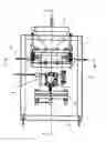
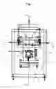


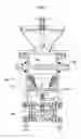
Sources:
- United States Patent and Trademark Office - verify current appl. status at the USPTO↗
Recent applications in this class:
- » 20240001510 2024-01-04
METHOD AND APPARATUS WITH VENTING OR EXTRACTION OF TRANSPORT FLUID FROM BLAST STREAM - » 20230226555 2023-07-20
Method of comminuting particles - » 20220281073 2022-09-08
Atmospheric pressure venturi intermix regulator cartridge and emission conduit - » 20170165810 2017-06-15
Method and apparatus for monitoring particle laden pneumatic abrasive flow in an abrasive fluid jet cutting system - » 20170106500 2017-04-20
Blast media comminutor - » 20160059385 2016-03-03
Blast treatment device and blast treatment method - » 20150101143 2015-04-16
Dry cleaning casing, dry cleaning apparatus and attachment method of screen plate - » 20140367479 2014-12-18
COcomposite spray method and apparatus - » 20120264355 2012-10-18
POLISHING METHOD BY BLASTING AND NOZZLE STRUCTURE FOR A BLASTING APPARATUS FOR USE IN THE POLISHING METHOD - » 20120064806 2012-03-15
System for dispensing abrasives into a gas stream for cleaning pipe interiors