Summing comparator for higher order class D amplifiers
US20070024366A1
2007-02-01
11/389,709
2006-03-27
✅ Patent granted
US 7,498,879 B2
2009-03-03
-
-
Patricia Nguyen
2026-04-23
Abstract:
The summing comparator includes: a first integrator; a second integrator for receiving an output of the first integrator; and a comparator for switching when the output of the first integrator is greater than the output of the second integrator. The outputs of the first and second integrators are directly compared by the comparator without the necessity of a summing amplifier.
Inventors:
- Gangadhar Burra 13 🇺🇸 Plano, TX, United States
- Jagadeesh Krishnan 6 🇺🇸 Dallas, TX, United States
- Srinath M. Ramaswamy 2 🇺🇸 Dallas, TX, United States
Assignee:
- TEXAS INSTRUMENTS INCORPORATED 18,931 🇺🇸 Dallas, TX, United States
Interested in similar patents?
Get notified when new applications in this technology area are published.
Classification:
H03F1/30 » CPC further
Details of amplifiers with only discharge tubes, only semiconductor devices or only unspecified devices as amplifying elements Modifications of amplifiers to reduce influence of variations of temperature or supply voltage or other physical parameters
H03F1/34 » CPC further
Details of amplifiers with only discharge tubes, only semiconductor devices or only unspecified devices as amplifying elements Negative-feedback-circuit arrangements with or without positive feedback
H03F3/2173 » CPC further
Amplifiers with only discharge tubes or only semiconductor devices as amplifying elements; Power amplifiers, e.g. Class B amplifiers, Class C amplifiers with semiconductor devices only; Class D power amplifiers; Switching amplifiers of the bridge type
H03F2200/261 » CPC further
Indexing scheme relating to amplifiers Amplifier which being suitable for instrumentation applications
H03F2200/331 » CPC further
Indexing scheme relating to amplifiers Sigma delta modulation being used in an amplifying circuit
H03F2200/351 » CPC further
Indexing scheme relating to amplifiers Pulse width modulation being used in an amplifying circuit
H03F3/217 » CPC main
Amplifiers with only discharge tubes or only semiconductor devices as amplifying elements; Power amplifiers, e.g. Class B amplifiers, Class C amplifiers with semiconductor devices only Class D power amplifiers; Switching amplifiers
Description
CROSS REFERENCE TO RELATED APPLICATIONSSer. No. 11/193,867 filed Jul. 29, 2005, entitled “Class-D Amplifier System”.
FIELD OF THE INVENTIONThe present invention relates to electronic circuits, and more specifically, to a summing comparator for higher order class D amplifiers.
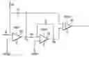
BACKGROUND OF THE INVENTION FIG. 1 shows a standard prior art implementation of a summing comparator. The device of FIG. 1 includes integrators 20 and 22; summing amplifier 24; comparator 26; resistors RI, RF, RZ; capacitors CI and CZ; DC reference voltage 28; common mode voltages VCM1 and VCM2; integrator 20 output Vp; integrator 22 output Vm; and source voltage nodes VDDA and GND. The outputs of integrators 20 and 22 are summed using a buffer or some kind of an instrumentation amplifier (summing amplifier 24) and then the sum is compared to a DC reference voltage 28 or ground GND by comparator 26. As long as this output is greater than the DC reference voltage, the comparator 26 switches. The disadvantage with this method is that it needs summing amplifier 24. Such an implementation is area expensive and consumes more power. In the implementation shown in FIG. 8, the comparator switches when
V
p
>
V
m
⇒
(
-
K
s
-
K
2
s
2
)
>
0
⇒
-
K
s
>
K
2
s
2
Where
-
K
s
represents the output of integrator 20 at node Vp,
K
2
s
2
represents the output of integrator 22 at node Vm,
-
K
s
-
K
2
s
2
represents the output of summing amplifier 24, and the DC reference voltage is ground.
A summing comparator includes: a first integrator; a second integrator for receiving an output of the first integrator; and a comparator for switching when the output of the first integrator is greater than the output of the second integrator. The outputs of the first and second integrators are directly compared by the comparator without the necessity of a summing amplifier.
BRIEF DESCRIPTION OF THE DRAWINGSIn the drawings:
FIG. 1 is a circuit diagram of a standard prior art implementation of a summing comparator;
FIG. 2 is a circuit diagram of a preferred embodiment summing comparator, according to the present invention.
DETAILED DESCRIPTION OF PREFERRED EMBODIMENTS In the preferred embodiment summing comparator, shown in FIG. 2, the summing amplifier 24 and comparator 26 of the prior art device, shown in FIG. 1, are replaced by comparator 30. The output of integrator 20 and the output of integrator 22 are directly compared by comparator 30 without the necessity of a summing amplifier. The equation below shows that the preferred embodiment implementation shown in FIG. 2 is mathematically and electrically similar to the prior art invention of FIG. 1, with the additional advantage of being a low-area and low power solution.
V
p
>
V
m
⇒
-
K
s
>
K
2
s
2
⇒
(
-
K
s
-
K
2
s
2
)
>
0
Where
-
K
s
represents the output of integrator 20 at node Vp,
K
2
s
2
represents the output of integrator 22 at node Vm.
While this invention has been described with reference to an illustrative embodiment, this description is not intended to be construed in a limiting sense. Various modifications and combinations of the illustrative embodiment, as well as other embodiments of the invention, will be apparent to persons skilled in the art upon reference to the description. It is therefore intended that the appended claims encompass any such modifications or embodiments.
Claims
What is claimed is:1. A circuit comprising:
a first integrator;
a second integrator coupled to an output of the first integrator; and
a comparator having a first input coupled to the output of the first integrator and a second input coupled to an output of the second integrator.
2. The circuit of claim 1 wherein the comparator switches when the output of the first integrator is greater than the output of the second integrator.
3. A circuit comprising:
a first integrator;
a second integrator for receiving an output of the first integrator; and
a switching device for switching when the output of the first integrator is greater than the output of the second integrator.
4. The circuit of claim 3 wherein the switching device is a comparator.
5. A method for performing a summing comparator function comprising:
integrating an input signal and providing a first integrated output signal;
integrating the first integrated output signal and providing a second integrated output signal; and
comparing the first integrated output signal with the second integrated output signal.
6. The method of claim 5 wherein the step of comparing determines if the first integrated output signal is greater than the second integrated output signal.
Images & Drawings included:


Sources:
- United States Patent and Trademark Office - verify current appl. status at the USPTO↗
Recent applications in this class:
- » 20250253812 2025-08-07
LOW VOLTAGE FOR AUDIO CIRCUITS, DEVICES AND METHODS - » 20250233562 2025-07-17
CLASS-D AUDIO AMPLIFIER - » 20250202444 2025-06-19
AUTO-CALIBRATION DRIVING STRENGTH SYSTEM FOR CLASS-D AMPLIFIER - » 20250167740 2025-05-22
CLASS D AMPLIFIER CAPABLE OF ANTI-CLIPPING - » 20250141412 2025-05-01
METHODS AND APPARATUS TO MODULATE SIGNALS USING MULTI-CLASS MODULATION CIRCUITRY - » 20250119110 2025-04-10
MODULATOR INTEGRATED CIRCUIT PACKAGE - » 20250112600 2025-04-03
POWER-ON AND SHUT-DOWN POP REDUCTION IN AUDIO SYSTEMS - » 20250096750 2025-03-20
VOLTAGE-TO-TIME-TO-VOLTAGE AMPLIFIER (VTVA) USING TIME DELAY - » 20240267007 2024-08-08
CLASS D AMPLIFICATION CIRCUIT - » 20240162867 2024-05-16
CLASS-D AMPLIFIER ABLE TO REDUCE POWER NOISE
Recent applications for this Assignee:
- » 20250291595 2025-09-18
CIRCUIT, SYSTEM, AND METHOD FOR MATRIX DECIMATION - » 20250286550 2025-09-11
TRANSISTOR SHUTDOWN CIRCUT - » 20250279725 2025-09-04
CONDUCTION MODE CONTROL - » 20250274138 2025-08-28
SWITCH REGULATOR - » 20250267687 2025-08-21
ENHANCED BROADCAST TRANSMISSION IN UNSLOTTED CHANNEL HOPPING MEDIUM ACCESS CONTROL - » 20250266825 2025-08-21
BOOTSTRAP CIRCUIT - » 20250247097 2025-07-31
LEVEL SHIFTER CIRCUIT - » 20250247082 2025-07-31
LOW AREA AND POWER MULTI-BIT FLIP-FLOP - » 20250246995 2025-07-31
SWITCHING CONVERTER DEADTIME CONTROL - » 20250246345 2025-07-31
TRIMMING RESISTOR USING MODULATED SIGNAL