Light intensity sensor for optical fibers
US20070034780A1
2007-02-15
11/500,016
2006-08-07
Abstract:
A light intensity sensor includes photodiode or other light sensitive device, and a capacitor connected to the photodiode. A microcontroller measures the time interval required for the capacitor to reach a predetermined voltage level. The current produced by the photodiode as a function of the light intensity is known, such that the time interval can be used to determine the light intensity. The microcontroller is configured to reset the capacitor voltage to zero after the predetermined voltage level is reached, and the measuring process is repeated.
Interested in similar patents?
Get notified when new applications in this technology area are published.
Classification:
G01M11/30 » CPC main
Testing of optical apparatus; Testing structures by optical methods not otherwise provided for Testing of optical devices, constituted by fibre optics or optical waveguides
H01J40/14 IPC
Photoelectric discharge tubes not involving the ionisation of a gas; Details Circuit arrangements not adapted to a particular application of the tube and not otherwise provided for
Description
CROSS-REFERENCE TO RELATED APPLICATIONSThis application claims the benefit of U.S. Provisional Application No. 60/706,075, filed Aug. 5, 2005, the entire contents of which is hereby incorporated by reference.
BACKGROUND OF THE INVENTIONFiber optic circuits generally include a transmitter such as a laser that converts an electrical signal (electrical energy) into a light signal (light energy) and injects the light into an optical fiber. A receiver coupled to the optical fiber converts the light energy into electrical energy after the light signal is transmitted through the optical fiber. A known circuit for converting light energy into electrical energy is known as a transimpedance amplifier (FIG. 3).
A photodiode D1 is a transducer that converts light energy into an electrical current Id. The amount of current is, to a first approximation, linearly proportional to the amount of light energy seen by the diode. This current is generally very small, no more than a few microamps. In order to magnify this current into a quantity usable by digital electronics, the transimpedance amplifier produces a voltage that is proportional to the current Id and is a much larger, more usable quantity.
For the prior art circuit of FIG. 3, it can be shown that with ideal components, the voltage at the node labeled Vout is given by the equation:
Vout=(R1+R2)Id
By choosing large resistors R1 and R2 (typically in the mega-ohm range), the output voltage can be on the order of volts even though the photodiode current is on the order of microamps. The operational amplifier U1 in the circuit of FIG. 3 is necessary so that digital components that attempt to measure the voltage Vout do not disturb the operation of the circuit. The prior art circuit of FIG. 3 is typically utilized in fiber optic communications systems requiring virtually instant sensing of light intensity.
The transimpedance amplifier circuit of FIG. 3 has several disadvantages. First, the circuit of FIG. 3 is highly sensitive to variations in photodiode current that may be caused by variations of temperature or physical mounting and coupling. Over a temperature range of −40° C. to +100° C., an Optek OP999 photodiode (for example) exhibits a variation of anywhere from one one-thousandth ( 1/1000) to 1000 times the “dark current” (current Id when no light shines on the photodiode) at +25° C. With fixed resistors R1 and R2, the output voltage Vout will vary greatly with temperature. Additional circuitry may be required to compensate for the inflexibility of R1 and R2 and thus compensate for the large variations in current. In use, the photodiode is mechanically coupled to an optical fiber. Variations in the quality of the coupling leads to variations in the amount of light incident upon the photodiode from one assembly to another. Also, the operational amplifier U1 adds to the system cost and increases circuit board area. Finally, the analog output voltage VOU, requires that the external digital circuitry contain an analog-to-digital converter (A/D) in order to make use of this voltage in a digital control algorithm, potentially increasing system cost. Due to the large variations in expected current it is generally not sufficient to simply use a comparator instead of an A/D converter as the trip-point of the comparator would have to adapt to the variations in current.
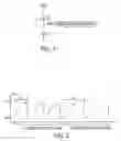
BRIEF DESCRIPTION OF THE DRAWINGSFIG. 1 is a circuit according to one aspect of the present invention;
FIG. 2 is a graph of the time-domain behavior of the circuit of FIG. 1;
FIG. 3 is a prior art circuit; and
FIG. 4 is another circuit.
DETAILED DESCRIPTION OF PREFERRED EMBODIMENTThe present application is related to U.S. patent application Ser. No. ______, entitled TEMPERATURE SENSING CIRCUIT, filed on even date herewith using Express Mail No. EV592299131US, the entire contents of which are incorporated by reference.
For purposes of description herein, the terms “upper,” “lower,” “right,” “left,” “rear,” “front,” “vertical,” “horizontal,” and derivatives thereof shall relate to the invention as oriented in FIG. 1. However, it is to be understood that the invention may assume various alternative orientations and step sequences, except where expressly specified to the contrary. It is also to be understood that the specific devices and processes illustrated in the attached drawings and described in the following specification are simply exemplary embodiments of the inventive concepts defined in the appended claims. Hence, specific dimensions and other physical characteristics relating to the embodiments disclosed herein are not to be considered as limiting, unless the claims expressly state otherwise.
An electronic circuit according to the present invention (FIG. 1) detects changes in the intensity of light in an optical fiber. The circuit may be utilized to detect changes in light intensity that are the result of pressure applied at a point along the length of an optical fiber. An example of an optical fiber pressure sensor that utilizes changes in light intensity to sense pressure is disclosed in U.S. Pat. No. 6,912,912, issued on Jul. 5, 2005, the entire contents of which are incorporated by reference. The circuit of FIG. 1 includes a photodiode, a capacitor, and a microcontroller. Additional circuitry and wiring (not shown) of a known type may be utilized to provide for proper operation of the microcontroller.
The capacitor C1 is initially discharged such that the potential at node Vout is 0V (or “ground”). The photodiode D1 converts light energy into an electrical current Id. The current charges the capacitor C1 and increases the voltage at the node Vout. The microcontroller senses this voltage and measures the length of time required for the voltage to reach a predetermined voltage level VT. This time is a function of the light level, and therefore provides a measurement of the light energy. The longer it takes for Vout to reach the specified voltage level VT, the lower the light energy.
After the microcontroller has detected that Vout has reached VT, the microcontroller then discharges the capacitor C1 using the same pin that was used for sensing Vout. That is, the pin changes direction from being an input signal to the microcontroller to become an output signal that is set to 0 volts. The effect of this action is to set Vout to 0 and allow for another capacitor charging process to begin. In this fashion, consecutive repeated measurements are taken.
To detect pressure applied at a point along the length of an optical fiber, the time it takes for Vout to reach VT is initially measured, averaged, and stored in the microcontroller memory. After this initial set-point calibration is complete, consecutive repeated measurements are taken as described above. If the time it takes Vout to reach VT exceeds the initial measurement by some specified amount, the application of pressure is detected and reported.
The time-domain behavior of the circuit is illustrated in FIG. 2. At the nominal (“Normal”) light intensity level, the capacitor voltage Vout takes t0 seconds to charge from 0 volts to VT volts. After this time, the microcontroller forces the signal Vout to 0 volts. After a short duration during which the capacitor C1 is allowed to discharge, the microcontroller stops forcing the voltage at Vout to 0 volts and allows the photodiode to charge the capacitor C1 again. When the light intensity is reduced, the capacitor C1 charges more slowly (due to the reduced current Id) and it now takes t1 seconds to charge the capacitor C1 from 0 volts to VT volts. The microcontroller detects this change in time and reports the reduction of light intensity. Although the circuit of FIG. 4 is believed to be novel, it is not as flexible as the circuit of FIG. 1 for those reasons described in more detail above.
FIG. 4 shows another prior art circuit. Even though the circuit of FIG. 4 may appear to generate a voltage Vout=R3Id that can be made large enough to be usable, an attempt to connect the node Vout to an actual digital device typically renders the circuit unusable. This is because the leakage currents of digital devices are large relative to the photodiode current.
It will be readily apparent to those skilled in the art that other variations of the light intensity circuits just described may be utilized. For example, other light-sensitive devices such as a phototransistor may be utilized in place of the photodiode. Also, the microcontroller may comprise circuit elements configured to provide the functions of the microcontroller.
The circuit of the present invention provides several benefits. First, no operational amplifier is necessary. The circuit according to the present invention can be described as converting current to time. The lower the current, the longer the time it takes to charge the capacitor C1 to a specified voltage level. Varying conditions of temperature, fiber mechanical coupling, etc. will only lead to variations in this time interval and do not require any change to or adaptation of the fixed circuit components (photodiode and capacitor). Variations in the time interval can be compensated in the microcontroller software. Also, the microcontroller does not need to have an A/D converter. The microcontroller will generally have a built-in analog comparator, but a full-fledged A/D converter is not required. Thus, a wider range of microcontrollers may be utilized. Finally, the microcontroller may not need to have a comparator. A digital input pin of the microcontroller may be used as a rudimentary comparator. Because digital inputs recognize only one of two states, logic low and logic high, some voltage threshold exists within the microcontroller which serves as the specified required voltage level for Vout.
In the foregoing description, it will be readily appreciated by those skilled in the art that modifications may be made to the invention without departing from the concepts disclosed herein. Such modifications are to be considered as included in the following claims, unless these claims by their language expressly state otherwise.
Claims
The invention claimed is:1. A light intensity sensor, comprising:
an electrical power source;
a photodiode connected to the power source and defining a voltage at a node opposite the electrical power source, the photodiode providing an electrical current that varies a result of an intensity of light incident on the photodiode;
a capacitor connected to the photodiode; and
a controller configured to measure the length of time for the voltage to go from a first predetermined value to a second predetermined value and thereby determine the intensity of light incident on the photodiode.
2. The light intensity sensor of claim 1, wherein:
the controller comprises a microcontroller.
3. The light intensity sensor of claim 1, wherein:
the controller discharges the capacitor after the voltage reaches the second predetermined value and thereby set the voltage at the first predetermined value.
4. The light intensity sensor of claim 1, wherein:
the first predetermined voltage is ground.
5. The light intensity sensor of claim 1, wherein:
the sensor generates a signal if the length of time for the voltage to go from the first predetermined value to the second predetermined value is greater than a specified length of time.
Images & Drawings included:


Sources:
- United States Patent and Trademark Office - verify current appl. status at the USPTO↗
Similar patent applications:
Recent applications in this class:
- » 20250164348 2025-05-22
WINDSHIELD DISPLAY AND TESTING SYSTEM - » 20250146902 2025-05-08
OBLIQUE LIGHTING SYSTEM FOR INSPECTION OF END CONNECTORS OF FIBER OPTIC CABLES BY MICROSCOPE - » 20250123180 2025-04-17
JOINT FIBER MONITORING - » 20250102398 2025-03-27
METHOD TO DETERMINE LINE ANGLE AND ROTATION OF MULTIPLE PATTERNING - » 20240410784 2024-12-12
OPTICAL TEST DEVICE AND CONNECTOR ADAPTER - » 20240402041 2024-12-05
CHANGEABLE TIP FOR OPTICAL FIBER INSPECTION DEVICE - » 20240385077 2024-11-21
OBJECTIVE LENS ARRANGEMENT, MEASURING DEVICE AND METHOD FOR MEASURING OF A NEAR EYE DISPLAY - » 20240385076 2024-11-21
Visual Fault Locator (VFL) with variable gain control - » 20240310243 2024-09-19
INTERFEROGRAM PHASE ESTIMATION METHOD - » 20240310242 2024-09-19
Bidirectional Optical Power Monitor