Device for depositing sheets for a printing machine
US20070045950A1
2007-03-01
11/508,634
2006-08-23
Abstract:
A device for depositing sheets for a printing machine. The invention provides a device, which, while safely guiding sheets, is, at the same time, relatively complex and can still be configured in a largely open and accessible manner. The device is characterized by a transport path segment for the sheets, the path branching in the region of influence of a rotating transport member, whereby the transport member itself forms a part of the boundary of the transport path segment, and whereby an adjustable switch is provided in the branching region. The switch is used to enable a path for a sheet transported through the transport path segment in transport direction after a part of the transport path segment bordered by the transport member in order for the sheet to leave the region of influence of the rotating transport member, or to enable a path for a guiding deflection by the transport member acting as the deflecting member.
Interested in similar patents?
Get notified when new applications in this technology area are published.
Classification:
G03G15/6552 » CPC main
Apparatus for electrographic processes using a charge pattern; Apparatus which relate to the handling of copy material Means for discharging uncollated sheet copy material, e.g. discharging rollers, exit trays
B65H39/10 IPC
Associating, collating, or gathering articles or webs Associating articles from a single source, to form, e.g. a writing-pad
Description
FIELD OF THE INVENTIONThe invention relates to a device for depositing sheets for a machine, which processes sheets graphically, in particular for a printing machine, preferably for an electrophotographically operating printing machine.
BACKGROUND OF THE INVENTIONBasically, such a device has been known from document DE 101 12 945 A1. Said device comprises a metal guide baffle which reliably feeds sheets to a stacking device. This known stacking device consists essentially of simple transport rolls, which only shifts the respective sheet onto the top side of the stack. More complex transport devices for sheets, in particular those comprising junctions, use something similar to transport channels or transport tunnels which are formed and bordered on both sides by metal guide baffles and thus are also largely closed to access. Transport rollers can locally extend through these metal guide baffles. Such a transport path configuration has been known, for example, from document GB 2 287 456 A. Thus, to permit access to this embodiment, for example when a material jam occurs, some of the sections of the metal guide baffles forming the walls of the transport paths are configured as flaps, which can be folded about hinges.
As opposed to this, the object of the invention is to provide a device of the aforementioned type, which, while safely guiding sheets, is, at the same time, relatively complex and can still be configured in a largely open and accessible manner.
In accordance with the invention, this object is achieved by a device which is characterized by a transport path segment for the sheets, said path branching in the region of influence of a rotating transport member, whereby said transport member itself forms a part of the boundary of the transport path segment, and whereby an adjustable switch is provided in the branching region, said switch being used to enable a path for a sheet transported through the transport path segment in transport direction after a part of the transport path segment bordered by the transport member in order for said sheet to leave the region of influence of the rotating transport member, or to enable a path for a guiding deflection by the transport member acting as the deflecting member.
In accordance with the invention, a switch and a junction of the transport path are located in the close proximity and region of influence of a rotating deflecting member, so that, advantageously, this transport member can act as a distribution turn table, said transport member forming, in this region, as a function of the branch selected by the switch, a boundary of the transport path over a larger or smaller circumferential segment and carrying along the respective sheet, said region being at the same time relatively openly accessible for intervention with a potential material jam. This inventive embodiment can also be combined with a rotating depositing system, in that at least one rotating deflecting member is provided, as has been known, for example, from document DE 103 09 095 B3.
SUMMARY OF THE INVENTIONIn accordance with the invention, in particular, branches may be provided, whereby one branch, for leaving the region of influence of the rotating transport member, leads to a single-sheet deposit means, and the other branch, for a guiding deflection performed by the transport member, leads to a stacker.
In order to prevent the switch from ever impeding the sheet's travel, the free end of said switch can be retracted, this being achieved in a particularly preferred embodiment in that the switch meshes in its respective position with guide elements for the sheet.
For example, the switch can be thrown by means of an electromagnet, for example, with the use of a plunger, in which case the switch adjustment can be integrated in a control means, which, by means of data relating to the sheet sequence, will automatically perform the correct switch adjustment.
The majority of the elements of the inventive device, this also referring to the transport member, can be configured as cost-effective and sturdy injection-molded components.
Another modification of the invention provides that the outer circumference of the transport member be provided with a coating, which exhibits a desired grip for the transport of sheets owing to a defined Shore hardness and which, due to sufficient recovery from deformation, excludes a permanent deformation. Specifically, a silicon material may be chosen for the coating. In order to allow the problem-free transport of even longer and/or stiffer sheets, the invention preferably provides that the transport member have a diameter greater than or equal to 200 millimeters. Thinner sheets are also automatically stiffened due to the cross-track deflection, i.e., parallel to the axis of the transport member.
Yet another modification of the invention provides that, on one of the branch paths, the transport member is followed by another rotating transport member preferably having essentially the same size, and that the sheets are routed in an essentially S-shaped path around these transport members, in which case, for example, said second transport member could be configured as a stacking wheel of a rotating stacking system.
The transport path segment leading away from the transport member could be configured, instead of as a single-sheet deposit means, specifically also as a transport path connection for another machine that is subsequently to be docked thereto. For example, in this case, a printing machine could be connected with a device for further processing, for example a varnishing unit or a folding and binding device. Specifically, in accordance with the invention, the machine equipped with the inventive device, can comprise an open or variable end. Thus, instead of a down-stream machine, one or more modules of the machine itself may be provided there, so that the thusly equipped machine can advantageously be designed in a modular manner in this end region.
In accordance with yet another embodiment, the invention also provides that the inventive device be configured as a module, thus permitting the direct successive connection of several of said essentially similarly configured modules in order to create a multi-branch transport path or their indirect connection by interposing and incorporating additional modules.
BRIEF DESCRIPTION OF THE DRAWINGSAn embodiment of an inventive device, which could result in additional inventive features, which, however, does not restrict the scope of the invention, is shown by schematic drawings. They are show in:
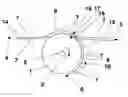
FIG. 1 is a kind of side or sectional view of elements of the inventive device;
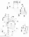
FIG. 2 is a plan view of a drive roller projecting from a recess;
FIG. 3 is a side or sectional view of the region of an adjustable switch; and,
FIG. 4 is the switch as in FIG. 3, in plan view.
DETAILED DESCRIPTION OF THE INVENTIONThe central element of the inventive device is a driven transport member 1, which rotates in the direction of an arrow 2 and is driven by a motor via a shaft 3. Two smaller transport or guide rollers 7, which are indicated only schematically in dashed lines to avoid confusion, may be provided alongside a sheet transport path for the transport of sheets in the direction indicated by arrows 4, 5, 6, and, if required, can be coupled directly or indirectly with the drive of transport member 1. For this kind of design, however, it is important that the proper transmission ratio between the different elements be taken into account. Otherwise, different circumferential velocities occur between transport rollers, guide rollers and drive rollers 7 of a straight transport path segment 1, 5 and transport member 1, so that, ultimately, the respective sheet will be pulled or slowed down too much and a wave is formed in the sheet.
Transport member 1 preferably consists of a core body (e.g., an injection-molded component), the circumference of which is coated with a grip coating. This may be, for example, a silicon coating having a defined Shore hardness and displaying a defined residual recovery from deformation. The Shore hardness indirectly defines the grip with respect to the sheet; the residual recovery from deformation ensures that the transport surface is not permanently deformed. Preferably, this applied surfacing is ground following the casting process, because, without a ground surface, certain types of sheets could adhere to transport member 1. It is also possible to use other materials; however, silicon material exhibits the best properties with respect to external influences. Such external influences, e.g., ozone and oils, are both being produced by the printing process of a printing machine.
In relation to the width of the sheet, transport member 1 is preferably located in the center of transport path 4, 5, 6, so that any sheet format can be symmetrically or centrally grasped and transported by transport member 1.
In a preferred embodiment, the outside diameter of transport member 1 is approximately 200 mm. This outside diameter is a function of the stiffness and the sheet material's thickness or weight per unit area. Very thin sheets can also be deflected by smaller diameters, without producing great stress. However, it is by all means possible that sheets having a sheet weight of 350 grams per square meter and a very high intrinsic stiffness in transport direction are used in a printing machine. Considering these sheets, a minimum diameter of 180 millimeters should be used. Otherwise, the sheets tend to become stuck in regions of directional change, i.e., there is no longer sufficient grip provided by the drive systems to transport the sheet through this path segment. In addition, freshly printed sheets that have been provided with fused toner of an electrophotographically operating printing machine tend to maintain embossed shapes. In this case, the sheet could retain its curved shape when it is advanced with a smaller deflecting diameter in the transport direction, said shape being visible when the sheet is deposited on a stack. Further processing of these sheets would then no longer be so easily possible.
Transport member 1 itself forms one side of transport path 6 along a segment of the path. This side does not use an additional metal guide baffle or an extrusion-molded component braced across the entire path width.
It is only the side of the transport path opposite transport member 1 that has metal guide baffles 8, 9 or extrusion-molded components which prevent the respective sheet from continuing to move in a straight line. This “outer” guide path 8, 9 extends across the entire path width. In order to be able to optionally provide the sheet to be transported with a counter balance in the region of transport member 1, openings 11 (FIG. 2) may be provided in the outer guide path 8, 9, said openings accommodating, as further addressed above, individual pressure rollers, drive rollers, transport rollers or guide rollers 7. As a result of spring force, these rollers can potentially be pressed against transport member 1. Their direction of rotation is indicated by arrow 10 on one of these drive rollers 7, for example.
As opposed to transport member 1, said pressure rollers 7 can be made of a hard material having sliding qualities. Preferably, this transport member should consist of conductive material in order to minimize contact-related electric charges for the sheet to be transported. When these pressure rollers 7 are sticking, the hard surface, having sliding qualities, prevents damage to the surface of the sheet. In these circumstances, a material with more grip would act like a rubber eraser on the sheet surface. The cutouts or openings 11 in guide path 8, 9 for these pressure rollers 7 preferably are rectangular openings ending not in a blunt shape but in a V-shape 13 in transport direction 12 (FIG. 2). This V-shape 13 prevents the lead edge of the sheet from becoming stuck or damaged when passing through this region. Individual pressure rollers 7 must be placed at such a distance from each other that even the smallest sheet length is at all times in the engagement zone of two pressure rollers 7. Only this can assure that a sheet to be processed will not be twisted during the transport process.
Overall, the inventive device is advantageously shown to be a very open transport system. The sheet to be transported is visible to the operator at all times if the housing covers of the machine in which this device is installed are opened.
Very thin and instable sheets could give rise to the concern that the corners of the lead edge of the sheet could limply hang down the side of the transport member 1; however, this is remedied by the stiffening, which automatically occurs due to the deflecting radius because the sheet cannot be curved simultaneously in two directions. Generally, however, this problem occurs only when the sheet is fed on the upper tangential point of transport member 1 (approximately in the region of reference number 8), so that there is no lower sheet guide element other than the centrally located transport member 1. When the sheet arrives at the lower tangential point, the width of the sheet rests on the outer guide element 9. In regard to the feeding from the top, it is only important that the sheet has already been taken over from transport member 1, and that the lead edge area of the sheet has already been slightly curved by transport member 1, before said sheet area leaves the lower guide element of the region of straight input transport. Only in this way is it possible to prevent the two leading corners of the sheet from hanging down limply, thereby no longer allowing threading of the sheet in the deflecting radius without causing damage. Otherwise, buckling of the sheet would result.
The driving shaft 3 of transport member 1 is supported on both sides. In so doing, the presence of two (not illustrated) lateral walls due to the sheet metal construction is used. Otherwise, the support could also be achieved by a form of cantilever.
The transport path shown in FIG. 1 is branched into segments 4, 5 and 6. As already described, segment 6 representing the deflecting region of transport member 1 is bordered by transport member 1 and by outer metal guide baffles 8, 9. Drive rollers 7 located in this region act as rollers pressing against transport member 1. Each of the mostly straight transport path segments 4 and 5 is bordered on both sides by pairs of metal guide baffles 14 and 15, respectively. Drive rollers 7 located in these regions are provided in pairs of rollers.
The inventive device is capable of creating any deflecting segment; only the outer guide path 8, 9, 14, 15 must be adapted to the respective input means 4 and output means 5 and 6.
In addition to the deflecting path 6 around transport member 1, the illustrated transport path 4, 5, 6 comprises a central junction and output means 5, which, for example, could lead to a simple single-sheet deposit means. In order to be able to select the desired transport path branch, a controlled switch 16 is used, said switch being located in the region of transport member 1 and being pivotable (in the direction of a double arrow 19) about an axle 20 (FIGS. 3 and 4). When the central branch 5 is enabled, switch 16 can preferably abut against the outside diameter of transport member 1, or even pass by under said transport member 1, so that transport member 1 can reliably guide the sheet away into segment 5.
Switch 16 is controlled by means of a plunger (wire element) and a lifting magnet (element not shown). Switch 16 has a preferred home position regarding the main transport direction. This home position is automatically taken when no electricity is applied to the lifting magnet. This is ensured by a return spring in the lifting magnet. In the present embodiment, the center intermediate path 5 is only of secondary importance. Therefore, when no electricity is applied to the lifting magnet, switch 16 always resets itself into the upper position, in which said switch is retraced in outer metal guide baffle 8 in area 17 in a recess 18 (FIG. 3) which is not illustrated in detail, thus being unable to collide with the lead edge of the sheet and, at the same time, closing the central path segment 5.
FIG. 2, again in plan view and viewed from the underside, shows a drive roller 7 driven on a shaft 21 and retracting through an opening 11, in which case said opening could be provided in one of the metal guide baffles 8, 9, 14, 15. In FIG. 2, it is particularly obvious that the largely rectangular opening 11 tapers into a V-shape 13 in advance or transport direction 12.
FIG. 3 shows detailed side and sectional views of switch 16 and region 17, but in contrast to the illustration of FIG. 1, upside down.
Switch 16 can be pivoted about axle 20 and can about against the outer metal guide baffle 8 in order to block segment 5 and thus clear the deflecting path 6 around transport member 1. In order to have front tip 22 of switch 16 completely out of the way and to not provide any resistance or an obstacle to the sheet, a recess may be configured and provided at the appropriate location 17 of metal guide baffle 8 in such a manner, that tip 22 can be retracted completely into this recess 18. In the example of FIG. 3, however, a bent region 23, i.e., the ramp of recess 18 as it were, is provided with slits to allow the tip 22 of switch 16 to mesh with corresponding teeth 24, so that tip 22 disappears in the guide path in this manner. Similarly, tip 22 of switch 16 could be retractable in its other pivot position on transport member 1 in order to clear segment 5. For example, transport member 1 could comprise clamping tongues configured as sheet metal tabs, holding the lead edge of a detected sheet on transport member 1. This sheet metal tab could also have slits for the engagement of tip 22 of switch 16 which thus can move under the lead edge of the sheet, thereby pushing said sheet's lead edge out of the clamping condition by retaining said sheet's lead edge during the continued movement of transport member 1 and thus being able to transfer said sheet's lead edge into segment 5.
FIG. 4 is a plan view of switch 16 with its axle 20. Tip 22 of the switch has teeth 24. Corresponding to the width, arrangement and intermediate spaces of these teeth 24, region 24 of metal guide baffle 8 must have slits and intermediate strips for the teeth 24 to mesh therewith.
Switch 16 and metal guide baffle 8 are provided with slits or teeth, respectively, in such a manner that, for safety reasons, the retracted switch 16 meshes across its entire width in the lead edge area with the slits of metal guide baffle 8. This tooth arrangement, as already explained above, can be mirrored on both sides of transport segment 6, so that switch 16 can, in both its end positions during its pivoting motion 19, retract in a meshing manner into guide path elements, and the sheet being passed above can definitely not become stuck.
In order to drive transport member 1 and potentially additional drive rollers 7, the device may use a drive shaft system or a central transport belt system. In this latter event, the transport belt system would be placed, exactly like transport member 1, symmetrically in the center of the width of transport path 4, 5, 6.
In conclusion, it should be noted that the embodiment of the inventive device is clearly less confusing than the conventional systems and, in addition, is more cost-effective if, e.g., similar pressure roller cores 7 are used for the remaining transport path region of a machine. If, in addition, these are injection-molded components, costs are reduced in the best possible manner. The same is true of transport member 1. Also in this case, the core element selected may be a cost-effective injection-molded component.
To be able to remove a sheet in the event of a jam, a preferred solution provides a special software program, which, in the event of a jam, organizes a defined transport of the sheets out of deflecting region 6 of transport member 1. However, instead of this software solution, it is also possible to use a mechanical solution. In such a mechanical solution, a guide system, including grip and closing mechanism, could be used to pivot transport member 1 out of the transport position and away from metal guide baffles 8, 9, so that an operator can pull the affected sheets out of this region.
The invention has been described in detail with particular reference to certain preferred embodiments thereof, but it will be understood that variations and modifications can be effected within the spirit and scope of the invention.
Claims
What is claimed is:1. Device for depositing sheets for a printing machine, characterized by a transport path segment for the sheets, said path branching in the region of influence of a rotating transport member, whereby said transport member itself forms a part of the boundary of the transport path segment and whereby an adjustable switch is provided in the branching region, said switch being used to enable a path for a sheet transported through the transport path segment in transport direction after a part of the transport path segment bordered by the transport member, in order for said sheet to leave the region of influence of the rotating transport member or to enable a path for a guiding deflection by the transport member acting as the deflecting member.
2. Device as in claim 1, characterized in that the path, for leaving the region of influence of the rotating transport member, leads to a single-sheet deposit means, and the path, for a transport deflection performed by the transport member, leads to a stacker.
3. Device as in claim 1, characterized in that the switch meshes in its respective position with guide elements for the sheet.
4. Device as in claim 3, characterized in that the switch can be thrown by means of an electromagnet.
5. Device as in claim 1, characterized in that the transport member is configured as an injection-molded component.
6. Device as in claim 1, characterized in that the outer circumference of the transport member is provided with a coating, which exhibits a desired grip for the transport of sheets owing to a defined Shore hardness and which, due to sufficient recovery from deformation, excludes a permanent deformation.
7. Device as in claim 6, characterized in that a silicon material is chosen for the coating.
8. Device as in claim 1, characterized in that the transport member has a diameter greater than or equal to 200 millimeters.
9. Device as in claim 1, characterized in that, on one of the branch paths, the transport member is followed by another rotating transport member preferably having essentially the same size, and that the sheets are routed in an essentially S-shaped path around these transport members.
10. Device as in claim 9, characterized in that the transport path segment leading away from the transport member is configured as a transport path connection for another machine to be subsequently docked thereto.
11. Device as in claim 1, characterized in that the device is configured as a module, thus permitting the direct successive connection of several of said essentially similarly configured modules in order to create a multi-branch transport path.
Images & Drawings included:
Sources:
- United States Patent and Trademark Office - verify current appl. status at the USPTO↗
Similar patent applications:
- » 20130001872
DEVICE FOR DEPOSITING SHEETS FOR A PRINTING MACHINE
Recent applications in this class:
- » 20240427277 2024-12-26
Image Forming Apparatus Capable of Inserting Sheet Tray in One Direction and Discharging Printed Sheet in Opposite Direction - » 20240111238 2024-04-04
Image forming apparatus and sheet conveyance device - » 20230305475 2023-09-28
Discharge device and image forming apparatus - » 20230205124 2023-06-29
Image forming apparatus - » 20230109925 2023-04-13
Image forming apparatus capable of inserting sheet tray in one direction and discharging printed sheet in opposite direction - » 20230088254 2023-03-23
Image forming apparatus - » 20230042587 2023-02-09
Image forming apparatus - » 20230004114 2023-01-05
Image forming apparatus - » 20220244672 2022-08-04
Image forming apparatus having a top cover with an overhang portion - » 20220171319 2022-06-02
Image forming apparatus