Joystick
US20070051593A1
2007-03-08
11/532,489
2006-09-15
✅ Patent granted
US 7,601,924 B2
2009-10-13
-
-
Renee S Luebke | Lheiren Mae A Anglo
2028-02-26
Abstract:
An apparatus for the manual control of remote controlled objects in real or virtual spaces, more specifically a joystick, is equipped with two control mechanisms (8, 9), each of which allowing complementary manual navigation in the x and y direction, coupled with each other in such a manner as to additionally allow a movement of the control mechanisms (8, 9) in relation to each other in the z direction.
Inventors:
- Dervis Demirtas 1 🇳🇱 Delft, Netherlands
- Joeri Jouke Post 1 🇳🇱 Rotterdam, Netherlands
- Jennigje Dankelman 1 🇳🇱 Pijnacker, Netherlands
- Joeri Jonke Post 1 🇳🇱 Rotterdam, Netherlands
Assignee:
- TECHNISCHE UNIVERSITEIT DELFT 195 🇳🇱 Delft, Netherlands
Interested in similar patents?
Get notified when new applications in this technology area are published.
Classification:
G05G9/04 » CPC main
Manually-actuated control mechanisms provided with one single controlling member co-operating with two or more controlled members, e.g. selectively, simultaneously the controlling member being movable in different independent ways, movement in each individual way actuating one controlled member only in which movement in two or more ways can occur simultaneously
G05G9/047 » CPC further
Manually-actuated control mechanisms provided with one single controlling member co-operating with two or more controlled members, e.g. selectively, simultaneously the controlling member being movable in different independent ways, movement in each individual way actuating one controlled member only in which movement in two or more ways can occur simultaneously the controlling member being movable by hand about orthogonal axes, e.g. joysticks
H01H19/00 IPC
Switches operated by an operating part which is rotatable about a longitudinal axis thereof and which is acted upon directly by a solid body external to the switch, e.g. by a hand
H01H21/00 IPC
Switches operated by an operating part in the form of a pivotable member acted upon directly by a solid body, e.g. by a hand
Description
CROSS-REFERENCE TO RELATED APPLICATIONSThis application is a continuation application of Patent Cooperation Treaty (PCT) patent application Ser. No. PCT/NL2005/000172, entitled “JOYSTICK”, to Technische Universiteit Delft, filed on Mar. 9, 2005, and the specification and claims thereof are incorporated herein by reference.
This application claims priority to and the benefit of the filing of Netherlands Patent Application Serial No. 1025722, entitled “JOYSTICK”, filed on Mar. 15, 2004, and the specification and claims thereof are incorporated herein by reference.
BACKGROUND OF THE INVENTION1. Field of the Invention (Technical Field)
The invention relates to a joystick having more than two degrees of freedom, at least designed for movement in the x and y direction at right angles to a longitudinal axis thereof, and in a rotational direction around said longitudinal axis.
2. Description of Related Art
Such a joystick is known from the European patent specification EP-B-O 790 488.
The known joystick is moveable in the x and y direction as well as in a rotational direction around the axis of the joystick, and is used for controlling a helicopter.
To determine the movement of the joystick in the rotational direction it possesses a detector that uses light signals, and an identifiable mosaic pattern working together with these light signals, wherein the rotational movement of the joystick can be derived through the detection of said pattern. As already known, the movement in the x and y direction can be determined by using electromagnetic means.
In practice, there is a demand for an inexpensive joystick that can be used for the training of hand-eye coordination such as is relevant for endoscopic operations and virtual endoscopy.
To this end the U.S. patent application 2001/00209737 proposes a device in accordance with the preamble, which possesses a fourth degree of freedom in the direction of the longitudinal axis.
The device known from this publication is provided with a handle for manual operation.
From DE-A-19736086, a joystick according to the preamble is known, which comprises a first tubular member surrounded by a second tubular member, wherein the first tubular member is designed for movement in the x and y direction and wherein the second tubular member is designed for sliding along and rotating around the first tubular member.
DETAILED DESCRIPTION OF THE INVENTIONThe joystick according to the invention is characterized in that the first tubular member and the second tubular member are equipped with a sensor and an identification means suitable for detection by the sensor, respectively.
This joystick according to the invention is inexpensive, is accurate and effective and very reliable.
The identification means is preferably a grid.
Without limiting the appended claims, the invention will be further elucidated herein below by way of an exemplary embodiment of the joystick according to the invention, and with reference to the drawing.
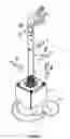
BRIEF DESCRIPTION OF THE SEVERAL VIEWS OF THE DRAWINGSIn the drawing, a single figure numbered 1 shows the joystick according to the invention.
This joystick 1 possesses more than two degrees of freedom, namely apart from the known degrees of freedom in the directions indicated with arrows x and y, also a degree of freedom in a rotational direction ω around a longitudinal axis 2 of the joystick 1. The joystick 1 according to the invention further possesses a fourth degree of freedom in the direction of said longitudinal axis 2, indicated with arrow z.
The joystick 1 according to the invention is provided with a handle 9 for manual operation, which is constructed such that the same possesses a first tubular member 3 and a second tubular member 4 surrounding said first tubular member 3.
In order to allow the joystick 1 according to the invention to fulfill its function, the first tubular member 3 is designed for movement in the x and y direction and the second tubular member 4 is designed for sliding along and rotating around the first tubular member 3.
In a manner well-known, the movement of the first tubular member 3 effected by operating the second tubular member 4 and the thus resulting movement in the x and y direction, can be detected and converted into electrical signals, which are conducted via a cable 5 to a computer 6 for further processing.
To detect the movement of the second tubular member 4 in the z-direction and in the rotational direction ω around the longitudinal axis 2 of the joystick 1, a sensor 7 may be provided that works together with an identification pattern, e.g. a grid pattern 8, which is detectable by the sensor 7. In the situation shown, the sensor 7 is to this end mounted on the first tubular member 3, while the grid 8 is provided on the second tubular member 4. Of course, the position of the two may conceivably also be interchanged. Via a cable 10, the obtained measuring signals are fed to the computer 6 for further processing.
Claims
What is claimed is:1. A joystick having more than two degrees of freedom, at least designed for movement in the x and y direction at right angles to a longitudinal axis thereof, and in a rotational direction ω around said longitudinal axis, and provided with a fourth degree of freedom in the direction of the longitudinal axis, and comprising:
a handle for manual operation, the handle comprising a first tubular member surrounded by a second tubular member; and
wherein the first tubular member is designed for movement in the x and y direction; and
wherein the second tubular member is designed for sliding along and rotating around the first tubular member, wherein the first tubular member and the second tubular member are equipped with a sensor and an identification means suitable for detection by the sensor.
2. A joystick according to claim 1, wherein the identification means comprises a grid.
Images & Drawings included:

Sources:
- United States Patent and Trademark Office - verify current appl. status at the USPTO↗
Similar patent applications:
- » 20170031382
Sealed joystick for the control of a machine, sealing element for that joystick and a control panel incorporating that joystick - » 20210341032
Work vehicle magnetorheological fluid joystick systems reducing unintended joystick motions - » 20130147494
Data input device with a potentiometer, and joystick intended for piloting an aircraft, said joystick comprising the data input device - » 20210340726
Work vehicle magnetorheological fluid joystick systems operable in modified joystick stiffness modes - » 20210340728
Work vehicle magnetorheological fluid joystick systems having adjustable joystick return positions - » 20250255761
JOYSTICK CONTROL SYSTEM AND A METHOD OF CONTROLLING A JOYSTICK - » 20060038776
Ultra thin optical joystick and personal portable device having ultra thin optical joystick - » 20080170036
Method of controlling a joystick and preventing the joystick from enabling unwanted events - » 10156332
Joystick device - » 9950216
Method and apparatus for testing a joystick control circuit
Recent applications in this class:
- » 20230077897 2023-03-16
Input device - » 20210365063 2021-11-25
Integrated driving control device - » 20160266602 2016-09-15
Vehicle operation system - » 20140373659 2014-12-25
Steering and brake control system for vehicles - » 20120273623 2012-11-01
Rotational aircraft throttle interface - » 20100206117 2010-08-19
Operator Control Device - » 20100206116 2010-08-19
Operator Control Device - » 20090303086 2009-12-10
Controller and electronic device using the same - » 20090302170 2009-12-10
Rotational aircraft throttle interface - » 20090062638 2009-03-05
Medical diagnostic device comprising an operating element for controlling system components
Recent applications for this Assignee:
- » 20250199148 2025-06-19
METHOD AND SYSTEM FOR TRANSCRANIAL ULTRASOUND IMAGING (TUI) - » 20250152124 2025-05-15
METHOD FOR ESTIMATING A MOVEMENT OF PARTICLES IN A BONE - » 20250150084 2025-05-08
BIAS VOLTAGE GENERATOR - » 20240401102 2024-12-05
PROTEIN AND PEPTIDE DATABASE-ENABLED RAPID MONITORING AND QUANTIFICATION OF MICROBES AND ASSOCIATED PRODUCTS - » 20240392763 2024-11-28
COMPLIANT CLOSED CELL UNIVERSAL JOINT - » 20240380086 2024-11-14
FUSED BUTTON BATTERY - » 20240229770 2024-07-11
Enhanced wake mixing for floating wind turbines - » 20240204180 2024-06-20
ANODE BASED ON HYDROGENATED AMORPHOUS SILICON CARBIDE FOR APPLICATION IN LITHIUM-ION BATTERIES - » 20240171123 2024-05-23
BALL-NET REFLECTOR FOR BIFACIAL FLOATING PHOTOVOLTAIC SYSTEMS - » 20240146503 2024-05-02
DIGITAL TRANSMITTER FEATURING A 50%-LO SIGNED PHASE MAPPER