Tank manifold assembly
US20070056643A1
2007-03-15
11/518,688
2006-09-11
✅ Patent granted
US 7,478,647 B2
2009-01-20
-
-
Kevin L Lee
2026-11-03
Abstract:
A tank manifold assembly for use in combination with fuel tanks of Hydrogen fuel cell-powered vehicles. The manifold assembly incorporates a regulator, an excess flow valve, a manual shutoff valve, and ports to receive separate components. The separate components may include, by way of example, a thermal relief valve, a pressure sensor, a pressure relief valve, a check valve, thermal temperature sensors, and a low pressure solenoid valve. The tank assembly is versatile and easily customized to particular applications.
Inventors:
- Todd W. Larsen 12 🇺🇸 Milaca, MN, United States
- Eric W. Neumann 4 🇺🇸 Princeton, MN, United States
Assignee:
- FISHER CONTROLS INTERNATIONAL LLC 126 🇺🇸 St. Louis, MO, United States
Interested in similar patents?
Get notified when new applications in this technology area are published.
Classification:
F16K1/305 » CPC main
Lift valves or globe valves , i.e. cut-off apparatus with closure members having at least a component of their opening and closing motion perpendicular to the closing faces specially adapted for pressure containers; Shut-off valves with additional means with valve member and actuator on the same side of the seat
F16K1/307 » CPC further
Lift valves or globe valves , i.e. cut-off apparatus with closure members having at least a component of their opening and closing motion perpendicular to the closing faces specially adapted for pressure containers Additional means used in combination with the main valve
F16K27/003 » CPC further
Construction of housing ; Use of materials therefor Housing formed from a plurality of the same valve elements
F17C2205/0146 » CPC further
Vessel construction, in particular mounting arrangements, attachments or identifications means; Mounting arrangements characterised by number of vessels; Two or more vessels characterised by the presence of fluid connection between vessels with details of the manifold
F17C2221/012 » CPC further
Handled fluid, in particular type of fluid; Pure fluids Hydrogen
F17C2250/043 » CPC further
Accessories; Control means; Indicating, measuring or monitoring of parameters; Indicating or measuring of parameters as input values; Parameters indicated or measured Pressure
F17C2250/0439 » CPC further
Accessories; Control means; Indicating, measuring or monitoring of parameters; Indicating or measuring of parameters as input values; Parameters indicated or measured Temperature
F17C2270/0184 » CPC further
Applications for fluid transport or storage on the road Fuel cells
H01M2250/20 » CPC further
Fuel cells for particular applications; Specific features of fuel cell system Fuel cells in motive systems, e.g. vehicle, ship, plane
Y02E60/32 » CPC further
Enabling technologies; Technologies with a potential or indirect contribution to GHG emissions mitigation; Hydrogen technology Hydrogen storage
Y02E60/32 » CPC further
Enabling technologies; Technologies with a potential or indirect contribution to GHG emissions mitigation; Hydrogen technology Hydrogen storage
Y02E60/50 » CPC further
Enabling technologies; Technologies with a potential or indirect contribution to GHG emissions mitigation; Hydrogen technology Fuel cells
Y02E60/50 » CPC further
Enabling technologies; Technologies with a potential or indirect contribution to GHG emissions mitigation; Hydrogen technology Fuel cells
Y02T90/40 » CPC further
Enabling technologies or technologies with a potential or indirect contribution to GHG emissions mitigation Application of hydrogen technology to transportation, e.g. using fuel cells
Y02T90/40 » CPC further
Enabling technologies or technologies with a potential or indirect contribution to GHG emissions mitigation Application of hydrogen technology to transportation, e.g. using fuel cells
Y10T137/7808 » CPC further
Fluid handling; Line condition change responsive valves; With separate connected fluid reactor surface; With opening bias [e.g., pressure regulator] Apertured reactor surface surrounds flow line
Y10T137/8085 » CPC further
Fluid handling; With means for separating solid material from the fluid Hollow strainer, fluid inlet and outlet perpendicular to each other
Y10T137/86831 » CPC further
Fluid handling; Systems; Multi-way valve unit Selective opening of plural ports
Y10T137/87917 » CPC further
Fluid handling; Systems Flow path with serial valves and/or closures
F16K11/07 IPC
Multiple-way valves, e.g. mixing valves; Pipe fittings incorporating such valves with all movable sealing faces moving as one unit comprising only sliding valves, i.e. sliding closure elements with linearly sliding closure members with cylindrical slides
Description
CROSS-REFERENCE TO RELATED APPLICATIONThis application is based on U.S. Provisional Patent Application Ser. No. 60/716,272, filed Sep. 12, 2005, the entirety of which is hereby incorporated by reference herein.
FIELD OF THE DISCLOSUREThis disclosure relates generally to controlling the flow of gas into and out of vessels for pressurized gas and, more specifically, to a customizable manifold assembly for use in controlling the flow of gas into and out of fuel tanks.
SUMMARYA tank manifold assembly of the present disclosure is provided with a fill port through which fluid, such as gas, may be introduced. An excess flow valve is also provided in the tank manifold assembly. The tank manifold assembly is engaged with a vessel, such as a tank, via a tank interface, such as an elongate externally threaded cylindrical interface portion, of the tank manifold assembly. The tank interface is received in a complementary opening in the tank, such as an internally threaded manifold receiving port located at a neck of the tank.
Gas flowing from the tank first passes through a replaceable filter of the tank manifold assembly, which filter is secured in position by an appropriate seal. The gas then flows through an excess flow valve of the tank manifold assembly. The excess flow valve provides an automatic shut-off feature, stopping the flow of gas in the event the rate of flow of the gas exceeds a predetermined trigger point.
A manual valve is disposed downstream of the excess flow valve. Provided the excess flow valve is open, permitting fluid flow to the manual valve, fluid is then introduced from the manual valve to a pressure reducing regulator. In order to protect low pressure system components, a pressure relief valve is disposed downstream of the pressure reducing regulator.
In one embodiment of the present disclosure, the tank manifold assembly is provided with a low pressure solenoid valve downstream of the pressure relief valve.
The tank manifold assembly is provided with a plurality of ports for receiving further components. Pressure sensors may be received in one or more pressure sensor receiving ports, so that pressure sensors may be provided on either the low pressure side or high pressure side of the tank manifold assembly. A temperature sensor port may be added to the high-pressure side of the manifold to facilitate monitoring the temperature of gas within the tank.
Additionally, a thermal relief port is provided in the tank manifold assembly, which communicates with a bore that extends axially along the tank interface portion of the tank manifold assembly. The thermal relief port will receive a thermal relief valve, which will release gas from the tank when temperature outside the tank exceeds a predetermined safe level.
The tank manifold assembly is disclosed in further detail with reference to the various drawing figures and the following detailed description of the preferred embodiments.
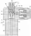
BRIEF DESCRIPTION OF THE SEVERAL VIEW OF THE DRAWINGFIG. 1 is a cross-sectional view, taken along lines A-A of FIG. 4, of a tank manifold assembly of the present disclosure;
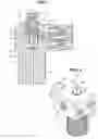
FIG. 2 is a perspective view of the tank manifold assembly shown in FIG. 1;
FIG. 3 is a perspective view from the direction of lines B-B of FIG. 2, of the tank manifold assembly shown in FIGS. 1 and 2;
FIG. 4 is a top view of the tank manifold assembly shown in FIGS. 1-3;
FIG. 5 is a cross-sectional view, similar to FIG. 1, showing a second embodiment of the tank manifold assembly installed on a fuel tank; and
FIG. 6 is a top view, shown partially in cross-section, of the tank manifold assembly shown in FIG. 5, with a low pressure solenoid valve provided downstream of a regulator of the tank manifold assembly.
DETAILED DESCRIPTION OF THE PREFERRED EMBODIMENTSAs shown in FIGS. 1-6, a tank manifold assembly 10 of the present disclosure includes a main body 12. The main body 12 includes a tank interface 14, such as in the form of an elongate, externally threaded cylindrical interface portion 16. The tank interface 14 is received in a complementary internally threaded manifold receiving port 18 located at a neck of a vessel, such as a fuel tank 20. An axially-extending bore 22 is provided in the main body 12. A filter 24 and filter seal 26 are provided in the bore 22, preferably in a location which facilitates removal and replacement of the filter 24 without having to remove the tank manifold assembly 10 from the tank 20.
The tank manifold assembly 10 is further provided with a fill port 28 (see FIG. 3), through which gas is introduced to the tank manifold assembly 10, a pressure reducing regulator 30, a thermal relief valve port 32, an excess flow valve 34, and downstream of the excess flow valve 34, a manual flow valve 36. Gas flows from the tank 20, through the replaceable filter 24, and into excess flow valve 34. The excess flow valve 34 includes an orifice 38 and a piston 40. The piston 40 of the excess flow valve 34 is normally biased (by a spring 42 having a predetermined stiffness) away from a valve seat 44. However, when fluid flow exceeds a predetermined trigger point, a pressure differential across the orifice 38 of the excess flow valve 34 provides the piston 40 with sufficient force to overcome the biasing load exerted by the spring 42, bringing the piston 40 into sealing engagement with the valve seat 44, thereby automatically shutting off the flow of fluid through the excess flow valve 34.
Various events may cause fluid flow to exceed the predetermined trigger point, such as a failure in the downstream side of the system, for instance due to a line burst or a major component failure. The automatic shut-off feature provided by the excess flow valve 34 therefore stops fluid flow from the tank 20 until the problem or event that caused of the excess flow is resolved. Once the problem is solved, the excess flow valve 34 may be reset manually by turning a valve stem 46 on the manual flow valve 36. Turning the valve stem 46 moves the piston 40 off the valve seat 44. Alternatively, the piston 40 of the excess flow valve 34 may automatically reset to a position in which it is biased away from the valve seat 44 by the spring 42.
Fluid is introduced from the manual flow valve 36 to the pressure reducing regulator 30. The manual flow valve 36 may be adjusted manually to shut off tank supply pressure to downstream system components. Upon such adjustment of the manual flow valve 36, a valve stem 46 travels down and seals against the piston 40 of the excess flow valve 34 to shut off the flow of gas or other fluid. The manual flow valve 36 reduces the number of components required in the tank manifold assembly 10, and minimizes overall size of the tank manifold assembly 10.
The pressure reducing regulator 30 is preset and non-adjustable. The pressure reducing regulator 30 serves to reduce inlet pressure to a predetermined outlet set point. The pressure reducing regulator 30 is provided with a positive shut-off feature. If a leak develops across a regulator valve seat 48, the outlet pressure rises above the predetermined outlet set point, applying additional force to the regulator valve seat 48 to reduce or stop gas leakage. In order to protect low pressure system components, a pressure relief valve port 50 is provided, into which a pressure relief valve (not shown) may be installed, downstream of the pressure reducing regulator 30.
Downstream of the pressure relief valve, a low pressure solenoid valve 52 may be provided. The tank manifold assembly 10 is also provided with a pressure sensor port 54 to receive an optional pressure sensor (not shown). Pressure sensors may be provided on either the low pressure side or the high pressure side of the tank manifold assembly 10. An additional port may be added to incorporate a temperature sensor to the high-pressure side of the tank manifold assembly 10 to facilitate monitoring the temperature of gas within the tank. The thermal relief valve port 32 will receive a thermal relief valve, which will release gas from the tank 20 when temperature outside the tank exceeds a predetermined safe level. A secondary bore 56 in the main body 12 is provided in fluid communication with the thermal relief valve port 32 and the interior of the tank 20, and extends axially along the tank interface 14. Tank pressure is routed via the secondary bore 56 to the thermal relief valve port 32.
In order to accommodate higher or lower fluid flow, various parameters of the tank manifold assembly 10 may be selected accordingly, such as the valve seat size and the valve components of the pressure reducing regulator 30 and/or the excess flow valve 34. The tank manifold assembly 10 of the present disclosure is particularly well suited for use in tanks of engines for hydrogen fuel cell powered vehicles. The tank manifold assembly 10 may also be used to control the flow of gases including, but not limited to, oxygen, hydrogen and nitrogen for a range of uses. The multiple ports within the main body 12 provide a highly customizable tank manifold assembly 10.
The tank manifold assembly 10 of the present disclosure operates to control tank pressures in a range from approximately 10 bar to approximately 700 bar Hydrogen, and the tank manifold assembly 10 operates in a temperature range from about −40° C. to 85° C.
Claims
We claim:1. A tank manifold assembly comprising:
a plurality of sensor ports, each of said sensor ports selectively receiving at least one of a group of a pressure sensor and a temperature sensor.
2. The tank manifold assembly of claim 1, wherein at least one of the sensor ports is disposed on a low pressure side of a main body of the tank manifold assembly.
3. The tank manifold assembly of claim 1, wherein at least one of the sensor ports is disposed on a high pressure side of the main body of the tank manifold assembly.
4. A tank manifold assembly comprising:
a main body including
a tank interface;
a fill port;
a filter in fluid communication with the fill port;
an excess flow valve downstream of the filter;
a manual flow valve downstream of the excess flow valve;
a pressure reducing regulator downstream of the manual flow valve;
a pressure relief valve downstream of the pressure reducing regulator; and
a plurality of sensor ports, each of said sensor ports selectively receiving at least one of a group of a pressure sensor and a temperature sensor.
5. The tank manifold assembly of claim 4, further comprising:
a low pressure solenoid valve downstream of the pressure relief valve.
6. The tank manifold assembly of claim 4, wherein at least one of the plurality of sensor ports is disposed on a low pressure side of the tank manifold assembly.
7. The tank manifold assembly of claim 4, wherein at least one of the plurality of sensor ports is disposed on a high pressure side of the tank manifold assembly.
8. The tank manifold assembly of claim 4, further comprising a thermal relief port in communication with the tank interface.
9. The tank manifold assembly of claim 8, further comprising a temperature sensor received in the thermal relief port.
10. A tank manifold assembly comprising:
a main body having:
a tank interface including an elongate, threaded cylindrical interface portion;
an axially-extending bore;
a fill port;
a replaceable filter received in the axially-extending bore, and in fluid communication with the fill port;
an excess flow valve downstream of the filter;
a manual flow valve downstream of the excess flow valve;
a pressure reducing regulator downstream of the manual flow valve;
a pressure relief valve downstream of the pressure reducing regulator; and
a plurality of sensor ports, each of said sensor ports selectively receiving at least one of a group of a pressure sensor and a temperature sensor.
11. The tank manifold assembly of claim 10, further comprising a filter seal disposed between the replaceable filter and the axially-extending bore.
12. The tank manifold assembly of claim 10, further comprising a thermal relief port in communication with the tank interface.
13. The tank manifold assembly of claim 12, further comprising a temperature sensor received in the thermal relief port.
14. The tank manifold assembly of claim 10, further comprising:
a low pressure solenoid valve downstream of the pressure relief valve.
15. The tank manifold assembly of claim 10, wherein at least one of the plurality of sensor ports is disposed on a low pressure side of the tank manifold assembly.
16. The tank manifold assembly of claim 10, wherein at least one of the plurality of sensor ports is disposed on a high pressure side of the tank manifold assembly.
17. The tank manifold assembly of claim 10, further comprising an excess flow valve including an orifice and a piston, the piston being normally biased away from a valve seat.
18. The tank manifold assembly of claim 10, wherein a spring of a predetermined stiffness provides the biasing force to normally bias the piston away from the valve seat.
Images & Drawings included:


Sources:
- United States Patent and Trademark Office - verify current appl. status at the USPTO↗
Similar patent applications:
Recent applications in this class:
- » 20250067346 2025-02-27
VALVE STRUCTURE FOR PROPANE TANK AND METHOD THEREOF - » 20250020218 2025-01-16
Valve Assembly, Pressure Vessel System, Vehicle, and Method for Discharging Fuel - » 20230220915 2023-07-13
Pressure maintaining gas cylinder valve - » 20220120348 2022-04-21
Valve structure for propane tank and method thereof - » 20220003323 2022-01-06
Safely release bleeder valve - » 20200332902 2020-10-22
Valve for controlling gas flow - » 20190249779 2019-08-15
Tank Valve - » 20190145527 2019-05-16
Main stop valve - » 20190032789 2019-01-31
Cylinder valve assembly with actuatable on-off control - » 20120118402 2012-05-17
GAS CYLINDER VALVE
Recent applications for this Assignee:
- » 20120181079 2012-07-19
Capacitor coupled cable shield feedthrough - » 20120167996 2012-07-05
Valve Controller Automatic Calibration Without User Interface - » 20120139725 2012-06-07
Automatic valve seating integrity test - » 20120043489 2012-02-23
Apparatus to bias valve closure members - » 20110042601 2011-02-24
Parabolic bonnet for three-way valve - » 20100319799 2010-12-23
Fluid pressure reduction devices - » 20100259461 2010-10-14
Antenna apparatus for explosive environments - » 20100084594 2010-04-08
Valves having removable internal actuation mechanisms - » 20100059131 2010-03-11
Noise level reduction of sparger assemblies - » 20100006159 2010-01-14
Pressure relief valves