Fuel cell
US20070072040A1
2007-03-29
11/528,818
2006-09-28
Abstract:
A fuel battery cell covered with a hydrophilic polymer layer.
Assignee:
- STMICROELECTRONICS SA 1,590 🇫🇷 Montrouge, France
Interested in similar patents?
Get notified when new applications in this technology area are published.
Classification:
H01M8/04171 » CPC main
Fuel cells; Manufacture thereof; Auxiliary arrangements, e.g. for control of pressure or for circulation of fluids; Arrangements for control of reactant parameters, e.g. pressure or concentration of gaseous reactants with simultaneous supply or evacuation of electrolyte; Humidifying or dehumidifying with product water removal using adsorbents, wicks or hydrophilic material
B82Y30/00 » CPC further
Nanotechnology for materials or surface science, e.g. nanocomposites
H01M8/04067 » CPC further
Fuel cells; Manufacture thereof; Auxiliary arrangements, e.g. for control of pressure or for circulation of fluids related to heat exchange Heat exchange or temperature measuring elements, thermal insulation, e.g. heat pipes, heat pumps, fins
H01M8/04291 » CPC further
Fuel cells; Manufacture thereof; Auxiliary arrangements, e.g. for control of pressure or for circulation of fluids Arrangements for managing water in solid electrolyte fuel cell systems
H01M8/1097 » CPC further
Fuel cells; Manufacture thereof; Fuel cells with solid electrolytes Fuel cells applied on a support, e.g. miniature fuel cells deposited on silica supports
H01M4/8657 » CPC further
Electrodes; Inert electrodes with catalytic activity, e.g. for fuel cells consisting of more than one material, e.g. consisting of composites layered
H01M2004/8689 » CPC further
Electrodes; Inert electrodes with catalytic activity, e.g. for fuel cells characterised by the polarity Positive electrodes
Y02E60/50 » CPC further
Enabling technologies; Technologies with a potential or indirect contribution to GHG emissions mitigation; Hydrogen technology Fuel cells
Y02E60/50 » CPC further
Enabling technologies; Technologies with a potential or indirect contribution to GHG emissions mitigation; Hydrogen technology Fuel cells
H01M8/04 IPC
Fuel cells; Manufacture thereof Auxiliary arrangements, e.g. for control of pressure or for circulation of fluids
H01M4/86 IPC
Electrodes Inert electrodes with catalytic activity, e.g. for fuel cells
Description
BACKGROUND OF THE INVENTION1. Field of the Invention
The present invention relates to a fuel cell.
2. Discussion of the Related Art
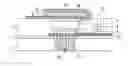
FIG. 1 shows an example of a fuel cell formed by microelectronic techniques. The cell is formed on a silicon wafer 1 coated with a first thin insulating layer 2 and with a second thicker insulating layer 3. An opening is formed in a portion of insulating layer 3. In this opening are successively deposited a support 4, a catalyst layer 5, an electrolyte 6, and a second catalyst layer 7. An electrode 10, placed on first insulating layer 2, enables taking a contact on the lower battery cell surface, on support 4. An opening 11 of second insulating layer 3 enables accessing to electrode 10. An upper electrode 12 enables taking a contact on upper catalyst layer 7. Electrodes 10 and 12 are provided with openings, and channels 13 are formed in silicon wafer 1 opposite to the openings in the lower surface metallization. Lower electrode 10 and upper electrode 12 respectively form an anode collector and a cathode collector.
Electrolyte 6 for example is a polymer acid such as Nafion in solid form and the catalyst layers for example are carbon- and platinum-based layers. This is an example of embodiment only. Various types of fuel cells that can be formed as illustrated in FIG. 1 are known in the art.
To operate the fuel cell, hydrogen is injected along arrow H2 on the lower surface side and air (carrying oxygen) is injected on the upper surface side. The hydrogen is “decomposed” at the level of catalyst layer 5 to form on the one hand H+protons which direct towards electrolyte 6 and on the other hand electrons which direct, by the outside of the cell, towards anode collector 10. The H+protons cross electrolyte 6 to reach catalyst layer 7 where they recombine with oxygen and electrons coming from the outside of the cell via the cathode collector. In a known fashion, with such a structure, a positive voltage is obtained on cathode collector 12 (on the oxygen side) and a negative voltage is obtained on anode collector 10 (on the hydrogen side).
A disadvantage of this type of fuel cell is that electrolyte 6 tends to desiccate along its use and the cell performances decrease.
SUMMARY OF THE INVENTIONAn object of the present invention is to provide a fuel cell comprising an electrolyte which does not desiccate.
An object of the present invention is to provide such a fuel cell of simple structure.
To achieve these and other objects, the present invention provides a fuel battery cell covered with a hydrophilic polymer layer.
According to an embodiment of the above-mentioned fuel battery cell, the hydrophilic polymer layer is placed close to a region of the cell where water is generated.
According to an embodiment of the above-described fuel battery cell, the hydrophilic polymer layer is porous or exhibits openings to enable passing of a gas such as oxygen.
According to an embodiment of the above-described fuel battery cell, a layer of a hydrophobic material covers the hydrophilic polymer layer.
According to an embodiment of the above-described fuel battery cell, the hydrophobic material layer is porous for this gas or exhibits at least one opening to enable passing of a gas such as oxygen.
According to an embodiment of the above-described fuel battery cell, the hydrophilic polymer layer is thermally conductive.
According to an embodiment of the above-described fuel battery cell, the hydrophilic polymer layer contains carbon nanotubes.
According to an embodiment of the above-described fuel battery cell, the layer of a hydrophobic material is thermally conductive.
According to an embodiment of the above-described fuel battery cell, the layer of a hydrophobic material is formed of carbon nanotubes.
According to an embodiment of the above-described fuel battery cell, the cell comprises an electrolyte placed between first and second catalyst layers placed between first and second catalyst layers respectively connected to an anode collector and to a cathode collector, hydrogen being brought to the rear surface of the cell at the level of the first catalyst layer, and oxygen being brought to the front surface of the cell at the level of the second catalyst layer, said hydrophilic polymer layer being placed at the front surface above the second catalyst layer and passing oxygen.
The foregoing and other objects, features, and advantages of the present invention will be discussed in detail in the following non-limiting description of specific embodiments in connection with the accompanying drawings.
BRIEF DESCRIPTION OF THE DRAWINGSFIG. 1 is a cross-section view of a known fuel battery cell;
FIG. 2 is a cross-section view of a fuel battery cell according to the present invention; and
FIG. 3 is a cross-section view of a fuel battery cell according to an alternative embodiment of the cell shown in FIG. 2.
DETAILED DESCRIPTIONFor clarity, the same elements have been designated with the same reference numerals in the different drawings and, further, as usual in the representation of integrated circuits, the various drawings are out of scale.
To avoid desiccation of a fuel battery cell, the present invention provides retaining the water naturally generated by the cell. Indeed, when the H+protons recombine with oxygen and electrons coming through the cathode collector, water forms at the level of upper catalyst layer 7. To avoid that this water evaporates, the present invention provides placing a hydrophilic polymer layer close to upper catalyst layer 7. This hydrophilic polymer layer enables maintaining a damp environment in the cell, and especially at the level of electrolyte 6.
FIG. 2 is a cross-section view of a fuel cell which comprises all the elements of the cell shown in FIG. 1. According to an aspect of the present invention, a hydrophilic polymer layer 20 is placed above upper catalyst layer 7. Hydrophilic polymer layer 20 covers the portion of upper electrode 12 located above upper catalyst layer 7 as well as the portions of insulating layer 3 located close to catalyst layer 7. A portion of upper electrode 12 located above second insulating layer 3 is exposed to leave its access free. Similarly, opening 11 is left free to enable access to lower electrode 10.
Further, to enable passing of air, and especially of oxygen, towards upper catalyst 7, hydrophilic polymer layer 20 preferably is porous. An example of a porous hydrophilic polymer layer is for example formed of agglomerated polyethylene functionalized by hydroxyl groups. In the case where the polymer layer is not porous, through openings are formed therein to allow an oxygen flow.
Further, another way to limit the evaporation of the water generated by the battery cell is to “cool down” the cell, since the evaporation increases as the cell temperature increases. To ease the thermal dissipation of the heat generated by the fuel battery cell, a thermally-conductive hydrophilic polymer layer is thus preferably selected.
For this purpose, a hydrophilic polymer layer containing carbon nanotubes may be used. Carbon nanotubes being very good heat conductors, the presence of a small quantity thereof provides a very good heat dissipation.
FIG. 3 is a cross-section view of a fuel battery cell comprising the same elements as those of the cell shown in FIG. 2. This cell further comprises a layer of a hydrophobic material 30 covering hydrophilic polymer layer 20. Hydrophobic layer 30 enables further limiting the evaporation of the water generated by the fuel cell.
The hydrophobic material layer preferably is formed of a porous material, letting through oxygen. In the opposite case, an opening of hydrophobic polymer layer 30 should be provided above upper catalyst layer 7 to let the oxygen necessary to the fuel battery cell operation flow.
An example of a porous hydrophobic layer letting oxygen flow is a layer formed of carbon nanotubes. Such a layer further provides a very good thermal dissipation of the heat generated by the fuel battery cell.
Of course, the present invention is likely to have various, alterations, improvements, and modifications which will readily occur to those skilled in the art. In particular, the previously-described drawings show a single fuel battery cell. In practice, on the same wafer 1, a large number of cells that may be assembled in series/parallel according to the desired use may be formed.
Further, the present invention applies to various types of fuel cells for which it is useful to retain the water that they generate.
Such alterations, modifications, and improvements are intended to be part of this disclosure, and are intended to be within the spirit and the scope of the present invention. Accordingly, the foregoing description is by way of example only and is not intended to be limiting. The present invention is limited only as defined in the following claims and the equivalents thereto.
Claims
What is claimed is:1. A fuel battery cell covered with a hydrophilic polymer layer.
2. The fuel battery cell of claim 1, generating water when used, the hydrophilic polymer layer being placed close to a region of the cell where water is generated.
3. The fuel battery cell of claim 1, wherein the hydrophilic polymer layer is porous or has openings to enable passing of a gas such as oxygen.
4. The fuel battery cell of claim 1, wherein a layer of a hydrophobic material covers the hydrophilic polymer layer.
5. The fuel battery cell of claim 3, wherein the hydrophobic material layer is porous for this gas or exhibits at least one opening to enable passing of a gas such as oxygen.
6. The fuel battery cell of claim 1, wherein the hydrophilic polymer layer is thermally conductive.
7. The fuel battery cell of claim 6, wherein the hydrophilic polymer layer Contains carbon nanotubes.
8. The fuel battery cell of claim 4, wherein the layer of a hydrophobic material is thermally conductive.
9. The fuel battery cell of claim 8, wherein the layer of a hydrophobic material is formed of carbon nanotubes.
10. The fuel battery cell of claim 1, comprising an electrolyte placed between first and second catalyst layers placed between first and second catalyst layers respectively connected to an anode collector and to a cathode collector, hydrogen being brought to the rear surface of the cell at the level of the first catalyst layer, and oxygen being brought to the front surface of the cell at the level of the second catalyst layer, said hydrophilic polymer layer being placed at the front surface above the second catalyst layer and passing oxygen.
Images & Drawings included:

Sources:
- United States Patent and Trademark Office - verify current appl. status at the USPTO↗
Similar patent applications:
- » 20060078770
Fuel cartridge for fuel cells, fuel cell, fuel cell power system and method of mounting a fuel cell cartridge on a fuel cell - » 20110229776
METHOD FOR IMMOBILIZING ENZYME ON ELECTRODE FOR FUEL CELL, FUEL CELL, METHOD FOR MANUFACTURING FUEL CELL, ELECTRODE FOR FUEL CELL, AND METHOD FOR MANUFACTURING ELECTRODE FOR FUEL CELL - » 20100143764
Electrolyte for fuel cell, electrolyte membrane for fuel cell, binder for fuel cell, membrane electrode assembly for fuel cell, and fuel cell - » 20130040222
Catalyst layer composition for fuel cell, electrode for fuel cell, method of preparing electrode for fuel cell, membrane-electrode assembly for fuel cell, and fuel cell system using the membrane-electrode assembly - » 20150125777
SEPARATOR FOR FUEL CELLS, FUEL CELL, FUEL CELL STACK, AND METHOD OF MANUFACTURING SEPARATOR FOR FUEL CELLS - » 20150340714
Separator for fuel cells, fuel cell, fuel cell stack, and method of manufacturing separator for fuel cells - » 20180198152
Conducting member for fuel cells, fuel cell, fuel cell stack, and method of producing conducting member for fuel cells - » 20130052559
Fuel Cell, Fuel Cell Device, Fuel Cell Module, and Fuel Cell Apparatus - » 20250038234
SYSTEM FOR A FUEL CELL VEHICLE, AN EXHAUST FLUID PROCESSING DEVICE, THE FUEL CELL VEHICLE, AND METHODS FOR HANDLING A FUEL CELL EXHAUST FLUID OF A FUEL CELL SYSTEM OF THE FUEL CELL VEHICLE - » 20140017579
Electrolyte sheet for solid oxide fuel cell, unit cell for solid oxide fuel cell and solid oxide fuel cell equipped with same, method for testing electrolyte sheet for solid oxide fuel cell, and method for manufacturing electrolyte sheet for solid oxide fuel cell
Recent applications in this class:
- » 20240356050 2024-10-24
WATER RECOVERY SYSTEM FOR FUEL CELLS - » 20240332569 2024-10-03
ELECTROCHEMICAL CELL HUMIDITY STABILIZATION SYSTEM - » 20230299316 2023-09-21
METHOD FOR OPERATING A FUEL CELL SYSTEM, AND FUEL CELL SYSTEM - » 20230077343 2023-03-16
Water recovery system for fuel cells - » 20220352531 2022-11-03
Method for operating a fuel cell system, and fuel cell system - » 20200388864 2020-12-10
Vehicle having a fuel cell system, and method for treating a fluid emerging from the fuel cell system - » 20130034798 2013-02-07
Fuel cell water management arrangement - » 20130004875 2013-01-03
GAS-LIQUID SEPARATOR AND FUEL CELL SYSTEM HAVING THE SAME - » 20120148926 2012-06-14
FUEL CELL DEHUMIDIFICATION SYSTEM AND METHOD - » 20120135323 2012-05-31
LOW-TEMPERATURE FUEL CELL HAVING AN INTEGRATED WATER MANAGEMENT SYSTEM FOR PASSIVELY DISCHARGING PRODUCT WATER
Recent applications for this Assignee:
- » 20240186090 2024-06-06
SWITCH BASED ON PHASE-CHANGE MATERIAL - » 20240178869 2024-05-30
RADIO FREQUENCY RECEIVER - » 20240118871 2024-04-11
Method, system, and circuit for generating toolchains agnostic linker scripts - » 20240072037 2024-02-29
PROTECTION AGAINST ELECTROSTATIC DISCHARGES - » 20240072036 2024-02-29
DEVICE OF PROTECTION AGAINST ELECTROSTATIC DISCHARGES - » 20240063290 2024-02-22
Bipolar transistor - » 20240023468 2024-01-18
SWITCH BASED ON PHASE-CHANGE MATERIAL - » 20240023465 2024-01-18
SWITCH BASED ON PHASE-CHANGE MATERIAL - » 20230393250 2023-12-07
TIME-OF-FLIGHT SENSOR AND METHOD FOR ADJUSTING AN EXPOSURE TIME OF SUCH A SENSOR - » 20230350593 2023-11-02
Method, system, and circuit for deploying file system on embedded memory in programmable computing device