Article transfer and placement apparatus
US20070074953A1
2007-04-05
11/244,378
2005-10-05
✅ Patent granted
US 7,398,870 B2
2008-07-15
-
-
James R. Bidwell
2026-05-18
Abstract:
An apparatus for transferring articles such as absorbent cores or disposable diaper chassis components from a rotary mechanism, such as a pad turner, to a linear mechanism, such as a conveyor, for further processing. The invention provides a device for picking an article from the outside of a toroidal surface, thence extending transversely under tension the article to be transferred so that at the point of deposition the article is held flat and at full length. Further, the invention allows for apparatus to match the velocity of both the first and second transfer points, even if these velocities are not the same. The device is of particular benefit where an article to be transferred is subject to internally biasing elastic forces.
Assignee:
- Curt G. Joa, Inc. 118 🇺🇸 Sheboygan Falls, WI, United States
Interested in similar patents?
Get notified when new applications in this technology area are published.
Classification:
B65G47/848 » CPC main
Article or material-handling devices associated with conveyors; Methods employing such devices; Feeding, transfer, or discharging devices of particular kinds or types; Star-shaped wheels or devices having endless travelling belts or chains, the wheels or devices being equipped with article-engaging elements; Star-shaped wheels or wheels equipped with article-engaging elements the article-engaging elements being suction or magnetic means
A61F13/15764 » CPC further
Bandages or dressings ; Absorbent pads; Absorbent pads, e.g. sanitary towels, swabs or tampons for external or internal application to the body ; Supporting or fastening means therefor; Tampon applicators; Apparatus or processes for manufacturing Transferring, feeding or handling devices; Drives
B65B9/087 » CPC further
Enclosing successive articles, or quantities of material, e.g. liquids or semiliquids, in flat, folded, or tubular webs of flexible sheet material; Subdividing filled flexible tubes to form packages; Enclosing successive articles, or quantities of material, in a longitudinally-folded web, or in a web folded into a tube about the articles or quantities of material placed upon it in a web folded and sealed transversely to form pockets which are subsequently filled and then closed by sealing the web advancing continuously
B65G29/00 » CPC further
Rotary conveyors, e.g. rotating discs, arms, star-wheels or cones
B65G47/244 » CPC further
Article or material-handling devices associated with conveyors; Methods employing such devices; Devices influencing the relative position or the attitude of articles during transit by conveyors orientating the articles by turning them about an axis substantially perpendicular to the conveying plane
B65H5/12 » CPC further
Feeding articles separated from piles; Feeding articles to machines by grippers, e.g. suction grippers Revolving grippers, e.g. mounted on arms, frames or cylinders
B65G2201/022 » CPC further
Indexing codes relating to handling devices, e.g. conveyors, characterised by the type of product or load being conveyed or handled; Articles; Articles of special size, shape or weigh Flat
B65H2301/33216 » CPC further
Handling processes for sheets or webs; Orientation, displacement, position of the handled material; Modifying, selecting, changing orientation; Turning, overturning kinetic therefor about an axis perpendicular to the direction of displacement and to the surface of material
B65H2406/3454 » CPC further
Means using fluid; Suction means; Suction grippers; Rotary suction grippers performing oscillating movement during rotation
B65G47/84 IPC
Article or material-handling devices associated with conveyors; Methods employing such devices; Feeding, transfer, or discharging devices of particular kinds or types Star-shaped wheels or devices having endless travelling belts or chains, the wheels or devices being equipped with article-engaging elements
B65G47/24 IPC
Article or material-handling devices associated with conveyors; Methods employing such devices; Devices influencing the relative position or the attitude of articles during transit by conveyors orientating the articles
Description
BACKGROUND OF THE INVENTIONThis invention related to an apparatus for transferring articles such as absorbent pads in the manufacture of disposable absorbent articles such as diapers, incontinence control garments or female sanitary pads as they advance along a production line.
In the production and manufacture of disposable products such as sanitary napkins or pants-type diapers, it frequently becomes necessary to manufacture a component of the product in one orientation, and then to rotate that component part 90° so that it is suitably oriented for use in another step in the production process. Various devices have been developed for this purpose and are known to those experienced in the industry. Examples of such apparatus are those described in U.S. Pat. Nos. 4,726,876, 4,880,102, and 5,025,910.
As discussed above, a typical article to be reoriented by the apparatus of this invention is an absorbent pad. Because absorbent pads are typically comprised of several webs, an absorbent core and several elastic members, there is a tendency of these assemblies to contract and become distorted during transfer operations.
An example of a device developed for this purpose is described in U.S. Pat. No. 6,648,122. In this patent, an apparatus is described which receives inserts at an infeed point, stretched them in the cross-direction to what is a more normal length, and then places them onto a receiving web. However this apparatus has the limitation of receiving and placing the inserts at similar product pitches, or web velocities. Additionally, as stated above, this apparatus is only able to stretch the inserts in a cross-direction.
It is desirable to have an apparatus which is capable of receiving items at one pitch, while placing them onto a receiving conveyor at a second pitch in order to provide more flexibility in the range of product configurations. It is also desirable to have an apparatus which is capable of stretching an item in both the cross direction and the machine direction.
SUMMARY OF THE INVENTIONThe apparatus of the presenting invention is provided with the capability of receiving inserts at one pitch, while placing them onto a receiving conveyor at a second pitch. This allows for the placement of very short inserts onto relatively wide products, or long inserts onto relatively narrow products. This flexibility provides the user with the option of designing a wide range of product configurations in response to market demands.
The apparatus uses servo-motor electronic cam profiling to match web velocities at the pick-up and lay-down points. An additional benefit of this new design lies in the fact that you can manipulate the exact motion profiles to optimize transfers. This is a particularly useful tool in that inserts can be manipulates to stretch them nominally in both the cross and machine directions, thereby reducing the amount of wrinkling which might occur as the stretched elastic members are handed off from one device to the next.
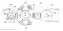
BRIEF DESCRIPTION OF THE DRAWINGSFIG. 1 is a fragmentary side elevation view, shown in somewhat diagrammatic form, of a pad transferring assembly of this invention.
FIG. 2 is a perspective fragmentary, diagrammatic view, showing the related apparatus by means of phantom lines and illustrating the path of movement of pads moving in accordance with the invention.
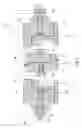
FIG. 3 is a bottom view of the apparatus of the invention.
FIG. 4 is a side elevation view of the apparatus of the invention.
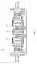
FIG. 5 is a simplified cross sectional view of the apparatus of the invention.
DESCRIPTION OF THE PREFERRED EMBODIMENTAlthough the disclosure hereof is detailed and exact to enable those skilled in the art to practice the invention, the physical embodiments herein disclosed merely exemplify the invention which may be embodied in other specific structures. While the preferred embodiment has been described, the details may be changed without departing from the invention, which is defined by the claims.
Referring more particularly to the drawings, there is seen in FIG. 1 a transfer device 10 of the present invention. The transfer device 10 is adapted to receive a series of articles from a pad turning device 12 which includes a plurality of radially extending transfer heads 16. The pad turning device 12 may be, for example, a rotary pad turner of the type more fully described in U.S. Pat. No. 5,025,910. The articles 14, such as absorbent pads, may be any elongated articles which need to be rotated 90° during the course of a manufacturing operation. Such pad turning devices 12 are especially needed and are suited for use in connection with the manufacture and packaging of sanitary napkins as well as absorbent pads which are used in the assembly of disposable garments such as adult incontinence garments or children's training pants.
Also seen in FIG. 1, articles 14 are successively and individually picked-up by the transfer heads 16 of the pad transfer device 12. In the illustrated embodiment, the pads 14 are picked up from a vacuum drum 20 which is provided for use, in the nature of an anvil, for cutting a web 22 of absorbent material into individual pads 14 utilizing a rotary cutting device 24 of a type well known in the art. Various conventional conveying and direction changing devices such as rollers may be employed in the feeding of the web and do not form a part of this invention.
After the articles 14 have been rotated 90 degrees, they are picked-up by the transfer device 10 of this invention. In this sense, a canted pitch changer 43 is provided which stretches the articles 14, as will be described below, and deposits them in that condition onto another conveyor 28 as it travels around the outer surface of a drum 26. A conveyor 28 transports the articles 14 for further processing or to a packaging device, as required by a particular application.
Referring to FIG. 2, there is seen a diagrammatic depiction of the travel path of the web 22 and the resultant pads 14 which are formed therefrom. In this depiction the various apparatus have been eliminated but are partially illustrated by means of phantom lines.
The article transfer device 10, and particularly the canted pitch changer 43 of this invention is more fully shown in FIGS. 3-4.
As shown in FIG. 3, the transfer device 10, and canted pitch changer 43 includes a central cylindrical section 30 and a pair of canted outboard sections 32, 34. The center cylindrical section 30 is adapted to hold and transfer the center of the article 14. The canted outboard sections 32, 34 are in the form of truncated cones which have their central rotational axis at an oblique angle relative to the central cylindrical section 30. Due to this oblique angle the surfaces of the outboard sections 32, 34 slope toward the center cylindrical section 30 at the pad acquisition point. However, the surfaces of the outboard sections 32, 34 and the central section 30 come into approximate alignment with each other at the opposite side of the device, i.e. the pad drop off point. This configuration causes the pads 14 to be stretched in a lengthwise direction as the pad 14 is rotated from the pad acquisition point to the pad drop off point.
Further, as is best shown in FIG. 5, each of the center section 30 and the outboard sections 32, 34 is comprised of two separately driven segments. The separately driven segments have two advantages. First, a velocity differential between the center section 30 and outboard sections 32, 34 can be utilized to stretch the pads 14 in the cross-machine direction. Second, each segment of each section can be driven at a different velocity, such that the transfer device can be placing a first pad 14 at a first velocity at the same time a second pad 14 is being acquired at a second velocity.
In use, the transfer apparatus 10 rotates from the position adjacent the transfer heads 16 wherein the surfaces of the outboard sections 32, 34 and the center section 30 are in their most concave position, to their linear orientation at the drop-off point, the pads 14 which are being transported are each successively stretched and pulled to their maximum length. If the outboard sections 32, 34 are driven at a different velocity than the center section 30, the pads 14 will also be stretched in the cross-machine direction.
As is well known in the art, each of the segments is connected internally to a source of vacuum. A pattern of holes is provided on the surface of each segment through which the internal vacuum acts to draw the pads 14 towards the surface. The center section 30 may be provided with a surface having a greater coefficient of friction than the surfaces of the outboard sections 32, 34. Therefore, the ends of the articles 14 are able to slip across the faces of the outboard sections 32, 34 when the pad-extending tensile forces exceed the force required to overcome the effects of friction. The higher coefficient of friction of the center section 30 prevents the transferred article 14 from being pulled off the centerline of the device 10. For example, the surface of the center section 30 may be formed of a low durometer silicone rubber while the surface of the outboard sections 32, 34 may be formed of stainless steel.
Referring again to FIG. 5, the left outboard 32 section is comprised of an inner segment 42 and an outer segment 44. The right outboard section 34 is also comprised of an inner segment 46 and an outer segment 48. Each segment is separately movable and driven by a servo motor. Referring first to the left outboard section 32, the outer segment 44 is driven by a first servo motor 54 which is connected directly to the outer segment 44 by a first drive shaft 66. The inner segment 42 is connected to a second servo motor 56 by a first set of sprockets 86 and a first belt 78. Likewise, referring to the right outboard section 34, the outer segment 48 is driven by a third servo motor 58 which is directly connected to the outer segment 48 by a third drive shaft 70, while the inner segment 46 is connected to its fourth servo motor 60 by a second set of sprockets 88 and a second belt 80.
The center section 30 is comprised of a first center segment 50 and a second center segment 52. Each segment 50, 52 is separately movable and driven by a servo motor 62, 64 which is connected to the segment 50, 52 by a belt and a set of sprockets 90, 92. The first center segment 50 is driven by a fifth servo motor 62 via a third set of sprockets 88 and a third belt 82. The second center segment 52 is driven by a sixth servo motor 64 via a fourth set of sprockets 92 and a fourth belt 84.
The two segments which makes up each section could be driven by a single servo motor, but preferably, each of the segments is be separately driven so that one can be picking up articles at one velocity, while the other is depositing the articles at a different velocity. Having each outboard section 32, 34 and the center section 30 being separately driven allows the outboard sections 32, 34 and the center section 30 to be driven at different velocities. This velocity differential will allow for stretching the article 14 in the cross-machine direction. This is significant in that stretching the product reduces the amount of wrinkling which may occur as the stretched member are handed off from one device to the next.
Likewise, each segment could be driven by a mechanical drive means capable of producing the velocity changes. Eccentric or other non-circular gears could produce such a velocity changing source of power. However, servo motors are the preferred means, as they provide programmability, flexibility, and isolation of torque disturbances. A preferred embodiment of this invention uses separate drives for each of the six segments. Additional embodiments might use more than three sections, or any reasonable number of segments.
It is clear that this technology can be applied to the transfer and placement of many different types of articles in the disposable goods industry and other industries as well.
The foregoing is considered as illustrative only of the principles of the invention. Furthermore, since numerous modifications and changes will readily occur to those skilled in the art, it is not desired to limit the invention to the exact construction and operation shown and described. While the preferred embodiment has been described, the details may be changed without departing from the invention, which is defined by the claims.
Claims
I claim:1. Apparatus for transferring articles from a first moving conveying device and depositing said articles onto a second moving conveyor, comprising:
a central vacuum drum having a longitudinal central axis and being disposed to acquire and transport a central portion of an article to be transferred;
a pair of canted outboard vacuum drums, each comprising a truncated cone having a central rotational axis disposed at an oblique angle relative to that of said central vacuum drum and adapted to acquire and transport the ends of said article, wherein, due to said oblique angle faces of the outboard drums are sloped toward the center of the article, wherein, due to said oblique angle faces of the outboard drums are sloped toward the center of the article at its acquisition point and are parallel to and generally in a plane with the face of the central drum at the deposition point;
said central drum and each of said outboard drums being independently rotatable and independently controlled.
2. Apparatus according to claim 1 wherein each of said drums comprises two separate segments.
3. Apparatus according to claim 2 wherein each drum segment is independently rotatable and independently controlled.
4. Apparatus for picking up an article from the periphery of a generally toroidal surface, stretching said article to a fully extended condition, rotating said article 180° and placing it on a flat moving conveyor surface comprising:
a central vacuum drum disposed to acquire and transport a central portion of an article to be transferred;
a pair of canted outboard vacuum drums, each comprising a truncated cone with an inboard diameter smaller than its outside diameter and having a central rotational axis disposed at an oblique angle relative to that of said central vacuum drum and being adapted to acquire and transport the ends of said article, wherein said oblique angle is such that the faces of the outboard drums are sloped toward the center of the article at its acquisition point and are approximately parallel to and generally in plane with the face of the central drum at the deposition point;
said central drum and each of said outboard drums being independently rotatable and independently controlled.
5. Apparatus for successively rotating and transferring articles traveling in an array of discrete articles comprising:
a rotatable drive means including a rotatable hub having a plurality of transfer head assemblies mounted thereon for rotation of the transfer heads around a closed path passing through an acquisition zone where articles are picked up and a discharge zone;
a plurality of radially extending supports disposed around the rotatable hub, each supporting a convexly shaped first transfer device mounted transversely to its respective one of said supports and a rotatable axis of said support;
a second transfer device located at said discharge zone and being adapted to successively receive articles of said array of discrete articles from said first transfer devices; said second transfer device located at said discharge zone and being adapted to successively receive article of said array of discrete articles from said first transfer devices;
said second transfer device comprising a central vacuum drum disposed to acquire and transport a central portion of an article to be transferred and a pair of canted outboard vacuum drums, each being in the shape of a truncated cone having a central rotational axis disposed at an oblique angle relative to that of said central vacuum drum and adapted to acquire and transport the ends of said article, wherein said oblique angle is such that the faces of the outboard drums are sloped toward the center of the article at its acquisition point and are approximately parallel to and generally in a plane with the face of the central drum a the deposition point;
said central drum and each of said outboard drums being independently rotatable and independently controlled.
6. Apparatus according to claim 5 wherein each of said drums comprises two separate segments.
7. Apparatus according to claim 6 wherein each drum segment is independently rotatable and independently controlled.
8. Apparatus for acquiring a succession of transversely oriented articles from a rotary device, rotating, extending the length of said articles and transferring said articles to a flat conveyor, comprising:
a center vacuum drum section, disposed to acquire and carry the center of each successive article to be transferred;
a pair of outboard canted vacuum drums, each drum comprising a truncated cone section and disposed so as to acquire and carry an end of each successive product, wherein the angle of cant is such that at the point of most acute angle, the faces of the vacuum drum are approximately parallel to the ends of a presented article at its acquisition point and are parallel to and generally in plane with the face of the center vacuum drum section at the deposition point;
said central vacuum drum and each of said outboard drums being independently rotatable and independently controlled.
9. Apparatus according to claim 8 wherein each of said drums comprises two separate segments.
10. Apparatus according to claim 9 wherein each drum segment is independently rotatable and independently controlled.
Images & Drawings included:


Sources:
- United States Patent and Trademark Office - verify current appl. status at the USPTO↗
Similar patent applications:
Recent applications in this class:
- » 20250171247 2025-05-29
SPRING TRANSFER APPARATUS AND METHOD - » 20250051104 2025-02-13
CHIP TURRET SORTING APPARATUS AND FORMATION METHOD THEREOF - » 20240327135 2024-10-03
TRANSPORT DEVICE - » 20240228188 2024-07-11
Conveyor device for advancing articles and method for labelling articles - » 20240132301 2024-04-25
Conveyor device for advancing articles and method for labelling articles - » 20220411204 2022-12-29
Method and apparatus for depositing discrete elements on a support element - » 20220258989 2022-08-18
Container screening device - » 20220063930 2022-03-03
Quick change transfer assembly - » 20210371211 2021-12-02
Adjustable vacuum wheel - » 20200140210 2020-05-07
Transfer wheel and method for transferring objects
Recent applications for this Assignee:
- » 20230339714 2023-10-26
SYSTEM AND METHOD FOR STABILIZING WEB POSITION DURING SPLICING OF TRANSVERSELY WOUND MATERIAL ROLLS - » 20230181379 2023-06-15
Apparatus and method of manufacturing an elastic composite structure for an absorbent sanitary product - » 20230101562 2023-03-30
AN ELASTIC COMPOSITE STRUCTURE FOR AN ABSORBENT SANITARY PRODUCT AND AN APPARATUS AND METHOD FOR MAKING SAID ELASTIC COMPOSITE STRUCTURE - » 20220347998 2022-11-03
Closed-loop adjustment system and method for gap control and leveling of ultrasonic devices - » 20220324669 2022-10-13
Disposable product assembly systems and methods - » 20220088885 2022-03-24
Method and apparatus for improved ultrasonic bonding - » 20220071809 2022-03-10
Curved elastic with entrapment - » 20210300716 2021-09-30
Apparatus and method for applying parallel flared elastics to disposable products and disposable products containing parallel flared elastics - » 20210300707 2021-09-30
Apparatus and method for web twist defect correction - » 20210267812 2021-09-02
Configurable single transfer insert placement method and apparatus