Retainer for supporting valve shaft in variable intake system
US20070079802A1
2007-04-12
11/281,101
2005-11-16
✅ Patent granted
US 7,434,559 B2
2008-10-14
-
-
Stephen K. Cronin | Hyder Ali
2026-05-09
Abstract:
A retainer device is provided suitable for supporting a valve shaft in a variable intake system. Preferred retainer devices can stably support a valve shaft of a variable intake system and may suitably include a shaft support part that can engage a valve shaft of the variable intake system; a fork part that can engage a valve shaft locking bolt; and a stop part spaced from the fork part by a distance sufficient to position the locking bolt between the fork part and the stop part. In preferred systems, even if a valve shaft locking bolt fastening the valve shaft is undesirably loosened during engine operation, the locking bolt is prevented from being completely removed from the retainer, thereby avoiding potential engine damage.
Assignee:
- Kia Motors Corporation 8,327 🇰🇷 Seoul, South Korea
- Hyundai Motor Company 20,646 🇰🇷 Seoul, South Korea
Interested in similar patents?
Get notified when new applications in this technology area are published.
Classification:
F02D9/1095 » CPC main
Controlling engines by throttling air or fuel-and-air induction conduits or exhaust conduits; Throttle valves specially adapted therefor; Arrangements of such valves in conduits having pivotally-mounted flaps having two or more flaps Rotating on a common axis, e.g. having a common shaft
F02B27/0215 » CPC further
Use of kinetic or wave energy of charge in induction systems, or of combustion residues in exhaust systems, for improving quantity of charge or for increasing removal of combustion residues the systems having variable, i.e. adjustable, cross-sectional areas, chambers of variable volume, or like variable means characterised by the charging effect Oscillating pipe charging, i.e. variable intake pipe length charging
F02B27/0273 » CPC further
Use of kinetic or wave energy of charge in induction systems, or of combustion residues in exhaust systems, for improving quantity of charge or for increasing removal of combustion residues the systems having variable, i.e. adjustable, cross-sectional areas, chambers of variable volume, or like variable means characterised by the means generating the charging effect; Valves Flap valves
F02D9/106 » CPC further
Controlling engines by throttling air or fuel-and-air induction conduits or exhaust conduits; Throttle valves specially adapted therefor; Arrangements of such valves in conduits having pivotally-mounted flaps; Details of the valve housing Sealing of the valve shaft in the housing, e.g. details of the bearings
F02M35/10085 » CPC further
Combustion-air cleaners, air intakes, intake silencers, or induction systems specially adapted for, or arranged on, internal-combustion engines; Air intakes; Induction systems characterised by the position of elements of the air intake system in direction of the air intake flow, i.e. between ambient air inlet and supply to the combustion chamber; Connections of intake systems to the engine having a connecting piece, e.g. a flange, between the engine and the air intake being foreseen with a throttle valve, fuel injector, mixture ducts or the like
F02M35/10255 » CPC further
Combustion-air cleaners, air intakes, intake silencers, or induction systems specially adapted for, or arranged on, internal-combustion engines; Air intakes; Induction systems; Devices or means connected to or integrated into air intakes; Air intakes combined with other engine or vehicle parts Arrangements of valves; Multi-way valves
Y02T10/12 » CPC further
Road transport of goods or passengers; Internal combustion engine [ICE] based vehicles Improving ICE efficiencies
Y02T10/12 » CPC further
Road transport of goods or passengers; Internal combustion engine [ICE] based vehicles Improving ICE efficiencies
F02D9/10 IPC
Controlling engines by throttling air or fuel-and-air induction conduits or exhaust conduits; Throttle valves specially adapted therefor; Arrangements of such valves in conduits having pivotally-mounted flaps
F02M35/10 IPC
Combustion-air cleaners, air intakes, intake silencers, or induction systems specially adapted for, or arranged on, internal-combustion engines Air intakes; Induction systems
Description
CROSS-REFERENCE TO RELATED APPLICATIONSThe present application is based on, and claims priority from, Korean Application Serial Number 10-2005-0094271, filed on Oct. 7, 2005, the disclosure of which is hereby incorporated by reference herein in its entirety.
FIELD OF THE INVENTIONThe present invention relates to retainers for supporting valve shafts in variable intake systems and, more particularly, to a retainer which is installed in an intake manifold assembly and is used for supporting a valve that changes the length of a runner.
BACKGROUND OF THE INVENTIONAs well known to those skilled in the art, a variable intake system adjusts the length of a runner of an intake manifold, through which air to be drawn into a combustion chamber passes, depending on the engine operating conditions, thus enhancing the performance of the engine.
To adjust the length of the runner through which intake air passes, a plurality of valves is rotatably provided on a valve shaft in the intake manifold assembly. A plurality of retainers and a plurality of locking bolts are used for installation of the valve shaft.
The retainers and locking bolts to be used for retaining the valve shaft must stably support the valve, and the stable installation state must be maintained.
The information set forth in this Background of the Invention section is only for enhancement of understanding of the invention and should not be taken as an acknowledgement or any form of suggestion that this information forms the prior art that is already known to a person skilled in the art.
SUMMARY OF THE INVENTIONIn one aspect, a retainer device is provided which preferably can stably support a valve shaft of a variable intake system, and in which, even if a locking bolt fastening the valve shaft is undesirably loosened during the operation of an engine, the locking bolt is prevented from being completely removed from the retainer which supports the valve shaft, thereby avoiding potential engine damage.
A retainer for supporting a valve shaft of a variable intake system according to a preferred embodiment of the present invention includes a shaft support part suitably provided at a medial portion of a retainer body to receive and support the valve shaft of the variable intake system. A fork part is provided suitably on each end of the medial portion of the retainer body, so that a shank part of a locking bolt is inserted into the fork part. A stop part is suitably provided on each end of the medial portion of the retainer body and spaced apart from each fork part by a predetermined distance sufficient to place a head part of the locking bolt between the fork part and the stop part, with a tool passing hole formed in each stop part so that a tool for tightening the locking bolt is allowed to pass through the tool passing hole of the stop part.
Vehicular variable intake systems also are provided that comprise a retainer device as disclosed herein.
It is understood that the term “vehicle” or “vehicular” or other similar terms as used herein is inclusive of motor vehicles in general such as passenger automobiles, buses, trucks, various commercial vehicles, watercraft including a variety of boats, aircraft, and the like.
Other aspects of the invention are discussed below.
BRIEF DESCRIPTION OF THE DRAWINGSFor a better understanding of the nature and objects of the present invention, reference should be made to the following detailed description with the accompanying drawings, in which:
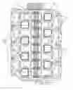
FIG. 1 is a bottom view showing the inner construction of an intake manifold assembly, in which a valve shaft of a valve is supported by a retainer according to an embodiment of the present invention;
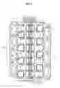
FIG. 2 is a detailed view showing an enlargement of a portion of the intake manifold assembly of FIG. 1; and
FIGS. 3 and 4 are detailed perspective views showing the retainer according to the present invention.
DETAILED DESCRIPTION OF PREFERRED EMBODIMENTSAs discussed above, in one aspect, a retainer is advantageously employed with a variable intake system of a motor vehicle or other vehicle, including to support a valve shaft of the variable intake system.
Preferred retainer devices suitably include a shaft support part that can engage a valve shaft of a variable intake system, e.g. to receive and support the valve shaft. Preferably, the shaft support part is provided at a middle or medial portion or area of the retainer body.
In preferred retain devices, the shaft support part is provided with a shaft insertion mouth oriented such that a valve shaft can be inserted into the shaft support part in a direction opposite to screw motion of the valve shaft locking bolt when being tightened. Preferably, a valve shaft can be press fit into the shaft insertion mouth. For instance, in one preferred design, the shaft insertion mouth is smaller than a diameter of the valve shaft whereby the valve shaft can be fitted or securely nested into the shaft support part using elastic strain of the shaft support part.
Preferred retainer devices also may suitably include a fork part. Suitably, a valve shaft locking bolt can engage the fork part, e.g. wherein a shank part of a locking bolt can engage such insert into the fork part. Preferred fork parts also include those that are provided on each end of the medial portion of the retainer body.
Preferred fork parts also may include one or more support arms extending outwards from the shaft support part. In preferred systems, two support arms are employed. Preferably, one or more stop protrusions protrude from the support arms to inhibit withdrawal of the locking bolt inserted between the support arms.
Preferred retainer devices also may suitably include a stop part. Suitable stop parts include those that may be spaced from each fork part by distance sufficient to place a head part of the valve shaft locking bolt between the fork part and the stop part. Preferred stop parts also may include a tool-passing hole or aperture whereby a tool for manipulating (e.g., tightening) the locking bolt can pass through the stop part aperture. In preferred designs, a stop part may be positioned on each end of the medial portion of the retainer body.
Preferred embodiments of the present invention are now described with reference to the attached drawings.
FIG. 1 is a bottom view showing the inner construction of a variable intake system to which the present invention is suitably applied. As shown in FIG. 1, a plurality of valves 3 each having a flap is rotatably provided on a valve shaft 5, which is suitably supported along a longitudinal central line in an intake manifold assembly 1. A plurality of runners 7, which communicate with combustion chambers, is disposed on opposite sides of the valves 3.
The structure supporting the valve shaft 5 using retainers 9 is shown in FIG. 2 in detail.
Referring to FIGS. 3 and 4, each retainer 9 according to a preferred embodiment of the present invention includes a shaft support part 1, which is provided suitably in a medial portion of a retainer body to receive and support the valve shaft 5, and a fork part 5, which is suitably provided on each end of the medial portion of the retainer body so that a shank part of a locking bolt 13 can be conveniently inserted into the fork part 5. The retainer 9 suitably further includes a stop part 19, which is provided on each end of the medial portion of the retainer body and is suitably spaced apart from each fork part 5 by a distance sufficient to place a head part of the locking bolt 13 between the fork part 15 and the stop part 19. A tool-passing hole 17 is preferably formed in each stop part 19 so that a tool for tightening or otherwise adjusting the locking bolt 13 is allowed to pass through the tool passing hole 17 of the stop part 19.
In preferred designs, the shaft support part 11 includes a shaft insertion mouth 21 oriented such that the valve shaft 5 is inserted into the shaft support part 11 in a direction opposite the screw motion of the locking bolt 13 when tightened. The size of the shaft insertion mouth 21 is suitably smaller than the diameter of the valve shaft 5, so that the valve shaft 5 can be secured in the shaft support part 11 by elastic strain of the shaft support part 11.
It thus can be preferable that the retainer 9 be made of plastic or other malleable material, allowing slight elastic deformation of the retainer 9 and providing press-fit engagement of the valve shaft.
In preferred designs, each fork part 15 includes two support arms 23 which extend outwards from the shaft support part 11. A stop protrusion 25 preferably protrudes from each support arm 23 so as to prevent the locking bolt 13 inserted between the support arms 23 from being undesirably removed from the support arms 23.
Thus, in such preferred designs, when the locking bolt 13 is coupled to the retainer 9, the shank part of the locking bolt 13 can expand space defined between the stop protrusions 25 and can be inserted into the support arms 23. After the insertion of the locking bolt 13 has been completed, the locking bolt 13 is prevented from undesirable removal from the support arms 23 by the stop protrusions 25.
Furthermore, in preferred designs, the diameter of each tool-passing hole 17 is smaller than the diameter of the head part of the locking bolt 13 and is larger than the diameter of a tool to be inserted into the tool-passing hole 17 to tighten or otherwise manipulate the locking bolt 13.
By such arrangement, where the shank part of the locking bolt 13 widens the stop protrusions 13 and is inserted into the support arms 23, the locking bolt 13 can be prevented from being undesirably removed from the support arms 23.
The retainers 9 may be assembled with the intake manifold assembly 1 suitably using the locking bolts 13, which are coupled to the retainers 9 through the above-mentioned process. Thereafter, the valve shaft 5 is fitted into the shaft support parts 11 of the retainers 9, thus completing installation of the valves 3. In the intake manifold assembly 1 to which the valves 3 are mounted, the valve shaft 5 is stably supported by the shaft support parts 11 of the retainers 9, so that stable operation of the engine can be ensured. Even if a locking bolt 13 is loosened due to vibration of the engine, the locking bolts 13 cannot be completely removed from the intake manifold assembly 1, thus avoiding undesirable entry of the locking bolt 13 into a combustion chamber.
As a consequence, systems of the invention can notably increase the reliability of an engine.
As is apparent from the foregoing, in preferred aspects, retainers of the invention are able to stably support a valve shaft of a variable intake system. Furthermore, in preferred systems of the invention, even if a locking bolt fastening the valve shaft is undesirably loosened during engine operation, the locking bolt is prevented from being completely removed from the retainer that supports the valve shaft, thus preventing potential engine damage to the engine.
While the invention has been described with reference to specific embodiments, modifications and variations may be constructed without departing from the scope of the invention, which is defined in the following claims.
Claims
What is claimed is:1. A retainer for supporting a valve shaft of a variable intake system, comprising:
a shaft support part provided at a medial portion of a retainer body to receive and support the valve shaft of the variable intake system;
a fork part provided on each end of the medial portion of the retainer body, so that a shank part of a locking bolt is inserted into the fork part; and
a stop part provided on each end of the medial portion of the retainer body and spaced apart from each fork part by a predetermined distance sufficient to place a head part of the locking bolt between the fork part and the stop part, with a tool passing hole formed in each stop part so that a tool for tightening the locking bolt is allowed to pass through the tool passing hole of the stop part.
2. The retainer of claim 1, wherein the shaft support part is provided with a shaft insertion mouth oriented such that the valve shaft is inserted into the shaft support part in a direction opposite to screw motion of the locking bolt when being tightened, and a size of the shaft insertion mouth is smaller than a diameter of the valve shaft, so that the valve shaft is fitted into the shaft support part using elastic strain of the shaft support part.
3. The retainer of claim 2, wherein each fork part comprises:
two support arms extending outwards from the shaft support part; and
stop protrusions protruding from the support arms to prevent the locking bolt inserted between the support arms from being removed from the support arms.
4. A retainer for engaging a valve shaft of a variable intake system, comprising:
a shaft support part that can engage a valve shaft of the variable intake system;
a fork part that can engage a valve shaft locking bolt; and
a stop part spaced from the fork part by a distance sufficient to position the locking bolt between the fork part and the stop part.
5. The retainer of claim 4 wherein an aperture is in the stop part whereby a tool can be advanced therethrough to manipulate locking bolt.
6. The retainer of claim 4 wherein the shaft support part is provided with a shaft insertion mouth oriented such that the valve shaft can be inserted into the shaft support part in a direction opposite to screw motion of the locking bolt when being tightened.
7. The retainer of claim 6 wherein a valve shaft can be press fit into the shaft insertion mouth.
8. The retainer of claim 6 wherein the shaft insertion mouth is smaller than a diameter of the valve shaft whereby the valve shaft can be fitted into the shaft support part using elastic strain of the shaft support part.
9. The retainer of 4 wherein the fork part comprises one or more support arms extending outwards from the shaft support part.
10. The retainer of claim 9 wherein the fork part further comprises one or more stop protrusions protruding from the support arms to inhibit withdrawal of the locking bolt inserted between the support arms.
11. A vehicular variable intake system comprising the retainer of claim 1.
12. The system of claim 11 wherein a valve shaft engages the retainer.
13. A vehicular variable intake system comprising the retainer of claim 4.
14. The system of claim 11 wherein a valve shaft engages the retainer.
Images & Drawings included:


Sources:
- United States Patent and Trademark Office - verify current appl. status at the USPTO↗
Recent applications in this class:
- » 20240263591 2024-08-08
THROTTLE DEVICE - » 20200248635 2020-08-06
Low pressure fuel injection system for a multi-cylinder light-duty internal combustion engine - » 20200131999 2020-04-30
AIRFLOW CONTROL VALVE STRUCTURE - » 20190277203 2019-09-12
Throttle device - » 20190195146 2019-06-27
Valve device - » 20180066592 2018-03-08
Intake module of a fresh air system - » 20150034192 2015-02-05
Valve assembly and exhaust gas system - » 20140305523 2014-10-16
Intake pipe for gas of an internal combustion engine with a flap unit - » 20130037000 2013-02-14
Valve device with at least two separately produced valves assembled together for joint movement - » 20120210970 2012-08-23
Assembly and method for controlling an air intake runner
Recent applications for this Assignee:
- » 20250293967 2025-09-18
VEHICLE CONTROL APPARATUS AND METHOD THEREOF - » 20250293557 2025-09-18
MOTOR WITH A COOLING STRUCTURE - » 20250293373 2025-09-18
BATTERY ASSEMBLY - » 20250293361 2025-09-18
FUEL CELL POWER GENERATION MODULE - » 20250293308 2025-09-18
ELECTRODE ASSEMBLY AND ALL-SOLID STATE BATTERY INCLUDING THE SAME - » 20250292638 2025-09-18
SYSTEM AND METHOD FOR MONITORING POWER OF A VEHICLE - » 20250292590 2025-09-18
METHOD AND APPARATUS FOR CONTEXT-RECOGNITION OBJECT ACTION PREDICTION AND PATH PLANNING FOR AUTONOMOUS VEHICLES BASED ON PEDESTRIAN MOTION PREDICTION - » 20250290600 2025-09-18
PRESSURE VESSEL - » 20250289441 2025-09-18
METHOD AND APPARATUS FOR CALIBRATING ORIENTATION ANGLE OF VEHICLE SENSOR - » 20250289422 2025-09-18
SYSTEM AND METHOD FOR GENERATING EMERGENCY COLLISION AVOIDANCE STRATEGY FOR A VEHICLE