Method of making a post cover and a post cover made in accordance with the method
US20070101674A1
2007-05-10
11/541,624
2006-09-29
Abstract:
A method of making a post cover. A first step involves providing a rigid elongate substrate having a first face, a second face, a first side edge and a second side edge, with parallel “V” grooves positioned lengthwise in the first face and a flexible backing covering the second face. A second step involves placing glue in all but one of the “V” grooves and forming the substrate into a tube, with the flexible backing covering the one “V” groove left unglued serving as a hinge which allows the tube to open and close lengthwise around a post.
Interested in similar patents?
Get notified when new applications in this technology area are published.
Classification:
B29C66/4322 » CPC main
General aspects of processes or apparatus for joining preformed parts; General aspects of joining substantially flat articles, e.g. plates, sheets or web-like materials; Making flat seams in tubular or hollow articles; Joining single elements to substantially flat surfaces; Joining substantially flat articles ; Making flat seams in tubular or hollow articles; Joining a relatively small portion of the surface of said articles for making tubular articles or closed loops, e.g. by joining several sheets ; for making hollow articles or hollow preforms by joining a single sheet to itself
B29C53/066 » CPC further
Shaping by bending, folding, twisting, straightening or flattening; Apparatus therefor; Bending or folding of plates or sheets; Forming folding lines by pressing or scoring combined with folding and joining the sides of the folding line, e.g. "Abkantschweissen"
B29C53/40 » CPC further
Shaping by bending, folding, twisting, straightening or flattening; Apparatus therefor; Bending and joining, e.g. for making hollow articles by bending sheets or strips at right angles to the longitudinal axis of the article being formed and joining the edges for articles of definite length, i.e. discrete articles
B29C65/48 » CPC further
Joining of preformed parts ; Apparatus therefor using adhesives, i.e. using supplementary joining material; solvent bonding
B29C66/1162 » CPC further
General aspects of processes or apparatus for joining preformed parts; General aspects dealing with the joint area or with the area to be joined; Particular design of joint configurations particular design of the joint cross-sections; Joint cross-sections comprising a single joint-segment, i.e. one of the parts to be joined comprising a single joint-segment in the joint cross-section; Single bevelled joints, i.e. one of the parts to be joined being bevelled in the joint area Single bevel to bevel joints, e.g. mitre joints
B29C66/43 » CPC further
General aspects of processes or apparatus for joining preformed parts; General aspects of joining substantially flat articles, e.g. plates, sheets or web-like materials; Making flat seams in tubular or hollow articles; Joining single elements to substantially flat surfaces; Joining substantially flat articles ; Making flat seams in tubular or hollow articles Joining a relatively small portion of the surface of said articles
B29C66/496 » CPC further
General aspects of processes or apparatus for joining preformed parts; General aspects of joining substantially flat articles, e.g. plates, sheets or web-like materials; Making flat seams in tubular or hollow articles; Joining single elements to substantially flat surfaces; Internally supporting the, e.g. tubular, article during joining using a support which remains in the joined object
E04C2/328 » CPC further
Building elements of relatively thin form for the construction of parts of buildings, e.g. sheet materials, slabs, or panels characterised by the shape or structure formed of corrugated or otherwise indented sheet-like material; composed of such layers with or without layers of flat sheet-like material slightly bowed or folded panels not otherwise provided for
E04F13/0733 » CPC further
Coverings or linings, e.g. for walls or ceilings composed of covering or lining elements; Sub-structures therefor; Fastening means therefor composed of specially adapted, structured or shaped covering or lining elements for particular building parts, e.g. corners or columns for corners
B29L2023/22 » CPC further
Tubular articles Tubes or pipes, i.e. rigid
B29L2031/766 » CPC further
Other particular articles Poles, masts, posts
E04F2203/08 » CPC further
Specially structured or shaped covering, lining or flooring elements not otherwise provided for with a plurality of grooves or slits in the back side, to increase the flexibility or bendability of the elements
Y10T156/1002 » CPC further
Adhesive bonding and miscellaneous chemical manufacture; Methods of surface bonding and/or assembly therefor with permanent bending or reshaping or surface deformation of self sustaining lamina
Y10T156/1013 » CPC further
Adhesive bonding and miscellaneous chemical manufacture; Methods of surface bonding and/or assembly therefor with permanent bending or reshaping or surface deformation of self sustaining lamina; Running or continuous length work; Longitudinal bending and edge-joining of one piece blank to form tube
B29C53/00 IPC
Shaping by bending, folding, twisting, straightening or flattening; Apparatus therefor
B29C65/00 IPC
Joining of preformed parts ; Apparatus therefor
E04C3/30 » CPC further
Structural elongated elements designed for load-supporting Columns; Pillars; Struts
Description
This application claims priority from Canadian Application Serial No. 2,527,184 filed Nov. 10, 2005.
FIELD OF THE INVENTIONThe present invention relates to a method of making a post cover and a post cover made in accordance with the teachings of the method.
BACKGROUND OF THE INVENTIONU.S. Pat. No. 5,987,845 (Laronde 1999) discloses an invention relating to post covers entitled “Post cover with tongue and groove joint”.
SUMMARY OF THE INVENTIONAccording to one aspect of the present invention there is provided a method of making a post cover. A first step involves providing a rigid elongate substrate having a first face, a second face, a first side edge and a second side edge, with parallel “V” grooves positioned lengthwise in the first face and a flexible backing covering the second face. A second step involves placing glue in all but one of the “V” grooves and forming the substrate into a tube, with the flexible backing covering the one “V” groove left unglued serving as a hinge which allows the tube to open and close lengthwise around a post.
According to another aspect of the present invention there is provided a post cover which includes a tubular body formed out of a rigid elongate substrate having an interior face, an exterior face, a first side edge and a second side edge. The exterior face is substantially covered by a flexible substrate. The interior face has a plurality of parallel “V” grooves positioned lengthwise, all but one of the “V” grooves being glued. The flexible backing covering the one “V” groove left unglued serves as a hinge which allows the tube to open and close lengthwise around a post.
BRIEF DESCRIPTION OF THE DRAWINGSThese and other features of the invention will become more apparent from the following description in which reference is made to the appended drawings, the drawings are for the purpose of illustration only and are not intended to in any way limit the scope of the invention to the particular embodiment or embodiments shown, wherein:
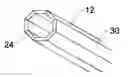
FIG. 1 is a perspective view of a post cover constructed in accordance with the teachings of the present invention.
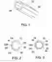
FIG. 2 is an end elevation view of the post cover illustrated in FIG. 1, in an open position.
FIG. 3 is an end elevation view of the post cover illustrated in FIG. 1, in a closed position around a post.
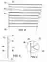
FIG. 4 is a top plan view of a rigid substrate used in the construction of the post cover illustrated in FIG. 1.
FIG. 5 is an end elevation view of the rigid substrate illustrated in FIG. 4.
FIG. 6 is a detailed end elevation view of the rigid substrate illustrated in FIG. 5.
DETAILED DESCRIPTION OF THE PREFERRED EMBODIMENTThe preferred method of making a post cover will now be described with reference to FIG. 1 through 6.
Referring now to FIG. 4, the method of making a post cover begins with the steps of providing a rigid elongate substrate 12 having, referring to FIG. 5, a first face 14, a second face 16, a first side edge 18 and a second side edge 20. Parallel “V” grooves 22 are positioned lengthwise in first face 14 and a flexible backing 24 covers second face 16. Referring to FIG. 6, glue 28 is then placed in all but one of the “V” grooves 22. Referring to FIG. 5, the unglued “V” groove is labelled 22A. Referring to FIG. 2, substrate 12 is then formed into a tube 30, with flexible backing 24 covering the one “V” groove 22A left unglued. Unglued “V” groove 22A can then serve as a hinge which allows tube 30 to open and close lengthwise around a post 32. Referring to FIG. 3, when the tube is positioned around post 32, first side edge 18 and second side edge 20 are secured together to prevent removal of post 32.
As examples, rigid substrate 12 may be made from made from drywall, MDF, plastic, or any other suitable rigid material and flexible backing 24 may be made from drywall paper, resin impregnated paper, cloth, or any other suitable material that is sufficiently strong and flexible. Also, referring to FIG. 4, rigid substrate 12 is divided into eight sections by “V” grooves 22. The angle of each groove 22 is sufficient to create a closed polygon with all surfaces touching, such that glue 28 can bond them together. It will be understood that any reasonable number of sets of “V” grooves 22 may be used, with an appropriate angle used.
Cautionary Warnings:
Care must be taken when selecting the flexible backing. The flexible backing must be strong enough to act as a hinge. When it acts as a hinge, the stress on the outside of the bend always exceeds the stress on the inside of the bend. If the flexible backing is not strong enough, it will tear. Conversely, if the backing is too thick, surface defects will appear in the form of creases or bubbles. For best results, a material that will provide strength and flexibility ought to be used, examples of which are given above.
In this patent document, the word “comprising” is used in its non-limiting sense to mean that items following the word are included, but items not specifically mentioned are not excluded. A reference to an element by the indefinite article “a” does not exclude the possibility that more than one of the element is present, unless the context clearly requires that there be one and only one of the elements.
It will be apparent to one skilled in the art that modifications may be made to the illustrated embodiment without departing from the spirit and scope of the invention as hereinafter defined in the Claims.
Claims
What is claimed is:1. A method of making a post cover, comprising the steps of:
providing a rigid elongate substrate having a first face, a second face, a first side edge and a second side edge, parallel “V” grooves positioned lengthwise in the first face and a flexible backing covering the second face;
placing glue in all but one of the “V” grooves and forming the substrate into a tube, with the flexible backing covering the one “V” groove left unglued serving as a hinge which allows the tube to open and close lengthwise around a post.
2. The method as defined in claim 1, including a step of positioning the tube around a post and securing the first side edge and the second side edge together to prevent removal of the post.
3. The method as defined in claim 1, the rigid substrate being drywall and the flexible backing being drywall paper.
4. The method as defined in claim 1, the rigid substrate being wooden slats.
5. The method as defined in claim 4, the flexible backing being drywall paper.
6. A post cover, comprising:
a tubular body formed out of a rigid elongate substrate having an interior face, an exterior face, a first side edge and a second side edge, the exterior face being substantially covered by a flexible substrate, the interior face having a plurality of parallel “V” grooves positioned lengthwise, all but one of the “V” grooves being glued, the flexible backing covering the one “V” groove left unglued serving as a hinge which allows the tube to open and close lengthwise around a post.
7. The post cover as defined in claim 6, wherein the rigid substrate is drywall and the flexible backing is drywall paper.
8. The post cover as defined in claim 6, wherein the rigid substrate is wooden slats.
9. The post cover as defined in claim 8, wherein the flexible backing is drywall paper.
Images & Drawings included:
Sources:
- United States Patent and Trademark Office - verify current appl. status at the USPTO↗
Recent applications in this class:
- » 20190030832 2019-01-31
Braided textile sleeve with hot-melt adhesive yarn and method of construction thereof - » 20180147791 2018-05-31
Method for producing a tube skirt decorated with an aesthetic lateral weld - » 20180133976 2018-05-17
INDUCTION HEATING SEALING DEVICE - » 20180126660 2018-05-10
Apparatus and method for stitching together leading end and trailing end of a tire component - » 20150258730 2015-09-17
Method for manufacturing high performance butterfly valve liner - » 20090105683 2009-04-23
Disposable Injection-Molded Container for Biologic Fluids and Method of Manufacture - » 20080216629 2008-09-11
Flexible belt having a planed seam and processes for making the same - » 20050228427 2005-10-13
Method of making a catheter balloon by laser fusing wrapped material