Pipe separator with improved separation
US20070102369A1
2007-05-10
10/563,291
2004-07-08
✅ Patent granted
US 7,490,671 B2
2009-02-17
WO; PCT/NO2004/000211; 20040708
WO; WO2005/005777; 20050120
Thomas A Beach
2024-11-30
Abstract:
A pipe separator for separation of fluids, for example separation of oil, gas and water in connection with the extraction and production of oil and gas from formations under the sea bed. It comprises an extended, tubular separator body (1) that has a diameter at the inlet and outlet ends that is mainly equal to or slightly greater than the diameter of the transport pipe to which the separator body is connected. A cyclone (3) is arranged upstream of the separator body for separation of any gas present. An electrostatic coalescer (4) is incorporated in and constitutes an integrated part of the separator body (1).
Assignee:
- NORSK HYDRO ASA 107 🇳🇴 Oslo, Norway
Interested in similar patents?
Get notified when new applications in this technology area are published.
Classification:
E21B43/40 » CPC main
Methods or apparatus for obtaining oil, gas, water, soluble or meltable materials or a slurry of minerals from wells; Arrangements for separating materials produced by the well Separation associated with re-injection of separated materials
B01D17/00 » CPC further
Separation of liquids, not provided for elsewhere, e.g. by thermal diffusion
B01D17/0214 » CPC further
Separation of liquids, not provided for elsewhere, e.g. by thermal diffusion; Separation of non-miscible liquids by sedimentation with removal of one of the phases
B01D17/0217 » CPC further
Separation of liquids, not provided for elsewhere, e.g. by thermal diffusion; Separation of non-miscible liquids by centrifugal force
B01D17/041 » CPC further
Separation of liquids, not provided for elsewhere, e.g. by thermal diffusion; Separation of non-miscible liquids; Breaking emulsions with moving devices
B01D17/045 » CPC further
Separation of liquids, not provided for elsewhere, e.g. by thermal diffusion; Separation of non-miscible liquids; Breaking emulsions with coalescers
B01D17/06 » CPC further
Separation of liquids, not provided for elsewhere, e.g. by thermal diffusion Separation of liquids from each other by electricity
H01R12/721 » CPC further
Structural associations of a plurality of mutually-insulated electrical connecting elements, specially adapted for printed circuits, e.g. printed circuit boards [PCBs], flat or ribbon cables, or like generally planar structures, e.g. terminal strips, terminal blocks; Coupling devices specially adapted for printed circuits, flat or ribbon cables, or like generally planar structures; Terminals specially adapted for contact with, or insertion into, printed circuits, flat or ribbon cables, or like generally planar structures; Coupling devices for rigid printing circuits or like structures coupling with the edge of the rigid printed circuits or like structures cooperating directly with the edge of the rigid printed circuits
H01R13/6335 » CPC further
Details of coupling devices of the kinds covered by groups or -; Means for facilitating engagement or disengagement of coupling parts or for holding them in engagement; Additional means for facilitating engagement or disengagement of coupling parts, e.g. aligning or guiding means, levers, gas pressure electrical locking indicators, manufacturing tolerances for disengagement only comprising a handle
H01R13/6658 » CPC further
Details of coupling devices of the kinds covered by groups or -; Structural association with built-in electrical component with built-in electronic circuit on printed circuit board
C02F1/32 IPC
Treatment of water, waste water, or sewage by irradiation with ultra-violet light
E21B29/12 IPC
Cutting or destroying pipes, packers, plugs, or wire lines, located in boreholes or wells, e.g. cutting of damaged pipes, of windows ; Deforming of pipes in boreholes or wells; Reconditioning of well casings while in the ground specially adapted for underwater installations
Description
The present invention concerns a pipe separator for separation of fluids, for example separation of oil, gas and water in connection with the extraction and production of oil and gas from formations under the sea bed, comprising an extended, tubular separator body that has a diameter at the inlet and outlet ends that is mainly equivalent to the diameter of the transport pipe to which the pipe separator is connected, a cyclone arranged upstream of the separator body for separation of any gas present and an electrostatic coalescer arranged in connection with the pipe separator.
The applicant's own Norwegian patent application nos. 19994244, 20015048, 20016216, 20020619 and 20023919 describe prior art pipe separators for the separation of oil, water and/or gas downhole, on the sea bed or on the surface, on a platform or similar. In particular, patent application no. 20023919 shows a solution in which a separate, compact electrostatic coalescer is used in connection with the pipe separator. The oil flow from the pipe separator is passed to the coalescer downstream of the pipe separator and subsequently to a further oil/water separator that removes the remaining water after separation in the pipe separator. This prior art solution is particularly designed for, but not limited to, medium heavy oils with water removal from the oil phase to 0.5% water, using a cyclone or other type of gas/liquid separator to remove gas before the pipe separator.
The solution requires an additional separator, which is complicated and expensive, and the coalescer itself, which is of a vertical type, cannot be reamed or pigged (cleaned) in the conventional manner. This also represents a considerable disadvantage of the prior art solution.
The present invention represents a considerably simplified separation solution in which the above disadvantages are avoided. The present invention is characterised in that the electrostatic coalescer is incorporated in and constitutes an integrated part of the separator body, as stated in the attached claim 1.
The dependent claims 2-5 indicate the advantageous features of the present invention.
The present invention will be described in further detail in the following with reference to the attached drawings, where:
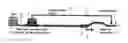
FIG. 1 shows an elementary sketch of a pipe separator in accordance with the present invention.
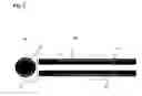
FIG. 2 shows an enlarged part of the separator shown in FIG. 1 in the area of the coalescer in a cross-section a) and a longitudinal section b).
The solution shown in FIG. 1 comprises a tubular separator body 1, a liquid seal 6, arranged downstream of the separator body, for the water phase in the fluid (oil/water) that flows through the separator, a drainage device 7 with an outlet 8 for the separated water, a pig battery 5, arranged upstream of the separator body in connection with a well head 9, a connection pipe 10 that connects the well head to the separator body 1 and a transport pipe 11 for oil downstream of the separator body. The special feature of the present invention is that a coalescer 4 is incorporated in the separator body 1 as an integrated unit. The coalescer is expediently arranged at a distance of between ⅓ and ½ of the length of the separator body from the inlet of the separator body. However, its location is not limited to this. FIG. 2 shows in large scale, in cross-section and longitudinal section, the part of the separator body in which the coalescer is incorporated. As the figure shows, the coalescer comprises an upper electrode 12 and a lower electrode 13 that are enclosed in expediently insulating material in the wall 14 of the separator body. The electrodes are designed to have applied to them (not shown in further detail) an expedient voltage “V” (AC voltage) to create an electric field that contributes to increasing the separation of water from the fluid (oil and water) flowing through the separator. As FIG. 1 shows, a cyclone 3 (or another expedient gas/liquid separator) is arranged upstream of the separator body 1 to remove any gas from the fluid that is produced in the wells 9. The intention of removing the gas is to avoid it reducing the effect of the coalescer as the gas is a poor electrical conductor. Another intention is to prevent the formation of plug flow in the separator.
The method of operation of the separator solution in accordance with the present invention is otherwise as follows:
Fluid, i.e. gas, oil and water, that is produced is passed first to the cyclone 3, where the majority of gas is removed and passed on in a separate pipe 9, possibly being reintroduced into the transport pipe 11 after the separator.
The liquid phase, which may contain small amounts of gas, is introduced into the separator body 1. Free water will separate quickly and form a water phase under the oil phase. The gas bubbles will collect in the top of the separator pipe and, depending on their concentration, form a free gas phase. When coarse separation has been completed (i.e. the water phase on the bottom, the oil phase with small oil drops in the centre and possibly a thin gas phase on the top), the fluid will pass into the integrated coalescer 4.
In the coalescer 4, a voltage drop will be created mainly over the oil zone because the water zone conducts current and the gas zone also has good conduction properties.
The voltage drop over the oil zone (alternating current) produces increased drop coalescence and destabilises the oil/water interface. The water drops grow in size and will separate quickly after the fluid has entered the pipe separator element 1 again.
In the separator element downstream of the coalescer, the coalesced water drops will be separated out and collected in the collection unit 7, where the water is drained out via the pipe 8. The oil will flow on past the water seal 6 to the transport pipe 11.
The present invention as it is defined in the claims is not limited to the example shown and described above. The separator may be provided with two or more coalescers 4 arranged in series in the separator element 1. This may be particularly relevant for oils that are difficult to separate such as heavier oils.
The cyclone 3 may also be located in places other than the well head as shown in FIG. 1. It has proved expedient for the cyclone to be located in connection with equipment that causes high shear for the fluid as this produces good separation conditions. However, it may also be relevant to locate the cyclone in close proximity to the separator's inlet in situations in which the separator is located far from the well head.
Claims
1-5. (canceled)
6. A pipe separator for separation of fluids, for example separation of oil, gas and water in connection with the extraction and production of oil and gas from formations under the sea bed, comprising an extended, tubular separator body (1) that has a diameter at the inlet and outlet ends that is mainly equal to or slightly greater than the diameter of the transport pipe to which the separator body is connected, a separator device, expediently a cyclone (3), arranged upstream of the separator body for separation of any gas present and an electrostatic coalescer (4) arranged in connection with the pipe separator, wherein the electrostatic coalescer (4) is incorporated in and constitutes an integrated part of the separator body.
7. A pipe separator in accordance with claim 6, wherein a water seal (6) is arranged downstream of the separator element (1) and a device (7) is arranged in connection with the water seal for drainage of the water that is separated out in the separator element (1).
8. A pipe separator in accordance with claim 6, wherein the separator element (1) comprises two or more coalescers arranged in series.
9. A pipe separator in accordance with claim 6, wherein the cyclone (3) is arranged in connection with a throttle valve that produces high shear for the fluid.
10. A pipe separator in accordance with claim 6, wherein the cyclone (3) is arranged in close proximity to the inlet of the separator element (1).
11. A pipe separator in accordance with claim 7, wherein the separator element (1) comprises two or more coalescers arranged in series.
12. A pipe separator in accordance with claim 7, wherein the cyclone (3) is arranged in connection with a throttle valve that produces high shear for the fluid.
13. A pipe separator in accordance with claim 7, wherein the cyclone (3) is arranged in close proximity to the inlet of the separator element (1).
Images & Drawings included:
Sources:
- United States Patent and Trademark Office - verify current appl. status at the USPTO↗
Recent applications in this class:
- » 20250059873 2025-02-20
Unlimited Sump Systems and Methods - » 20250043672 2025-02-06
Comprehensive Enerty Systems - » 20250012181 2025-01-09
Removal of Crude Oil from Water in a Gas Oil Separation Plant (GOSP) - » 20240209724 2024-06-27
SYSTEMS AND METHODS FOR PROCESSING PRODUCED OILFIELD BRINE - » 20230349280 2023-11-02
System and Method for Recycling Miscible NGLs for Oil Recovery - » 20230340868 2023-10-26
Methods and apparatus for offshore power generation and ammonia production - » 20230323764 2023-10-12
System and method for recycling miscible NGLs for oil recovery - » 20230279764 2023-09-07
Systems and methods for processing produced oilfield brine - » 20230083202 2023-03-16
Removal of Crude Oil from Water in a Gas Oil Separation Plant (GOSP) - » 20220065092 2022-03-03
Gas-lift system with paired controllers
Recent applications for this Assignee:
- » 20250283196 2025-09-11
AlSiMgX MASTER ALLOY AND USE OF THE MASTER ALLOY IN THE PRODUCTION OF AN ALUMINIUM ALLOY - » 20250270724 2025-08-28
A PROCESS AND APPARATUS FOR PRODUCTION OF ALUMINIUM, AND A PROCESS AND APPARATUS FOR PRODUCTION OF AN ALUMINIUM CHLORIDE CONTAINING FEEDSTOCK - » 20250129455 2025-04-24
HEAT TREATABLE ALUMINIUM ALLOY WITH IMPROVED MECHANICAL PROPERTIES AND METHOD FOR PRODUCING IT - » 20250019802 2025-01-16
A 6XXX ALLOY FOR EXTRUSION WITH IMPROVED PROPERTIES AND A PROCESS FOR MANUFACTURING EXTRUDED PRODUCTS - » 20240296915 2024-09-05
A METHOD FOR DEVELOPING SUSTAINABLE ALUMINIUM PRODUCTS, AND A PRODUCT PRODUCED ACCORDING TO THE METHOD - » 20240263270 2024-08-08
METHOD AND EQUIPMENT FOR TREATMENT OF MOLTEN ALUMINIUM METAL - » 20240018631 2024-01-18
A HIGH TEMPERATURE STABLE ALSICU ALLOY - » 20220176443 2022-06-09
Casting method and casting apparatus for DC casting - » 20210371949 2021-12-02
METHOD AND APPARATUS FOR POST WELD HEAT TREATMENT OF ALUMINIUM ALLOY COMPONENTS, AND A WELDED ALUMINIUM COMPONENT TREATED ACCORDING TO THE METHOD - » 20210341332 2021-11-04
Determining a presence or absence of water in a DC casting starter block : method and direct chill apparatus claims