Sewage pump
US20070102547A1
2007-05-10
11/163,955
2005-11-04
✅ Patent granted
US 7,354,009 B2
2008-04-08
-
-
Faye Francis
2026-04-08
Abstract:
A sewage pump is composed of a motor, a main shaft, an upper impeller, a lower impeller, a grinding wheel, a top cap, an upper bearing base with a mounting plate, an upper bearing base, a tube body with a wire inlet connector, a lower bearing base, a lower bearing with a mounting plate, a lower base and a vertical bypass. Improvement of the sewage pump is that the main shaft has a quad-bearing structure to minimize deflection at high speed and high pressure and has rotary seals at each end to improve stability and sealing efficiency. Moreover, the wire inlet connector is filled with epoxy filling material to protect the wire and the sewage pump further has moisture-sensors to timely stop the motor when sealing efficiency is failing. Therefore, the sewage pump has excellent efficiency, stability and durability.
Interested in similar patents?
Get notified when new applications in this technology area are published.
Classification:
F04D7/045 » CPC main
Pumps adapted for handling specific fluids, e.g. by selection of specific materials for pumps or pump parts of centrifugal type the fluids being viscous or non-homogenous with means for comminuting, mixing stirring or otherwise treating
F04D13/086 » CPC further
Pumping installations or systems; Units comprising pumps and their driving means the pump being electrically driven for submerged use the pump and drive motor are both submerged
H02K5/124 » CPC further
Casings; Enclosures; Supports; Casings or enclosures characterised by the shape, form or construction thereof specially adapted for operating in liquid or gas Sealing of shafts
H02K5/225 » CPC further
Casings; Enclosures; Supports; Casings or enclosures characterised by the shape, form or construction thereof; Auxiliary parts of casings not covered by groups -, e.g. shaped to form connection boxes or terminal boxes Terminal boxes or connection arrangements
H02K7/083 » CPC further
Arrangements for handling mechanical energy structurally associated with dynamo-electric machines, e.g. structural association with mechanical driving motors or auxiliary dynamo-electric machines; Structural association with bearings radially supporting the rotary shaft at both ends of the rotor
H02K11/20 » CPC further
Structural association of dynamo-electric machines with electric components or with devices for shielding, monitoring or protection for measuring, monitoring, testing, protecting or switching
H02K7/14 » CPC further
Arrangements for handling mechanical energy structurally associated with dynamo-electric machines, e.g. structural association with mechanical driving motors or auxiliary dynamo-electric machines Structural association with mechanical loads, e.g. with hand-held machine tools or fans
F04D29/08 IPC
Details, component parts, or accessories Sealings
B02C23/00 IPC
Auxiliary methods or auxiliary devices or accessories specially adapted for crushing or disintegrating not provided for in preceding groups or not specially adapted to apparatus covered by a single preceding group
Description
BACKGROUND OF THE INVENTION1. Field of the Invention
The present invention relates to a sewage pump, and more particularly to a sewage pump that comprises quad-bearing structures for supporting, multiple gaskets for sealing, epoxy filling material to protect wires, and a moisture-sensor to protect a motor so that the sewage pump is kept stable, durable and efficient at high speed operation.
2. Description of Related Art
Conventional sewage pump comprises single-bearing structure at a shaft end and is sealed with a single gasket so that the shaft has poor supporting strength and sealing efficiency of the conventional sewage pump is insufficient. Moreover, wires and a motor in the sewage pump are not completely protected.
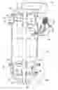
With reference to FIG. 1, the conventional sewage pump as shown in a cross-sectional side view comprises a motor 1, a main shaft 2, an upper impeller 3, a lower impeller 4, a grinder wheel 5, a top cap 6, an upper bearing base 7, a tube body 8, a wire inlet 9, a lower bearing base 10, a lower base 11 and a vertical bypass 12. In the conventional sewage pump, the motor 1 is the power source to drive the main shaft 2. The main shaft 2 penetrates the motor 1 and has an upper end engaging the upper impeller 3 and a lower end engaging the lower impeller 4 and the grinder wheel 5. The top cap 6 mounts on the zenith of the conventional sewage pump and has an inlet 61, an upper impeller chamber 62, an upper outlet 63 and a screw 64 combining the top cap 6 with the upper bearing base 7. The upper bearing base 7 has a rotary seal 71, a bearing 72 and a screw 73 combining the upper bearing base 7 with the tube body 8. The tube body 8 is the middle section of the conventional sewage pump and combines the lower bearing base 10 by a screw 81. The wire inlet 9 is defined on the tube body 8 to allow a wire penetrating therethrough. The lower bearing base 10 has a rotary seal 101 and a bearing 102 and is combined with the lower base 11 by a screw 103. The lower base 11 has a lower inlet 111, a lower impeller chamber 112 and a lower outlet 113 communicated with the vertical bypass 12. The vertical bypass 12 is a tube connecting the lower base 11 and the top cap 6 to communicate with the lower outlet 113 on the lower base 11 and the upper inlet 61 on the top cap 6 respectively at two ends.
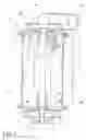
With reference to FIG. 2 showing a perspective view of the conventional sewage pump, the top cap 6, the upper bearing base, the tube body 8, the lower bearing base 10 and the lower base 11 are arranged from top to bottom to achieve the conventional sewage pump. Combinations between the top cap 6 and the upper bearing base 7, the upper bearing base 7 and the tube body 8, the tube body 8 and the lower bearing base 10, and the lower bearing base 10 and the lower base 11 are achieved by screws. The wire inlet 9 is for entrance of the wire to provide power from outside. The vertical bypass 12 connected between the lower inlet 111 on the lower base 11 and the upper outlet 63 on the top cap 6 so that sewage can be conducted into the sewage pump via the lower inlet 111, pumped through the vertical bypass 12 and then discharged out of the sewage pump via the upper outlet 63.
According to above description, the main shaft 2 is simply supported by the bearing 7 on the upper bearing base 7 and the bearing 102 on the lower bearing base 10 respectively at each end so that the supporting strength is insufficient and the motor 1 can not efficiently drive the main shaft 2 and actuate sewage-treating elements such as the upper impeller 3, the lower impeller and the grinder wheel 5. Therefore, treating efficiency of the conventional sewage pump is low. Moreover, the wire inlet 9 does not have any protection and the wire is easily damaged so that broken circuit or short circuit happens often. Additionally, because the main shaft 2 only has two rotary seal 71, 101 attached respectively at the two ends, sealing efficiency is poor and sewage probably permeates into the motor 1 or other driving elements. Without having any monitoring device such as moisture-sensors to signal water leakage and to timely stop the sewage pump, the motor 1 will malfunction.
SUMMARY OF THE INVENTIONAccording to above description, a modified sewage pump in the present invention is provided to overcome the drawbacks of the conventional sewage pump.
A main objective of the present invention is to provide a sewage pump that has quad-bearing structures on a main shaft to make the sewage pump excellent in supporting strength and durable at high speed operation.
Another main objective of the present invention is to provide a sewage pump that uses epoxy material to stuff a wire inlet connector on the sewage pump to further protect the wire and to prevent inadvertent damage caused by pulling or dragging.
Still another main objective of the present invention is to provide a sewage pump that has an internal moisture-sensor to monitor water leakage of the sewage pump and to timely stop the motor when the water leakage occurs.
To overcome the foregoing main objectives of the sewage pump in the present invention, the sewage pump comprises:
a motor providing the power and driving the sewage pump;
a main shaft penetrating the motor and having a top end combined with an upper impeller and a bottom end combined with a lower impeller and a grinding wheel;
a top cap served as a zenith of the sewage pump and having an upper inlet, an upper impeller chamber and an upper outlet;
an upper bearing with a mounting plate that combines with the top cap;
an upper bearing base attached under the mounting plate on the upper bearing to perform an upper seal chamber therebetween;
a tube body hermetically engaged under the upper bearing base, having a side face and a protrusion tube extending from the side face, and combining with a wire inlet connector;
a lower bearing base hermetically engaged under the tube body;
a lower bearing with a mounting plate attached to the lower bearing base to perform a lower seal chamber therebetween;
a lower base attached under the mounting plate on the lower bearing and having a lower inlet, a lower impeller chamber and a lower outlet; and
a vertical bypass communicated between the lower outlet on the lower base and the upper inlet on the top cap;
wherein, improvements of the sewage pump comprise:
the upper bearing with the mounting plate, the upper bearing base, the lower bearing base and the lower bearing with the mounting plate individually have a bearing portion to perform a quad-bearing structure on the main shaft to make the sewage pump stable and durable at high speed operation;
the upper bearing with the mounting plate, the upper bearing base, the lower bearing base and the lower bearing with the mounting plate individually have a rotary seal to make the sewage pump hermetical.
Further benefits and advantages of the present invention will become apparent after a careful reading of the detailed description with appropriate reference to the accompanying drawings.
BRIEF DESCRIPTION OF THE DRAWINGSFIG. 1 is a cross-sectional side view of a conventional sewage pump in accordance with the prior art;
FIG. 2 is a perspective view of the conventional sewage pump in FIG. 1;
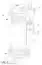
FIG. 3 is a cross-sectional side view of a sewage pump in accordance with the present invention; and
FIG. 4 is a perspective view of the sewage pump in FIG. 3.
DETAILED DESCRIPTION OF THE PREFERRED EMBODIMENTA sewage pump in accordance with the present invention comprises a motor, a main shaft, an upper impeller, a lower impeller, a grinding wheel, a top cap, an upper bearing base with a mounting plate, an upper bearing base, a tube body with a wire inlet connector, a lower bearing base, a lower bearing with a mounting plate, a lower base and a vertical bypass. Improvement of the sewage pump is that the main shaft has a quad-bearing structure and multiple rotary seals at ends to improve stability and sealing efficiency of the sewage pump. Moreover, the wire inlet connector is filled with epoxy material to protect the wire and the bearing bases have moisture-sensors to timely stop the motor when the rotary seals are failing and water is in seal chambers. Therefore, the sewage pump has excellent efficiency, stability and durability.
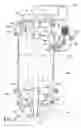
With reference to FIG. 3, the sewage pump of the present invention comprises a motor 13, a main shaft 14, an upper impeller 15, a lower impeller 16, a grinder wheel 17, a top cap 18, an upper bearing 19 with a mounting plate, an upper bearing base 20, a tube body 21, a wire inlet connector 22, a lower bearing base 23, a lower bearing 24 with a mounting plate, a lower base 25 and a vertical bypass 26. In the present sewage pump, the motor 13 is the power source to drive the main shaft 14. The main shaft 14 axially penetrates the motor 13 and has an upper end engaging the upper impeller 15 and a lower end engaging the lower impeller 16 and the grinder wheel 17, wherein the upper impeller 15, the lower impeller 16 and the grinder wheel 17 are grinding elements. The top cap 18 mounts on a zenith of the sewage pump and has an upper inlet 181, an upper impeller chamber 182, an upper outlet 183 and a screw 184, wherein the top cap 18 attaches to the upper bearing base 19 with the mounting plate by the screw 18 and the upper impeller chamber 182 accommodates the upper impeller 15. The upper bearing 19 with the mounting plate is one-pieced and has a rotary seal 191 and a screw 192 that combines the upper bearing 19 with the upper bearing base 20 and then constructs an upper seal chamber (not numbered). A moisture-sensor 204 attached on the upper bearing base 20 inside the seal chamber to signal if sealing efficiency of the upper seal chamber is failing. The upper bearing base 20 has a gasket 201, a bearing 202 and a screw 203 that combines the upper bearing base 20 with the tube body 21. The tube body 21 is a middle section of the sewage pump and combines the lower bearing base 23 by a screw 212. The tube body 21 further has a protrusion tube 211 formed on a side face and combines with the wire inlet connector 22 by a screw 222 at the protrusion tube 211. The wire inlet connector 22 serves as entrance of wire and contains epoxy filling material inside. The lower bearing base 23 has a rotary seal 231, a bearing 232 and a moisture-sensor 233 and is combined with the lower bearing base 24 by a screw 234 at the mounting plate. The lower bearing 24 with the mounting plate is one-pieced bearing and has a rotary seal 241 inside and combines with the lower base 25 by a screw 242 to perform a lower seal chamber (not numbered) that accommodates the moisture-sensor 233. The lower base 25 is a bottom of the sewage pump and has a lower inlet 251, a lower impeller chamber 252 and a lower outlet 253 communicated with the vertical bypass 26. The vertical bypass 26 is a tube connecting the lower base 25 and the top cap 18 to communicate with the lower outlet 253 on the lower base 25 and the upper inlet 181 on the top cap 18 respectively at two ends.
By having the above elements, sewage is conducted into the sewage pump via the lower inlet 251 on the lower base 25, grinded by the grinding wheel 17 and the lower impeller 16 in the lower impeller chamber 252 and then conducted to the vertical bypass 26 via the lower outlet 253. Then, the sewage is conducted to the top cap 18 via the upper inlet 181 and into the upper impeller chamber 182 to further increase pressure and be discharged out of the sewage pump via the upper outlet 183.
The upper bearing 19 with the mounting plate, the upper bearing base 20, the lower bearing base 23 and the lower bearing 24 with the mounting plate each have a bearing structure and a rotary seal to increase supporting strength to the main shaft 14 and sealing efficiency. Therefore, the motor 13 enables to drive the main shaft 14 with the upper impeller 15, the lower impeller and the grinding wheel 17 at high speed to minimize shaft deflection and to make the sewage minimized in size to meet the discharge standard.
By packing the epoxy filling material 221 into the wire inlet connector 22, protection of the wire is enhanced.
By having moisture-sensors 204, 233 in the upper and lower seal chamber of the sewage pump, the moisture-sensors 204, 233 signal water leakage of the sewage pump and then stops the motor 13 when the water is in the upper and lower seal chambers and the seal efficiency is failing.
With reference to FIG. 4 showing a perspective view of the sewage pump of the present invention, the top cap 18, the upper bearing 19 with the mounting plate, the upper bearing base 20, the tube body 21, the lower bearing base 23, the lower bearing 24 with the mounting plate and the lower base 25 are arranged from top to bottom to achieve the present sewage pump. Combinations of the top cap 18 and the upper bearing 19 with the mounting plate, the upper bearing 19 with mounting plate and the upper bearing base 20, the upper bearing base 20 and the tube body 21, the tube body 21 and the lower bearing base 23, and the lower bearing base 23 and the lower bearing 24 with the mounting plate, and the lowering bearing 24 with the mounting plate and the lower base 25 are all achieved by screws. The wire inlet connector 22 is for entrance of the wire to provide power from outside. The vertical bypass 26 connected between the lower inlet 251 on the lower base 25 and the upper outlet 183 on the top cap 18 so that sewage can be conducted into the sewage pump via the lower inlet 251, pumped through the vertical bypass 26 and then discharged out of the sewage pump via the upper outlet 183.
According to above description, improvement of the sewage pump in the present invention is to enhance the supporting stability at high speed operation by having dual-bearing structures at two ends of the main shaft 14. Moreover, the rotary seals 191, 241 and epoxy filling material packed inside the wire inlet connector 22 isolate the sewage from the motor 13 to protect the motor 13. The moisture-sensor 233 also ensures the operation of the motor 13 safe in the sewage pump.
Although this invention has been described in its preferred form with a certain degree of particularity, it is understood that the present invention of the preferred form has been made only by way of example and that numerous changes in the details of construction and the combination and arrangement of parts any be resorted to without departing from the spirit and scope of the invention.
Claims
What is claimed is:1. A sewage pump comprising:
a motor providing the power and driving the sewage pump;
a main shaft penetrating the motor and having a top end combined with a upper impeller and a bottom end combined with a lower impeller and a grinding wheel;
a top cap served as a zenith of the sewage pump and having an upper inlet, an upper impeller chamber and an upper outlet;
an upper bearing with a mounting plate that combines with the top cap;
an upper bearing base attached under the mounting plate on the upper bearing to perform an upper seal chamber;
a tube body hermetically engaged under the upper bearing base, having a side face and a protrusion tube extending from the side face, and combining with a wire inlet connector;
a lower bearing base hermetically engaged under the tube body;
a lower bearing with a mounting plate attached to the lower bearing base to perform a lower seal chamber;
a lower base attached under the mounting plate on the lower bearing and having a lower inlet, a lower impeller chamber and a lower outlet; and
a vertical bypass communicated between the lower outlet on the lower base and the upper inlet on the top cap;
wherein, improvements of the sewage pump comprise:
the upper bearing with the mounting plate, the upper bearing base, the lower bearing base and the lower bearing with the mounting plate individually have a bearing portion to perform a quad-bearing structure on the main shaft to make the sewage pump stable and durable at high speed operation;
the upper bearing with the mounting plate, the upper bearing base, the lower bearing base and the lower bearing with the mounting plate individually have a rotary seal to make the sewage pump hermetical.
2. The sewage pump as claimed in claim 1, wherein the wire inlet connector is filled with epoxy filling material.
3. The sewage pump as claimed in claim 1, wherein the lower bearing base further comprises a moisture-sensor that electrically connects to the motor and operationally stop the motor when water is in the lower seal chamber and sealing efficiency of the lower seal chamber is failing.
4. The sewage pump as claimed in claim 3, wherein the upper bearing base further comprises a moisture-sensor that electrically connects to the motor and operationally stop the motor when water is in the upper seal chamber and sealing efficiency of the upper seal chamber is failing.
5. The sewage pump as claimed in claim 1, wherein combination of the top cap and the upper bearing with the mounting plate, the upper bearing with mounting plate and the upper bearing base, the upper bearing base and the tube body, the tube body and the lower bearing base, and the lower bearing base and the lower bearing with the mounting plate, and the lowering bearing with the mounting plate and the lower base are achieved by screws.
Images & Drawings included:
Sources:
- United States Patent and Trademark Office - verify current appl. status at the USPTO↗
Similar patent applications:
- » 20150345505
Casing liner for sewage pump and sewage pump with the same - » 20090162219
Sewage Pump - » 20080159876
PROTECTIVE DEVICE FOR A CONTROLLING SYSTEM OF A SEWAGE PUMP - » 20070072538
Modular vent assembly for a sewage pumping station - » 20080095630
BLADE WHEEL FOR A SEWAGE PUMP - » 20080158743
Protective device for a controlling system of a sewage pump - » 10461810
Centrifugal sewage pumps with two impellers - » 20080219857
PROTECTIVE DEVICE FOR A CONTROLLING SYSTEM OF A SEWAGE PUMP - » 20090067992
Sewage pump - » 20090087317
Blade set for masserating effluent water in a sewage pump
Recent applications in this class:
- » 20250116274 2025-04-10
HIGH EFFICIENCY DRILLING FLUID SHEARING PUMP USING STAGED TESLA TURBINE - » 20240328422 2024-10-03
PUMP CASING AND PUMP - » 20240011497 2024-01-11
PUMP FOR IMMERSION WITHIN A FLUID RESERVOIR - » 20230296098 2023-09-21
Cutting Blade Assembly - » 20230287888 2023-09-14
Pump apparatus for reducing the size of suspended solids before pumping - » 20230258188 2023-08-17
Non-clogging pump - » 20220145890 2022-05-12
Cutting system for a grinding pump and related grinding pump - » 20220065254 2022-03-03
Cutting assembly for a chopper pump - » 20210148365 2021-05-20
Reversing grinder pump - » 20200291944 2020-09-17
Cutting blade assembly