Apparatus and method for assembling a balustrade system
US20070102690A1
2007-05-10
11/269,306
2005-11-07
Abstract:
An apparatus and method for assembling ad balustrade system. The balustrade system comprising one or more primary members. One or more toroido-cylindrical shaped nodal rings are secured to the primary member. One or more socket fittings are secured to one toroido-cylindrical shaped nodal ring. Each socket fitting defines a socket bore. A secondary member is secured within the socket bore.
Interested in similar patents?
Get notified when new applications in this technology area are published.
Classification:
E04F11/1812 » CPC main
Stairways, ramps, or like structures ; Balustrades; Handrails; Balustrades; Handrails; Balustrades Details of anchoring to the wall or floor
E04F11/1814 » CPC further
Stairways, ramps, or like structures ; Balustrades; Handrails; Balustrades; Handrails; Balustrades; Details of anchoring to the wall or floor Covers for the base portions of the balustrade posts
E04F19/02 » CPC further
Other details of constructional parts for finishing work on buildings Borders; Finishing strips, e.g. beadings; Light coves
E04H17/14 IPC
Fencing, e.g. fences, enclosures, corrals Fences constructed of rigid elements, e.g. with additional wire fillings or with posts
Description
FIELD OF THE INVENTIONThis invention relates to construction systems for the provision of railings, fencing, balustrading or the like. In particular the invention relates to construction systems which are pre-fabricated and installed on-site.
BACKGROUNDIn the provision of railings, fencing, balustrading or the like, it is common for more or less horizontal railing members to be welded to stanchion members on-site, with the welded parts subsequently being ground smooth and polished. Welded assembly is the most common construction method where components are made from stainless steel, as is the case in many architectural applications. Hand welding of stainless steel is a skilled process which adds to the installed cost of railings or balustradings and frequently results in unsightly local heat distortion of welded components. Lower cost construction systems in which structural components are simply bolted or clamped together are well known in the art, but these are frequently aesthetically unattractive. As a result, they are unsuited for many architectural applications.
Where railing and balustrading construction systems incorporate aesthetically attractive joining means, these usually involve the employment of specially manufactured, expensive components. In some examples, generally cylindrical joint members are employed to join stanchion and rail members. The joint members are complex in shape, clearly expensive to manufacture, are somewhat limited in the structural arrangements which they permit and, from an aesthetic standpoint, appear somewhat mechanical.
In other examples, specially manufactured, shanked fittings are permanently fixed to stanchions with suitable fastenings and the ends of rail members are slipped over the shanks of the fittings. The internal and external diameters, respectively, of the rail members and shanks are such as to provide a neat sliding fit and the ends of the rail members are retained in place on the shanks by the wedging action of O-rings accommodated in suitably shaped, tapered grooves in the shanks. While this arrangement provides some ease of assembly, in some applications, long-term hardening and deterioration of the O-rings as a result of temperature extremes may be expected with a possible loss of structural integrity. Additionally, where they are required, intermediate vertical rails between upper and lower horizontal rails are still required to be welded into place. The arrangement thus does not properly fill the need for a relatively low cost, easily assembled, permanent structure.
Consequently, there is a need for a cost-effective balustrade system which allows on-site assembly without the need for welding.
SUMMARYThe present invention is a balustrade system which allows on-site assembly without welding and a method for assembling the balustrade system.
In one embodiment, the balustrade system comprises one or more primary members. One or more toroido-cylindrical shaped nodal rings are secured to the primary member. One or more socket fittings are secured to one toroido-cylindrical shaped nodal ring. Each socket fitting defines a socket bore. A secondary member is secured within the socket bore.
In one embodiment of an apparatus for connecting the primary and secondary members of the balustrade system, the apparatus comprising a toroido-cylindrical shaped nodal ring. The toroido-cylindrical shaped nodal ring is adapted to be positioned on the primary member. The apparatus also comprises one or more socket fittings adapted to receive a secondary member and a means for engaging the toroido-cylindrical shaped nodal ring with the socket fitting.
In one embodiment of a method for assembling the balustrade, the method comprises positioning a toroido-cylindrical shaped nodal ring onto a primary member and securing the toroido-cylindrical shaped nodal ring to the primary member. The method also comprises securing a socket fitting to the toroido-cylindrical shaped nodal ring and securing a secondary member within a socket bore defined by the socket member.
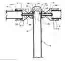
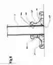
BRIEF DESCRIPTION OF THE DRAWINGSFIG. 1 is a view of a nodal assembly fixed at an intermediate position on a stanchion member;
FIG. 2 is a longitudinal cross-sectional view of a nodal assembly and cap fitting fixed at the top of a stanchion member;
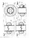
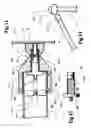
FIG. 3 is a longitudinal cross-sectional view of alternative means of fixing a toroido-cylindrical shaped nodal ring to a stanchion member;
FIG. 4 is a longitudinal cross-sectional view of the toroido-cylindrical shaped nodal ring depicted at FIG. 3 fixed to a stanchion member using alternative means;
FIG. 5 is a transverse cross-sectional view of the arrangement depicted at FIG. 4;
FIG. 6 is a longitudinal cross-sectional view of further alternative means of fixing a toroido-cylindrical shaped nodal ring to a stanchion member;
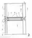
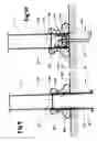
FIG. 7 is a side view of panel members supported between adjacent stanchion members;
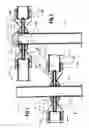
FIG. 8 is a longitudinal cross-sectional view of further alternative means of fixing stanchion members to a supporting surface;
FIG. 9 is a longitudinal cross-sectional view of means of fixing stanchion members to a supporting surface;
FIG. 10 is a longitudinal cross-sectional view of alternative means of fixing stanchion members to a supporting surface;
FIG. 11 is a longitudinal cross-sectional view of alternative means of fixing socket fittings to toroido-cylindrical shaped nodal rings;
FIG. 12 is a side view of the fastener forming part of the means depicted at FIG. 11;
FIG. 13 is a partial side view of an alternative arrangement of rail and stanchion members.
DETAILED DESCRIPTIONReferring now to FIG. 1, one embodiment of the balustrade system is depicted. The balustrade system includes one or more primary members. As shown, the primary member of the balustrade system is a more or less vertically arranged stanchion member 1. One or more toroido-cylindrical shaped nodal rings 2 are positioned on the primary member. The shape of the nodal ring is more or less that of a toroid from which material has been removed internally to create a cylindrical bore 3 passing through the full thickness of the toroid and collinear with its axis, the diameter of the bore being such as to provide an easy sliding fit on the stanchion member.
One or more suitably positioned, radially-arranged, extended grub screws 4 are screwed into threaded bores 8 provided in the nodal rings and, when tightened with a suitable tool engaging shaped recess 9, act to lock the nodal ring securely to the stanchion member.
O-rings (not shown) of a suitable material are accommodated in grooves 5 provided in bore 3 and act to provide a resilient bearing surface between the surface of cylindrical bore 3 and the external surface of stanchion member 1, thereby preventing the nodal ring from marring the polished external surface of the stanchion member.
One or more socket fittings 6 are secured to one toroido-cylindrical shaped nodal ring 2 by a means for engaging the toroido-cylindrical shaped nodal ring to the socket fitting 6. Each socket fitting defines a socket bore 11 adapted to receive a secondary member.
In one embodiment, the means for engaging the toroido-cylindrical shaped nodal ring to the socket fitting is a threaded extension of the grub screws 4, which extends beyond the external surface of the nodal ring. The threaded socket bores 10 of socket fittings 6 are screwed onto the threaded extensions and tightened using a non-marring, strap-type wrench of leather or textile material. The threaded socket bores are made collinear with the longitudinal axes of the socket fittings.
The ends of a secondary member 7, in this case a rail, are accommodated within the socket bores 11 of the socket fittings and O-rings (not shown) of a suitable material are accommodated in grooves 12 provided in the socket bores 11. The O-rings act to provide a resilient bearing surface between the surface of the socket bore 11 and the external surfaces of the secondary members 7, thereby preventing the nodal ring from marring the polished external surface of the rail members.
In alternative embodiment, a suitable adhesive compound, such as two-part epoxy adhesive, is employed to bond the nodal rings and the socket fittings, respectively to the primary members and the secondary members.
In one embodiment, the end surface of the socket fitting abutting the nodal ring is made flat and a complementary flat surface is provided on the external surface of the nodal ring. In an alternative embodiment (depicted as 29 in FIG. 8) the end surface of the socket fitting is provided with a shape complementary to that of the external surface of the nodal ring.
In a further embodiment, suitable solid or substantially solid, close-fitting plugs (not shown) are provided in the the primary members to support the primary members against collapsing forces applied by the grub screws.
For the purpose of general description, the term, primary member, may be taken to mean a member of larger diameter to which a member of smaller diameter, a secondary member, is fixed. In the preceding explanation, the stanchion members are primary members and the rail members are secondary members. In more complex arrangements, the rail members may, in turn, become primary members and have fixed to them tertiary members, such as a cross rail.
Referring now to FIG. 2, a nodal arrangement similar to that depicted in FIG. 1 is provided at the top of stanchion member 1. A plug-type cap 13 is provided to close the upper end of the stanchion member, cylindrical shank 14 of the cap forming a neat sliding fit with cylindrical bore 3 of nodal ring 2 and the cap being secured in place on the nodal ring by one or more grub screws 16 being screwed into threaded bores 15 provided in the cylindrical shank and tightened to engage upper O-ring groove 5. The cap may be fixed to the nodal ring prior to its positioning on the stanchion member.
While the nodal ring must retain the toroido-cylindrical shape, the socket fitting and the cap may be shaped in any desired way to meet the aesthetic requirements of a railing or balustrade installation.
In another embodiment the cylindrical shank of the cap fitting may be made solid or substantially solid and sufficiently long to extend into the bore of the stanchion member beneath a the nodal ring positioned at the top of the stanchion member and, by making a close fit with the inner surface of the stanchion member, to support the stanchion member against collapsing forces applied by the grub screws.
With reference to FIGS. 3, 4 and 5, alternative means are provided to lock nodal rings 2 to stanchion members 1 in situations in which the extended grub screws cannot be used. In a first means, apertures 17 are provided in the stanchion member and a circumferential groove 18 is provided in the cylindrical bore 3 of the nodal ring. A locking bar 20 is elastically distorted to allow it to enter the bore 19 of the stanchion member and is positioned using a suitable extended tool such that its ends 21 extend elastically through the apertures 17 and into the circumferential groove 18. The locking bar can be made from an elastic metal, such as spring steel, and is provided along part of its length with convolutions which facilitate its elastic deformation. The corners of the ends of the locking bar are preferably formed into points which engage the surface of circumferential groove 18, thereby acting to prevent rotation of the nodal ring on the stanchion member. Removal of the locking bar using a suitable extended tool permits the nodal ring to be removed from the stanchion member.
With reference to FIG. 6, further alternative means are provided to lock nodal rings 2 to stanchion members 1 in situations in which the extended grub screws cannot be used. In this arrangement, one or more small grub screws 22 are screwed into the threaded bores 23 provided in and passing more or less radially through the nodal ring. When tightened, the grub screws 22 engage the stanchion member 1 and lock the nodal ring to it. In one embodiment, the threaded bores angle upwardly from the lower surface of the nodal ring. In this position the bores are minimally conspicuous. In alternative embodiments, the threaded bores are positioned anywhere on the nodal rings.
With reference to FIG. 7, provision is made for panel members 24 to be supported between adjacent stanchion members 1. Stanchion members 1 are fixed to supporting surface 27 with fixing means including dress piece 28 and assembled to rail members 25 in the manner previously described. Additionally, the nodal rings 2 are fixed to the stanchion members 1 in intermediate positions and panel supporting members 26 are fixed to the additional nodal rings using suitable flush fastenings. In the preferred embodiment, the panel supporting members 26 take the form of a more or less square channel made from a suitable material and are lined with a suitable resilient material to positively grip the edges of the panel members. The panel supporting members 26 are closed at their lower ends to retain the panel members 24 within them. In an alternative embodiment, the panel supporting members 26 are fixed directly to the stanchion members 1. The panel members 24 may be made from any suitable material.
With reference to FIG. 8, means are provided to fix the stanchion member to a supporting surface. In this arrangement, stanchion member 1 is fixed to mounting flange 63 by one or more mounting bore grub screws screwed into threaded holes 66 provided in the mounting flange 63. In one embodiment, O-rings (not shown) are accommodated in suitable grooves 65, 70 provided in mounting bore 64 of the mounting flange 63 to prevent the mounting flange 63 from marring the polished external surface of the stanchion member. The mounting flange 63 is, in turn, fixed to the supporting surface by suitable fastenings (not shown) passing through attachment holes 67 provided in the mounting flange. In an alternative embodiment (not shown), the mounting flange 63 is provided with a deep chamfer or other circumferential recess at point 68 and the end of the stanchion member is fixed to the mounting flange by welding into the chamfer or circumferential recess, such that the welding bead does not obtrude from and prevent the seating of the mounting flange 63 on the supporting surface.
With reference to FIG. 9, alternative means are provided to fix the stanchion members to a supporting surface. In the simplest embodiment, the stanchion members 1 are simply cast into the supporting surface, supported in correct alignment by suitable means until the concrete or other material from which the supporting surface is made has properly set.
In one embodiment, an anchor tube 35 is cast into the supporting surface, supported in correct alignment by suitable means until the concrete or other material from which the supporting surface is made has properly set. A flange 40 is provided on the lower end of the anchor tube 35 to better secure the anchor tube in the supporting surface. The lower end 34 of the stanchion memeber is inserted into the anchor tube 35 for a suitable distance, the diameters of their complementary surfaces being such as to make a tight sliding fit. One or more pairs of corresponding holes 48 are drilled through the anchor tube 35 and the stanchion member 1 and roll pins 36 or other suitable fastenings are driven or inserted through them to fix the stanchion member 1 to the anchor tube 35. A dress piece 28 is placed on and positioned at the bottom of the stanchion member and secured in place by a locking bar 39 inserted as described in relation to FIGS. 3, 4 and 5 through opposed apertures 37 in the stanchion member to engage groove 38 provided in the dress piece. In one embodiment, an O-ring (not shown) is accommodated in a suitable groove (not shown) provided in the upper part of the dress piece to prevent the dress pieces from marring the polished external surfaces of the stanchion member. In an alternative embodiment, the dress piece 28 is fixed to the base of the stanchion member using grub screws as described in relation to FIG. 6. In an alternative embodiment, the anchor tube 35 may be made smaller in diameter and the stanchion member 1 positioned over its exterior.
With reference to FIG. 10, further alternative means are provided to fix the stanchion members to a supporting surface. In this arrangement, anchor bolt 43 is cast into supporting surface 27 and a mounting boss 41 secured to threaded upper part 45 of the anchor bolt 43 by the tightening of suitable nut 46. In one embodiment, a lug 44 is provided on the lower end of the anchor bolt 43 to better secure the anchor bolt in the supporting surface. The lower end 34 of the stanchion tube is positioned over the mounting boss 41 with its end surface abutting flange 42 provided at the bottom of the mounting boss 41, the diameters of their complementary surfaces being such as to make a tight sliding fit. One or more pairs of corresponding holes 47 are drilled through the anchor tube and the mounting boss and roll pins 36 or other suitable fastenings are driven or inserted through them to fix the stanchion member to the mounting boss. Dress piece 28 is placed on and positioned at the bottom of the stanchion member and secured in place by a locking bar 39 inserted as described in relation to FIG. 9. In one embodiment, an O-ring (not shown) is accommodated in a suitable groove (not shown) provided in the upper part of the dress piece to prevent the dress piece from marring the polished external surface of the stanchion member. In an alternative embodiment, the dress piece is fixed to the base of the stanchion member using grub screws as described in relation to FIG. 6.
With reference again to FIGS. 1 and 2, where a horizontal rail member 7 is to be fixed between two stanchion members 1 in fixed positions, it is cut to a length such that, with its ends fully inserted into socket bores 11 of socket fittings 6, the outer ends of the socket fittings can just be accommodated between the ends of grub screws 4 screwed into nodal rings 2. The socket fittings 6 are slid outwardly on the horizontal rail member to introduce the ends of the grub screws into threaded socket bores 10 of the socket fittings 6 and the socket fittings 6 are turned to engage the threaded socket bores 10 and screw the socket fittings fully and tightly onto the socket fittings.
With reference to FIGS. 11 and 12, alternative means are provided to fix a the horizontal rail member between two the stanchion members in fixed positions. In this embodiment, nodal rings 2 are secured to stanchion members 1 by one or more grub screws 62 in the manner previously described. The grub screws 62 are of a length such that they protrude only slightly from the nodal ring when tightened. Counter bores 49 are provided in the nodal ring around the grub screws 4.
In one embodiment, the counter bores 49 extend through approximately half the depth of the nodal ring. A bolt bore 51 is provided through socket fitting 6 collinear with its longitudinal axis. The bolt bore 51 can be provided with one or more splines, keys or other locating means 53. Hollow bolt 52 passes freely through bolt bore 51 of the socket fitting 6, but the hollow bolt 52 is constrained from independent rotational movement in relation to the socket fitting by complementary locating means 54 provided on the outer shank of the hollow bolt. The hollow bolt is provided with a threaded interior bore 55 which is adapted to be screwed over that part of the grub screw exposed within counterbore 49, causing plain inner shank 56 of the hollow bolt to enter the counterbore.
A spring retaining pan 59 made from a suitable light material is pressed into horizontal rail member 7 and retained by friction. The head 57 of the hollow bolt is provided with spring locating boss 58 and bolt projection spring 61 is located between the spring locating boss and a similar boss 60 formed on the spring retaining pan. In use, the nodal ring is secured to the stanchion member by screwing one or more the grub screws 62 into threaded bores 8 and tightening them against the stanchion member. The hollow bolt 52 is pushed back into the socket fitting 6 against the urging of the bolt projection spring 61 and the end of the socket fitting 29 aligned with the grub screw, permitting the hollow bolt to index with the outer end of the grub screw. The socket fitting 6 is then turned to screw the hollow bolt 52 onto the grub screw 62, the hollow bolt being tightened against the nodal ring using a non-marring, strap-type wrench of leather or textile material to turn the socket fitting.
Where the socket fitting 6 is to be fixed to a fixing surface other than a stanchion member, attachment means in the form of a double-ended bolt (not shown) are employed. One part of the double-ended bolt is provided with a coarse, tapered thread similar to that of a coach bolt. The other part of the double-ended bolt is provided with a conventional parallel thread complementary with that of the socket fitting. A flatted, medial collar is provided between the two the threaded parts. In use, the tapered threaded part of the bolt is screwed and tightened into a suitable bore in the fixing surface, being turned by means of a suitable tool applied to the flatted collar. The socket fitting is then screwed and tightened onto the parallel threaded part in the manner previously described.
With reference to FIG. 13, rail member 7 is fixed to nodal ring 2 at an angle. This is achieved simply by providing threaded bores 8 in the nodal ring at a suitable angle and then assembling the components in the manner previously described.
In all cases in which a the nodal ring 2 is fixed to a the stanchion member using one or more the grub screws, a support piece (not shown) made from a short length of thick-walled tubing or solid cylinder of a suitable hard material having an external diameter slightly less than that of the stanchion member is inserted into the interior of the stanchion member to support the stanchion member and prevent its collapse inwardly as a result of the high, localized force generated by the grub screws.
In the method of the present invention, the method of assembling a balustrade system comprises the steps of: positioning a toroido-cylindrical shaped nodal ring 2 onto a primary member 1; securing the toroido-cylindrical shaped nodal ring 2 to the primary member 1; securing a socket fitting 6 to the toroido-cylindrical shaped nodal ring 2; and securing a secondary member 7 within a socket bore 11 defined by the socket member 6. The method can included forming the socket fitting in a decorative shape.
In the one embodiment of the method (as shown in FIG. 4), the toroido-cylindrical shaped nodal ring 2 can be secured to the primary member 1 by placing a locking bar 20 within the primary member and engaging the ends of the locking bar 21 with a circumferential groove 18 defined by the toroido-cylindrical shaped nodal ring 2. To do this, the locking bar is passed through one or more apertures defined by the primary member.
In another embodiment of the method (as shown in FIG. 1 ),the toroido-cylindrical shaped nodal ring 2 can also be secured to the primary member 1 by tightening one or more grub screws 4 against the primary member 1. The grub screws 4 are accommodated within one or more threaded bores defined in the toroido-cylindrical shaped nodal ring.
In one embodiment, the method further comprises the step of securing the socket fitting 6 to the toroido-cylindrical shaped nodal ring 2 by engaging a threaded socket bore 10 defined by the socket fitting 6, with threaded extension of the grub screw 4 extending beyond the toroido-cylindrical shaped nodal ring.
In another embodiment, the method further comprises the step of protecting the surface of the primary member by fitting one or more O-rings within a groove 5 defined by the toroido-cylindrical shaped nodal ring 2. This is done so that the O-ring frictionally retains the toroido-cylindrical shaped nodal ring 2 in place during assembly.
In yet another embodiment depicted in FIGS. 7, 8, 9, and 10, the method further comprises the step of fixing an end of the primary member 1 to a supporting surface 27. This method can comprise fitting a dress piece 28 around the primary member 1. The dress piece 28 defines one or more threaded dress piece bores. The dress piece is abutted to the supporting surface 27 and secured to the primary member 1 with one or more dress piece grub screws extending through the threaded dress piece bores. The primary member 1 can be fixed to the support surface 27 by casting the end of the primary member into the support surface.
The primary member can also be fixed to the support surface 27 by casting an anchor tube 35 into the support surface 27. The primary member 1 slides into the anchor tube 35 and is secured to the anchor tube 35 by engaging a fastening means through both the primary member 1 and the anchor tube 35.
Alternatively, the primary member can be fixed to the support surface by casting an anchor bolt 43 into the supporting surface 27. A mounting boss 41 is secured to the anchor bolt 43 by tightening a nut 46. The mounting boss 41 is secured to the primary member 1 by engaging a fastening means through both the primary member and the mounting boss.
Finally, the primary member 1 can be fixed to the support surface 27 by fastening a mounting flange 63 to the support surface 27. The mounting flange 63 comprises a mounting bore 64 adapted to form a sliding fit around the primary member 1. The mounting bore 64 defines one or more threaded holes 66. The primary member is placed in the mounting flange. One or more mounting bore grub screws are engaged with the exterior surface of the primary member 1. The mounting bore grub screws are positioned in the threaded holes 66.
In a final embodiment of the method, the method comprises securing a second socket fitting to a fixing surface with a double ended bolt. One end of the secondary member is secured within the second socket fitting. Examples of suitable fixing surfaces include a wall and a beam.
Claims
1. An apparatus for connecting the primary and secondary members of a balustrade system, the apparatus comprising:
a toroido-cylindrical shaped nodal ring, the toroido-cylindrical shaped nodal ring adapted to be positioned on a primary member;
one or more socket fittings adapted to receive a secondary member; and
a means for engaging the toroido-cylindrical shaped nodal ring with the socket fitting.
2. The apparatus of claim 1 wherein the means to engage the toroido-cylindrical shaped nodal ring with the socket fitting comprises one or more grub screws, the toroido-cylindrical shaped nodal ring having one or more threaded bores and the one or more grub screws accommodated within the threaded bores to lock the toroido-cylindrical shaped nodal ring to the primary member, the grub screw comprising a threaded extension extending beyond the toroido-cylindrical shaped nodal ring.
3. The apparatus of claim 2 wherein the socket fitting comprises a threaded socket bore, the threaded socket bore engageable with the threaded extension of the grub screw.
4. The apparatus of claim 1 wherein the toroido-cylindrical shaped nodal ring defines a cylindrical bore collinear with the toroido-cylindrical shaped nodal ring's axis.
5. The apparatus of claim 4 wherein the cylindrical bore has a diameter sized to provide an easy sliding fit on the primary member.
6. The apparatus of claim 4 wherein the toroido-cylindrical shaped nodal ring defines one or more grooves in the cylindrical bore and one or more O-rings are positioned in the grooves.
7. The apparatus of claim 1 wherein the primary member is a stanchion and the secondary member is a rail.
8. The apparatus of claim 1 wherein the primary member is a rail and the secondary member is a cross rail.
9. The apparatus of claim 1 wherein the diameter of the socket bore is sized to provide an easy sliding fit with the secondary member.
10. The apparatus of claim 1 wherein the apparatus further comprises one or more plugs positioned inside the primary members to support the primary members against the collapsing forces applied by said grub screws.
11. The apparatus of claim 1 wherein the socket fitting comprises a cylindrically-shaped portion containing the socket bore and a conically-shaped portion containing the threaded socket bore.
12. The apparatus of claim 11 wherein the conically-shaped portion comprises an end surface distal to the cylindrically-shaped portion, the end surface shaped to complement the shape of the toroido-cylindrical shaped nodal ring.
13. The apparatus of claim 1 wherein the socket fitting defines one or more grooves in the socket bore and one or more O-rings are positioned in the grooves.
14. The apparatus of claim 1 comprising a plug-type cap adapted to close off an end of a primary member, the cap comprising a hollow cylindrical shank conformed to slidably fit within the cylindrical bore of a the toroido-cylindrical shaped nodal ring, the cylindrical shank secured in place within the cylindrical bore by one or more grub screws
15. The apparatus of claim 1 comprising a plug-type cap adapted to close off an end of a primary member, the cap comprising a substantially solid cylindrical shank conformed to slidably fit within the cylindrical bore of a the toroido-cylindrical shaped nodal ring, the substantially solid cylindrical shank sufficiently long to extend into the primary member, and adapted to be secured in place within a bore of the primary member by one or more grub screws to support the primary member against collapsing forces applied by said grub screws.
16. An apparatus for connecting the primary and secondary members of balustrade system, the apparatus comprising:
a toroido-cylindrical shaped nodal ring, the toroido-cylindrical shaped nodal ring adapted to be positioned on a primary member;
the toroido-cylindrical shaped nodal ring having one or more threaded bores;
one or more grub screws accommodated within the threaded bores to lock the toroido-cylindrical shaped nodal ring to the primary member, the grub screw comprising a threaded extension extending beyond the toroido-cylindrical shaped nodal ring;
one or more socket fittings having a threaded socket bore, the threaded socket bore attachable with the threaded extension of the grub screw; and
the socket fitting comprising a socket bore, the socket bore adapted to engage the secondary member, so that the secondary member is connectable to the primary member.
17. The apparatus of claim 16 wherein the threaded bores are radially arranged on the toroido-cylindrical shaped nodal ring.
18. The apparatus of claim 16 wherein the threaded bores are positioned at an angle to a plane normal to the primary member.
19. A balustrade system comprising:
one or more primary members;
one or more toroido-cylindrical shaped nodal rings secured to the primary member;
one or more socket fittings secured to one toroido-cylindrical shaped nodal ring, each socket fitting defining a socket bore; and
one or more secondary members, an end of the secondary member secured within the socket bore.
20. The system of claim 19 wherein the system further comprises one or more locking bars inserted in the primary member and one or more circumferential grooves defined inside the toroido-cylindrical shaped nodal ring, the locking bar passing through one or more apertures defined in the primary member and engaging with the circumferential groove.
21. The system of claim 20 wherein the locking bar is elastically deformable to allow the locking bar to be removable.
22. The system of claim 20 wherein the locking bar comprises a first end and a second end, wherein the first end and second end are formed into points, the points engageable with the surface of the circumferential groove to prevent toroido-cylindrical shaped nodal ring from rotating on the primary member.
23. The system of claim 19 wherein the system further comprises one or more grub screws accommodated within one or more threaded bores defined by the toroido-cylindrical shaped nodal ring, so that the grub screws are capable of securing the toroido-cylindrical shaped nodal ring to the primary member.
24. The system of claim 19 wherein the system further comprises an adhesive substance adapted to secure the toroido-cylindrical shaped nodal ring to the primary member.
25. The system of claim 19 wherein the system further comprises an adhesive substance adapted to secure the socket fitting to the toroido-cylindrical shaped nodal ring.
26. The system of claim 19 wherein the system further comprises one or more panels and one or more supporting members secured to the toroido-cylindrical shaped nodal ring, the supporting member defining a channel adapted to receive the panel.
27. The system of claim 19 wherein the system further comprises:
one or more grub screws accommodated within one or more threaded bores defined by the toroido-cylindrical shaped nodal ring, the grub screws comprising a threaded extension extending outward from the toroido-cylindrical shaped nodal ring; and
the socket fitting defining a threaded socket bore, the threaded socket bore engaging with the threaded extension of the grub screw.
28. The system of claim 27 wherein the system further comprises:
one or more hollow bolts;
the hollow bolts defining a threaded interior bore;
the socket fitting defining a bolt bore;
the hollow bolt passing through the bolt bore;
the toroido-cylindrical shaped nodal ring defining one or more counterbores collinear with the threaded bore of the toroido-cylindrical shaped nodal ring, the counterbores having a depth less than the threaded bore, the counterbore adapted to receive the hollow bolt; and
the hollow bolt positioned in the counterbore and the threaded interior bore of hollow bolt engaging the grub screw, so that the hollow bolt secures the socket fitting to the toroido-cylindrical shaped nodal ring.
29. The system of claim 28 wherein the bolt bore comprises one or more splines and hollow bolt comprises one or more grooves engaging the splines, so that the hollow bolt is prevented from rotating independently of the socket fitting.
30. The system of claim 28 wherein the system further comprises:
a spring retaining pan positioned in the secondary member, the spring retaining pan comprising a first spring locating boss;
the hollow bolt comprising a head, the head comprising a second spring locating boss; and
a bolt projection spring, the bolt projection spring positioned between first spring retaining boss and the second spring retaining boss, so that the spring forces the hollow bolt to contact the grub screw when the secondary member is joined with the socket fitting.
31. The system of claim 19 wherein the system further comprises a support piece inserted in the primary member to reinforce the primary member.
32. A method of assembling a balustrade system comprising:
positioning a toroido-cylindrical shaped nodal ring onto a primary member;
securing the toroido-cylindrical shaped nodal ring to the primary member;
securing a socket fitting to the toroido-cylindrical shaped nodal ring; and
securing a secondary member within a socket bore defined by the socket member.
33. The method of claim 32 wherein the toroido-cylindrical shaped nodal ring is secured to the primary support member by placing a locking bar within the primary member and engaging the ends of the locking bar with a groove defined by the toroido-cylindrical shaped nodal ring, through one or more apertures defined by the primary member.
34. The method of claim 32 wherein the toroido-cylindrical shaped nodal ring is secured to the primary member by tightening one or more grub screws against the primary member, the grub screws accommodated within one or more threaded bores defined in the toroido-cylindrical shaped nodal ring.
35. The method of claim 34, the method further comprising the step of securing the socket fitting to the toroido-cylindrical shaped nodal ring by engaging a threaded socket bore defined by the socket fitting, with a threaded extension of the grub screw extending beyond the toroido-cylindrical shaped nodal ring.
36. The method of claim 32, the method further comprising the step of protecting the surface of the primary member by fitting one or more O-rings within a groove defined by the toroido-cylindrical shaped nodal ring, so that the O-ring frictionally retains the toroido-cylindrical shaped nodal ring in place during assembly.
37. The method of claim 32, the method further comprising the step of fixing an end of the primary member to a supporting surface
38. The method of claim 37, the method further comprising the steps of:
fitting a dress piece around the primary member, the dress piece defining one or more threaded dress piece bores;
abutting the dress piece to the supporting surface; and
securing the dress piece to the primary member with one or more dress piece grub screws extending through the threaded dress piece bores.
39. The method of claim 37, wherein the primary member is fixed to the support surface by casting the end into the support surface.
40. The method of claim 37 wherein the primary member is fixed to the support surface by casting an anchor tube into the support surface, sliding the primary member into the anchor tube, and securing the primary member to the anchor tube by engaging a fastening means through the primary member and the anchor tube.
41. The method of claim 39 wherein the primary member is fixed to the support surface by casting an anchor bolt into the supporting surface, securing a mounting boss to the anchor bolt by tightening a nut, and securing the mounting boss to the primary member by engaging a fastening means through the primary member and the mounting boss.
42. The method of claim 37 wherein the primary member is fixed to the support surface by:
fastening a mounting flange to the support surface, the mounting flange comprising a mounting bore adapted to form a sliding fit around the primary member, the mounting bore defining one or more threaded holes;
placing the primary member in the mounting flange; and
engaging one or more mounting bore grub screws with the exterior surface of the primary member, the mounting bore grub screws positioned in the threaded holes.
43. The method of claim 32, the method further comprising the steps of securing a second socket fitting to a fixing surface with a double ended bolt and securing one end of the secondary member within the second socket fitting.
44. The method of claim 32, the method further comprising the step of forming the socket fitting in a decorative shape.
Images & Drawings included:
Sources:
- United States Patent and Trademark Office - verify current appl. status at the USPTO↗
Recent applications in this class:
- » 20240247492 2024-07-25
RAILING CONNECTOR SYSTEM AND METHOD OF INSTALLING RAILING - » 20240191511 2024-06-13
DEVICE FOR LOCKING PANELS OR SLABS WITH AN IMPROVED STRUCTURE - » 20240125127 2024-04-18
TOGGLE BOLT CONNECTOR SYSTEM FOR HOLLOW JOIST - » 20240076878 2024-03-07
Fascia Rail System - » 20230323673 2023-10-12
Fixing system for a panel comprising means for adjusting the inclination and relative procedure for adjustment - » 20230313537 2023-10-05
ADJUSTABLE GLASS WINDSCREEN SYSTEM - » 20230279666 2023-09-07
Brackets for Attachment of Posts to Joists - » 20230017137 2023-01-19
Device for securing a guardrail to a pour stop - » 20220195734 2022-06-23
Arrangement for securing a panel in a rail by tightening outer wedges from an inner side of the panel - » 20220170271 2022-06-02
Wall supporting device