Method for determining the source equivalent inductance of an energized AC circuit
US20070103123A1
2007-05-10
11/266,665
2005-11-04
✅ Patent granted
US 7,492,166 B2
2009-02-17
-
-
Vincent Q Nguyen
2026-06-14
Abstract:
This method induces a test load on an energized AC electrical system component. This load is switched on for a very brief interval (usually in microseconds). The method includes simultaneously measuring the current response to this pulsed load. From this response, the Equivalent Inductance of the system under test is determined.
Interested in similar patents?
Get notified when new applications in this technology area are published.
Classification:
G05F1/70 » CPC main
Automatic systems in which deviations of an electric quantity from one or more predetermined values are detected at the output of the system and fed back to a device within the system to restore the detected quantity to its predetermined value or values, i.e. retroactive systems Regulating power factor; Regulating reactive current or power
G01R27/28 IPC
Arrangements for measuring resistance, reactance, impedance, or electric characteristics derived therefrom Measuring attenuation, gain, phase shift or derived characteristics of electric four pole networks, i.e. two-port networks; Measuring transient response
Description
CROSS-REFERENCE TO RELATED APPLICATIONSNot Applicable
STATEMENT REGARDING FEDERALLY SPONSORED RESEARCH OR DEVELOPMENTNot Applicable
REFERENCE TO A MICROFICHE APPENDIXNot Applicable
BACKGROUND OF THE INVENTIONAwareness of the danger of a phenomenon known as Arc Flash has increased in recent years within the field of electrical system design (Ref. 1). Arc Flash can occur when an electrical short circuit causes an extreme current. This current can destroy the faulting device and leave behind a path of ionized air similar to a small lightning bolt. The resulting light, heat, and pressure can injure or kill nearby personnel (Ref. 2). The capacity of any energized electrical part to generate an Arc Flash is determined by the magnitude of electrical current created by a short circuit at the part. This current magnitude is largely determined by the value of the Equivalent Inductance of the electrical circuit supplying the energized part (Ref. 3).
This available short circuit current value is also important when specifying fuses, breakers and other electrical system components (Ref. 4). Thus the Equivalent Inductance at different points in an electrical distribution system is of great importance to system design and safety.
The value for Equivalent Inductance used in the existing state of technology is estimated in part by the summation of nameplate data for components in the sourcing electrical circuit (Ref. 5). This may involve an extensive review of electrical diagrams. Also a time and labor consuming study of the physical distribution system may be needed to ascertain cable length, routing methods etc. These characteristics are also factored in equations used to estimate Equivalent Inductance at various points in an electrical system (Ref. 5).
Drawbacks to this current state of technology include:
-
- 1. The process is complex and expensive.
- 2. The results can become obsolete when the electrical system is modified.
- 3. Simplifying assumptions often used degrade the accuracy of the results.
- 4. The effects of parallel connections of motors, coils or other loads are too numerous and varying to be accurately accounted for.
This invention is a method of measuring of the Equivalent Inductance in the sourcing electrical circuit of an AC electrical component while in its normal and energized state. This method lends itself to implementation in the form of a portable meter which may be conveniently applied at the point of interest. This measurement can then be used within the meter to calculate available short circuit current, arc flash parameters and other data of interest. It is quicker, easier, and less expensive than current methods. Since it measures effects of the actual circuit response, many of the prior simplifications are not needed.
This method includes switching a known resistive load onto the system under test. This load is switched on for a brief period once or at equal intervals relative to the system voltage sine wave. It may be synchronized such that the load is switched on near the peak of the sine wave thus resulting in one load pulse per AC cycle. The load pulse must be short enough as compared to the 60 Hz sine wave as to allow a Direct Current Circuit analysis to be accurate for the duration of the pulse. The pulse duration must also be selected with consideration given to the range of inductance likely in the system under test. For general industrial measurements a useful pulse duration has been determined to be 4 microseconds.
Simultaneously with the duration of the load pulse, the voltage across the known resistive load is monitored. It will rise quickly in response to the supplied source. The peak value it attains at the end of the pulse will also indicate the load current at the end of the pulse. From the known values of Source Voltage, resistive test load value, pulse duration, and peak current during pulse, the value of the source Equivalent Inductance may be calculated.
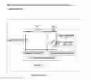
BRIEF DESCRIPTION OF THE SEVERAL VIEWS OF THE DRAWINGFIG. 1. General Equivalent Circuit for Power Sources.
FIG. 2. Simplified Equivalent Circuit with Equations.
FIG. 3. D.C. Model.
FIG. 4. Current Response Curve.
FIG. 5. Equations.
FIG. 6. 60 Hz Sine wave with pulse load Current.
DETAILED DESCRIPTION OF THE INVENTIONAC. Circuit Model
According to the venin's theorem of circuit equivalency an AC Power Source may be modeled by an infinite source Vs in series with an impedance which characterizes the effect a current load has on the power source (Ref. 6). This is illustrated in FIG. 1. Also in FIG. 1 is shown the schematic orientation of a normal load along with that of a short circuit.
Without a short circuit the current Is is limited by the series combination of the source impedance Zs and the load impedance ZL (Equation 1). However since the impedance of a short circuit approaches zero, short circuit current is limited only by the source impedance (Equation 2).
For power distribution networks the net equivalent reactance is correctly assumed to be inductive reactance. Furthermore the ratio of reactance to resistance is usually high enough such that resistance can be ignored or assigned an estimated value and still retains sufficient accuracy for AC short circuit calculations. The effects of these assumptions on FIG. 1 are shown in FIG. 2.
For a 60 Hz system, AC inductive reactance magnitude in ohms is computed by the formula
X=2 (multiplied by) pi (multiplied by) 60 (multiplied by) L
Where L in FIG. 2 is the Equivalent Inductance of the power source.
Thus it is seen that for electrical power distribution networks, that the magnitude of the available short circuit current at any point is largely determined by the source Equivalent Inductance.
DC Circuit Model
FIG. 3 illustrates the same circuit from a DC perspective (Ref. 7). The DC source voltage is considered to be the peak voltage of the previous AC sine wave. This is the previous RMS value multiplied by the square root of 2. Also illustrated is a switch and test load to help describe the method of inductance evaluation in question.
With the switch open, the current is zero. Upon switch closure the current rises as illustrated in FIG. 4. The formula for the current in this circuit is shown as Equation 3 (Ref. 8). The time required for the current to stabilize is considered to be 5 times R divided by L. The final value of I is seen to be Vs (divided by) R.
However, if the switch opens at the end of a load pulse interval (tp), the current will have risen to a value given as i(tp), If these values are inserted in Equation 3 and solved for L (Equations 3a through 4, FIG. 5) it is seen that the value for Equivalent Inductance may be calculated by this method. Several points of clarification must be made as follows:
-
- The effect of source resistance is neglected as it is very small compared to the test Resistance.
- The switch in the schematic in an actual implementation is a transistor or similar device.
- The method is valid as a one point sample but may also use a multipoint average.
- The inventors' contention is that, with the pulse duration adequately shorter than the AC Cycle, that the DC equations and analysis result in valuable results.
- Any and all simplifications and or omissions in this explanation do not materially affect The validity of the results.
Load Pulse.
As stated earlier, the timing and duration of the load pulse (illustrated by switch on and off cycle in FIG. 3) is a key to this method. It should start near the top of the AC sine wave of the system under test. This is because the voltage changes at a slower rate in this area thus making a DC evaluation easier and more accurate. If the method is implemented by taking multiple samples (the inventor's choice) then the pulse should start at close to the same voltage magnitude every time for overall accuracy.
The duration of the load pulse must be short relative to the rate of change of the AC sine wave voltage during the pulse interval. There is no defined ratio for this relationship. However, to the extent this relationship is true, the more accurate the method will be.
Implementation
The inventors implementation of this method is complex involving substantial circuitry and programming, none of which bears on the method as described. Any engineer or designer with experience with microprocessor based development can take the method as herein described and develop a valuable and important innovation. However, as a point of reference the inventors implementation includes the following; The microcontroller PIC18C4610 by Microchip Corporation is the heart of the device. The microcontrollers' A to D and comparator sub-systems are programmed and adapted to sense the top of the sine wave. A common operational amplifier circuit is used in a “peak hold” configuration to capture the voltage (and thus the current) transient across the load resistor. The microcontroller has binary I/O one of which functions as a driver for an insulated gate bipolar transistor (International Rectifier IRG4PF50WD) which functions as a high speed switch. The program is developed in “C” computer language with a compiler which includes a function for “natural logarithm” used in the method. The microcontroller is also connected to a numeric display and a keypad for user interface.
REFERENCES
- 1. Electrical Construction and Maintenance magazine, January 2005 “Perceptive Breaker Equals Improved Arc-Flash Protection” By Ellen Parson, Contributing Writer, first paragraph
- 2. National Fire Protection Association news release dated Sep. 13, 2004 entitled “NFPA & IEEE to Research Arc-Flash Phenomena” www.nfpa.org
- 3. www.arcadvisor.com/example.html#scmvafactor topic Fault Current Analysis, paragraphs 3 and 4
- 4. Cooper Bussman Fuses www.bussman.com publication entitled “Selecting Protective Devices” page 1 paragraph entitled “Short Circuits”
- 5. www.arcadvisor.com FAQ “What Is the MVA method for short circuit analysis?”
- 6. Basic Engineering Circuit Analysis 8th Edition by J. David Erwin and R. Mark Nelms; John Wiley & Sons Publishing, 2005, page 175
- 7. Basic Engineering Circuit Analysis 8th Edition by J. David Erwin and R. Mark Nelms; John Wiley & Sons Publishing, 2005, page 272
- 8. Basic Engineering Circuit Analysis 8th Edition by J. David Erwin and R. Mark Nelms; John Wiley & Sons Publishing, 2005, page 273
Claims
1. The inventor claims the application of a synchronized pulse load to an energized AC electrical component as a means to determine Equivalent Inductance of the sourcing system at that point.
2. The inventor claims the measurement and evaluation of (above referenced) test load current as a means to determine Equivalent Inductance of the sourcing system at the point of measure.
Images & Drawings included:


Sources:
- United States Patent and Trademark Office - verify current appl. status at the USPTO↗
Recent applications in this class:
- » 20240004414 2024-01-04
Power factor adjustment method and apparatus in waveguide circuit or transmission line circuit, and power generating transmission line system using the same - » 20210109558 2021-04-15
Bidirectional capacitor bank control - » 20210018948 2021-01-21
Power factor correction with active damping - » 20200379496 2020-12-03
Power factor correction circuit, control method and controller - » 20200379495 2020-12-03
Power factor correction circuit, control method and controller - » 20200356128 2020-11-12
Load shedding system for both active and reactive power based on system perturbation - » 20200183437 2020-06-11
Dynamic Power Factor Correction On Cross-Referenced Network Identified Devices - » 20200142437 2020-05-07
Power-source power factor control system, phase modifying apparatus, and active filter apparatus - » 20190187736 2019-06-20
State change detection apparatus, method, and non-transitory medium - » 20180181154 2018-06-28
FUEL CELL POWER PLANT WITH REAL AND REACTIVE POWER MODES