Paper feeding device
US20070104528A1
2007-05-10
11/557,075
2006-11-06
Abstract:
The invention provides a paper feeding device. The paper feeding device comprises a paper container and a paper-transmitting mechanism. The paper container comprises a first connecting portion. The paper-transmitting mechanism comprises a second connecting portion. The second connecting portion movably connected with the first connecting portion which makes the paper-transmitting mechanism keeping a constant angle to the carrying surface during a paper-feeding process.
Assignee:
- BENQ CORPORATION 317 🇹🇼 TAOYUAN, Taiwan
Interested in similar patents?
Get notified when new applications in this technology area are published.
Classification:
B41J13/103 » CPC main
Devices or arrangements specially adapted for supporting or handling copy material in short lengths, e.g. sheets; Sheet holders, retainers, movable guides , or stationary guides for the sheet feeding section
B65H3/0661 » CPC further
Separating articles from piles using friction forces between articles and separator; Rollers or like rotary separators for separating inclined-stacked articles with separator rollers above the stack
B65H2402/32 » CPC further
Constructional details of the handling apparatus; Supports; Subassemblies; Mountings thereof Sliding support means
B41J13/10 IPC
Devices or arrangements specially adapted for supporting or handling copy material in short lengths, e.g. sheets Sheet holders, retainers, movable guides , or stationary guides
Description
BACKGROUND OF THE INVENTION1. Field of the Invention
The present invention relates to a paper feeding device, and in particular relates to a paper feeding device in a copy machine or a printer etc.
2. Description of the Related Art
FIG. 1 shows that a conventional paper feeding device 10 comprises a paper container 11 and a paper-transmitting mechanism 12. The paper-transmitting mechanism 12 comprises an axle 121 and a roller 122. The paper-transmitting mechanism 12 pivots on the axle 121. The roller 122 rotates to transmit paper 20. Moreover, a line L between the axle 121 and the roller 122 and paper 20 form an included angle θ. Compare FIG. 1 with FIG. 2, the amount of paper 20 gradually decreases, thus, the paper-transmitting mechanism 12 pivots on the axle 121 and the included angle θ increases gradually, causing the position of the paper-transmitting mechanism 12 relative to the paper to change. Because the direction of a force exerted to each piece of paper by the paper-transmitting mechanism changes due to the variation in the position of the roller, the magnitude of the force changes too, paper jams and multi-feeding may occur in the paper feeding device 10 when a printer or a copy machine works.
BRIEF SUMMARY OF INVENTIONA detailed description is given in the following embodiments with reference to the accompanying drawings. The invention provides a paper feeding device. The paper feeding device comprises a paper container and a paper-transmitting mechanism. The paper container comprises a first connecting portion. The paper-transmitting mechanism comprises a second connecting portion. The first connecting portion and the second connecting portion can connected to keep the paper transmitting mechanism moving along a direction, whether increasing or decreasing the mount of paper in the paper container, a fixed angle between the paper-transmitting mechanism and paper in the paper container always exists and the force exerted to each piece of the papers in the paper container is constant.
BRIEF DESCRIPTION OF DRAWINGSThe present invention can be more fully understood by reading the subsequent detailed description and examples with references made to the accompanying drawings, wherein:
FIG. 1 is a schematic view of a conventional paper feeding device at full capacity;
FIG. 2 is a schematic view of a conventional paper feeding device having less paper than FIG. 1;
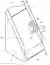
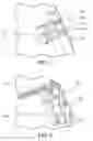
FIG. 3 is a schematic view of a paper feeding device of one embodiment of the invention;
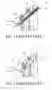
FIG. 4A is a sectional cross view along 4-4 of FIG. 3;
FIG. 4B is a schematic view of a paper feeding device having less paper than FIG. 4A;
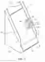
FIG. 5 is another embodiment of the invention; and
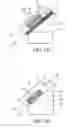
FIG. 6 is another embodiment of the invention.
DETAILED DESCRIPTION OF INVENTIONThe following description is of the best-contemplated mode of carrying out the invention. This description is made for the purpose of illustrating the general principles of the invention and should not be taken in a limiting sense. The scope of the invention is best determined by reference to the appended claims..
Referring to FIG. 3, the paper feeding device 30 comprises a paper container 31 and a paper-transmitting mechanism 32. The paper container 31 comprises two sides 311 and 312 and a carrying surface 313. The paper-transmitting mechanism 32 is installed on the side 312 to transmit paper 40 out of the paper container 31 along an arrow A.
Referring to FIGS. 3 and 4A, FIG. 4A is a sectional cross section along 4-4 of FIG. 3. The paper container 31 comprises a first connecting portion 314 disposed on the side 312. In this embodiment, the first connecting portion 314 is a groove. The paper-transmitting mechanism 32 comprises a second connecting portion 321 movably connected to the first connecting portion 314. In this embodiment, the second connecting portion 321 is a protrusion, such as a T type protrusion. Moreover, the paper-transmitting mechanism 32 further comprises two rollers 322 and 323 and a driving device 324. In this embodiment, the driving device 324 is a motor for driving the rollers 322 and 323 to transmit paper 40. The paper-transmitting mechanism 32 and the carrying surface 313 form a fixed angle. In this embodiment, the fixed angle is 0 degree or 180 degree. Because paper 40 is placed flat on the carrying surface 313, the carrying surface 313 is parallel to the paper. The paper-transmitting mechanism 32 is parallel to the carrying surface 313 and paper 40 thereon. The amount of paper 40 on the carrying surface 313 decreases because paper 40 is transmitted out of the paper container 31, thereby, the paper-transmitting mechanism 32 descends along an arrow C.
FIG. 4B shows the paper-transmitting mechanism 32 gradually descending. As amount of decreases paper, the paper-transmitting mechanism 32 stays parallel to the paper 40 on the carrying surface 313. The paper-transmitting mechanism 32 and the paper 40 on the carrying surface 313 form a fixed angle, thus, the amount of force exerted on each piece of paper 40 by the paper-transmitting mechanism 32 is the same, thus, paper jams and muilt-feeding is prevented.
FIG. 5 shows another embodiment of a paper feeding device comprising the paper-transmitting mechanism 32a on the side 312a of the paper container 31. The paper container 31 comprises two first connecting portions 314a and 314a′. The paper-transmitting mechanism 32a comprises a roller 322 and two second connecting portions 321a and 321a′. The second connecting portions 321a and 321a′ are respectively and movably connected to the first connecting portions 314a and 314a′. This embodiment is approximately similar to the embodiment of FIG. 3, thus, description of identical elements is omitted.
FIG. 6 shows another embodiment of a paper feeding device, wherein the paper-transmitting mechanism 32b comprises two rollers 322 and 323, a transmitting mechanism 325, an axle and a driving device (not shown). The driving device drives the axle 326, and drives the transmitting mechanism 325, and then drives the rollers 322 and 323. The transmitting mechanism 325 may be a pulley or a gear drive. This embodiment is approximately similar to the embodiment of FIG. 3, thus, description of identical elements is omitted.
While the invention has been described by way of example and in terms of the preferred embodiments, it is to be understood that the invention is not limited to the disclosed embodiments. To the contrary, it is intended to cover various modifications and similar arrangements (as would be apparent to those skilled in the art). Therefore, the scope of the appended claims should be accorded the broadest interpretation so as to encompass all such modifications and similar arrangements.
Claims
What is claimed is:1. A paper feeding device, comprising:
a paper container comprising:
a carrying surface for carrying the paper; and
at least a first connecting portion; and
a paper-transmitting mechanism comprising:
at least a second connecting portion;
wherein the second connecting portion of the paper-transmitting mechanism is movably connected to the first connecting portion of the paper container; and
the paper-transmitting mechanism is always kept at a constant angle to the carrying surface during a paper-feeding process.
2. The paper feeding device as claimed in claim 1, wherein the paper-transmitting mechanism further comprises a roller and a driving device, the driving device drives the roller to roll for transmitting the paper.
3. The paper feeding device as claimed in claim 1, wherein the first connecting portion comprises a groove and the second connecting portion comprises a protrusion movably installed in the groove.
4. The paper feeding device as claimed in claim 2, wherein the driving device comprises a motor.
5. The paper feeding device as claimed in claim 2, wherein the paper-transmitting mechanism further comprises a transmitting mechanism, the driving device drives the roller via the transmitting mechanism for transmitting the paper.
6. The paper feeding device as claimed in claim 1, wherein the paper-transmitting mechanism is parallel to the carrying surface.
7. A printer device, comprising: the paper feeding device of claim 1.
8. A copy machine device, comprising: the paper feeding device of claim 1.
Images & Drawings included:
Sources:
- United States Patent and Trademark Office - verify current appl. status at the USPTO↗
Similar patent applications:
- » 20060033259
Paper storage device, paper feeding device, and printing device comprising paper feeding device - » 20250153963
PAPER FEEDING DEVICE, PAPER FEEDING METHOD, RECORDING MEDIUM, AND IMAGE FORMING APPARATUS - » 20150239692
Paper feeding device and image forming device including paper feeding device - » 20120235929
Paper feeding device, image scanning device, paper feeding method and computer readable medium - » 20220402713
Paper feed device and image forming apparatus including paper feed device - » 20160121633
Paper feeding device, image forming apparatus, and method for controlling paper feeding device - » 20170341889
Paper feed device, image forming apparatus and method of controlling paper feed device - » 20220388795
PAPER FEED DEVICE, IMAGE FORMATION SYSTEM, AND CONTROL PROGRAM FOR PAPER FEED DEVICE - » 20160176666
PAPER FEEDING DEVICE AND PAPER FEEDING METHOD - » 20090045566
Paper feed device, and paper feed cassette, manual paper feed tray, and image forming apparatus including same
Recent applications in this class:
- » 20250033387 2025-01-30
TRAY AND IMAGE RECORDING APPARATUS - » 20250033386 2025-01-30
RECORDING DEVICE - » 20240416666 2024-12-19
SHEET ACCOMMODATING DEVICE AND RECORDING APPARATUS - » 20240336076 2024-10-10
MOVABLE ARMS FOR PRINTER INPUT TRAYS - » 20240217248 2024-07-04
LINKAGE MECHANISM FOR OPENING AND CLOSING AN INPUTTING TRAY AND AN OUTPUTTING TRAY TOGETHER - » 20230294428 2023-09-21
PRINTING APPARATUS AND ROLL HOLDING DEVICE - » 20230226832 2023-07-20
Recording device - » 20230143837 2023-05-11
Processing device and recording device including a medium receiving unit that receives a discharged medium - » 20220281246 2022-09-08
Foldable baffle structure - » 20220281245 2022-09-08
Feeder tray adjustable leveling assembly for specialty media
Recent applications for this Assignee:
- » 20090231371 2009-09-17
APPARATUS AND METHOD FOR SUPPLYING VOLTAGE TO NOZZLE IN INKJET PRINTER - » 20080310295 2008-12-18
METHODS FOR EXTRA APPENDING DATA IN A MULTIPLE LAYER DISC - » 20080239254 2008-10-02
Projector with enhanced grounding effect - » 20080150961 2008-06-26
DISPLAYS WITH EMBEDDED COLOR TRACKING ALGORITHM BASED ON PANEL OPTICAL CHARACTERISTICS - » 20080142664 2008-06-19
SUPPORTS FOR ELECTRONIC DEVICES - » 20080132258 2008-06-05
METHOD AND APPARATUS FOR BARRING SHORT MESSAGES - » 20080113546 2008-05-15
Portable electronic device - » 20080106529 2008-05-08
PROCESSING METHODS AND SYSTEMS FOR DRIVERS - » 20080104598 2008-05-01
SYSTEMS AND METHODS FOR OPERATION SCHEDULING - » 20080098381 2008-04-24
SYSTEMS AND METHODS FOR FIRMWARE UPDATE IN A DATA PROCESSING DEVICE