Methods and apparatus for discrete mirror processing
US20070105483A1
2007-05-10
11/266,984
2005-11-04
Abstract:
A method is described for the processing of substrates for utilization as discrete mirrors. The method includes temporarily mounting a first end of at least one substrate onto a grinding machine plate, engaging a second end of the at least one substrate with a grinding wheel, rotating the plate and grinding wheel in opposite directions, and moving the grinding wheel and the plate toward one another at a rate.
Inventors:
- Chad P. Stay 5 🇺🇸 Brooklyn Park, MN, United States
- David D. Nguyen 5 🇺🇸 Savage, MN, United States
Interested in similar patents?
Get notified when new applications in this technology area are published.
Classification:
B24B7/241 » CPC main
Machines or devices designed for grinding plane surfaces on work, including polishing plane glass surfaces; Accessories therefor characterised by a special design with respect to properties of the material of non-metallic articles to be ground for grinding inorganic material, e.g. stone, ceramics, porcelain for grinding or polishing glass Methods
B24B13/015 » CPC further
Machines or devices designed for grinding or polishing optical surfaces on lenses or surfaces of similar shape on other work; Accessories therefor of television picture tube viewing panels, headlight reflectors or the like
B24B49/00 IPC
Measuring; Indicating; Controlling
B24B49/00 IPC
Measuring or gauging equipment for controlling the feed movement of the grinding tool or work; Arrangements of indicating or measuring equipment, e.g. for indicating the start of the grinding operation
B24B1/00 IPC
Processes of grinding or polishing; Use of auxiliary equipment in connection with such processes
Description
BACKGROUND OF THE INVENTIONThis invention relates generally to ring laser gyroscopes, and more specifically, to methods and apparatus for processing of discrete mirrors utilized in ring laser gyroscopes.
Discrete mirror processing for at least one known ring laser gyroscope involves three processes normally used in optical fabrication, specifically, grinding, lapping, and polishing. The lapping and polishing processes typically utilize a loose abrasive slurry. The loose abrasive slurry comprises multiple abrasive particles dispersed in a liquid medium, for example, water. Although loose abrasive slurries are widely used in the lapping and polishing processes to provide an optically clear surface finish on glass articles, loose abrasive slurries also have many disadvantages associated therewith.
For example, such loose abrasive slurries must be periodically analyzed to assure quality and dispersion of the abrasive particles. The equipment associated with the loose abrasive slurry process must also be continually maintained. Maintenance of such equipment is costly due to the labor costs associated with the maintenance. Further, additional equipment is typically incorporated into the slurry process for the preparation, handling and disposal of the loose abrasive slurry mixtures. Also, the cost of maintaining a loose abrasive slurry process is costly in term of raw materials, equipment maintenance, disposal of used slurries and labor. Processes which use slurries are usually very untidy because the loose abrasive slurry splatters easily and is difficult to contain.
BRIEF SUMMARY OF THE INVENTIONIn one aspect, a method for processing glass substrates for utilization as discrete mirrors is provided. The method comprises temporarily mounting a first end of at least one substrate onto a grinding machine plate, engaging a second end of the at least one substrate with a grinding wheel, rotating the plate and grinding wheel in opposite directions, and moving the grinding wheel and the plate toward one another at a rate.
In another aspect, a process for fabricating a mirror from a substrate is provided. The method comprises rotating an end of the substrate in a first direction, configuring a grinding wheel with a matrix between nine and twenty-five microns, engaging the end of the substrate with the grinding wheel, and rotating the grinding wheel in a direction opposite that of the substrate.
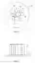
BRIEF DESCRIPTION OF THE DRAWINGSFIG. 1 is a top view illustration of a plurality of glass rods mounted to a grinding machine plate.
FIG. 2 is a side view of the plate and glass rods of FIG. 1.
FIG. 3 is a flowchart describing a glass rod grinding process.
DETAILED DESCRIPTION OF THE INVENTIONThe methods and apparatus described herein provides for the elimination of the loose abrasive slurry lapping process that is currently utilized in the fabrication of high precision optics. Specifically, a grinding process that enables high precision optics to be ground to the same or a better surface finish, with minimal sub-surface damage and clarity as compared to conventional loose abrasive lapping is described. This grinding process provides for the fabrication and modification of glass articles such that the loose abrasive lapping process is eliminated and the glass articles are moved directly to polishing processes.
FIGS. 1 and 2 illustrate a plurality of rods 10 mounted to a plate 12. In one embodiment, plate 12 is of the type that is utilized with a grinding machine. Utilizing the illustrated configuration provides for the fabrication of discrete mirrors and substrates using a multi-speed grinder (e.g., a grinding machine) enabling the elimination of loose abrasive slurry lapping. In an exemplary embodiment, plate 12 is attached to a NAG-250 multi-speed grinder on which is mounted a 9-25 micron metal, metal/resin or resin bond matrix, for example, a nine micron resin bond matrix diamond wheel. In the illustrated embodiment, plate 12 is a circular glass plate. Rods 10 include circular glass rods ranging from, for example, from 0.1 inches to about 3 inches, more specifically, from 0.305 inches to about 2.50 inches in diameter. Glass rods 10 are evenly spaced and temporarily mounted on glass plate 12. While described in terms of glass rods, it is to be understood that the processes described herein are not limited to such rods. Rather, substrates including, but not limited to, wafers, rods, cubes or other geometrical shapes may be polished as described herein.
In one embodiment, when attached to a grinding machine (not shown), glass plate 12 rotates clockwise at a speed of either about thirteen rpm (rough grind) or about four rpm (fine grind) while the grinding tool within the grinding machine rotates counter clockwise at a speed of either about 1000 rpm (rough grind) or about 1400 rpm (fine grind).
In addition to the rates of rotation, glass rods 10 (and plate 12) are moved towards the grinding wheel at a rate. For example, a rough grind feed rate is about 0.07 mm/min and a fine grind feed rate is about 0.015 mm/min. In these embodiments, a 0.5% coolant and water mixture is used to provide lubrication at the surfaces being ground and further helps to remove glass swarf between the surface of the grinding wheel and ends of glass rods attached to plate 12.
FIG. 3 is a flowchart 100 illustrating a rod grinding process utilizing the equipment and fixtures for grinding as described above. Specifically, glass rods 10 are mounted 102 onto a grinding machine plate 12. Rods 10 are mounted 102 at an end opposite the end that is to be ground and polished. The ends to be polished are then engaged 104 by a grinding wheel of the grinding machine.
The grinding machine plate 12 and grinding wheel are rotated 106 in opposite directions, and the grinding machine plate 12 and grinding wheel are moved 108 toward one another at a specific rate.
After the above described grinding process, the surface finish on the glass rods is evaluated with a diamond stylus. One example of such a diamond stylus is commercially available under the trade designation Mahr Pocket Surf available from Deterco, Inc., Houston, Tex. Initial surface finishes or Ra values of the of the ground ends of glass rods 10 typically fall within a range of 0.01 micrometer to 0.30 micrometer, while surface finishes utilizing a nine micron loose abrasive aluminum oxide slurry lapping process after an initial grinding range from 0.28 micrometer to 0.30 micrometer. Sub-surface damage of the ground ends of the glass rods typically fall within 2.87 micrometers to 3.05 micrometers while sub-surface damage of ground ends of glass rods polished using the above described lapping process is between 3.10 micrometers and 3.30 micrometers. The above described grinding process results in substrates and/or glass rods having a surface compatible with polishing processes that result in a polished substrate surface finish of between 1 Angstrom and 3 Angstroms.
While the invention has been described in terms of various specific embodiments, those skilled in the art will recognize that the invention can be practiced with modification within the spirit and scope of the claims.
Claims
1. A method for processing substrates for utilization as mirrors, said method comprising:
temporarily mounting a first end of at least one substrate onto a grinding machine plate;
engaging a second end of the at least one substrate with a grinding wheel;
rotating the plate and grinding wheel in opposite directions throughout processing to polish the substrates; and
moving the grinding wheel and the plate toward one another at a rate.
2. A method according to claim 1 further comprising providing a liquid lubricant between the second end of the at least one substrate and the grinding wheel.
3. A method according to claim 2 wherein providing a liquid lubricant comprises using a 0.5% coolant and water mixture to remove glass swarf between the grinding wheel and the surface of the at least one substrate.
4. A method according to claim 1 wherein rotating the plate and grinding wheel comprises rotating the plate between about thirteen revolutions per minute and about four revolutions per minute.
5. A method according to claim 1 wherein rotating the plate and grinding wheel comprises rotating the grinding wheel between about 1000 revolutions per minute and about 1400 revolutions per minute.
6. A method according to claim 1 wherein moving the grinding wheel and the plate toward one another at a rate comprises setting a feed rate between about 0.07 millimeters per minute and about 0.015 millimeters per minute.
7. A method according to claim 1 further comprising attaching a matrix to the grinding wheel, wherein attaching the matrix comprises selecting at least one of a metal bond matrix and a resin bond matrix.
8. A method according to claim 7 wherein selecting at least one of a metal bond matrix and a resin bond matrix comprises selecting a matrix having a particle size between nine and twenty-five microns.
9. A method according to claim 1 wherein the at least one substrate includes one or more of a wafer, a rod, and a cube fabricated from glass.
10. A method according to claim 1 wherein moving the grinding wheel and the plate toward one another comprises moving the grinding wheel and plate to provide a surface finish for the substrate of between 0.01 micrometer and 0.30 micrometer and sub-surface damage between 2.87 micrometers and 3.05 micrometers.
11. A process for fabricating a mirror from a substrate comprising:
rotating an end of the substrate in a first direction;
configuring a grinding wheel with a matrix having a particle size between 9 and 25 microns;
engaging the end of the substrate with a grinding wheel; and
rotating the grinding wheel in a direction opposite that of the substrate throughout the fabrication of the mirror.
12. A process according to claim 11 wherein rotating an end of the substrate in a first direction comprises rotating the substrate between about thirteen revolutions per minute and about four revolutions per minute.
13. A process according to claim 11 wherein rotating the grinding wheel comprises rotating the grinding wheel between about 1000 revolutions per minute and about 1400 revolutions per minute.
14. A process according to claim 11 further comprising providing a liquid lubricant at the engagement of the substrate and the grinding wheel.
15. A method according to claim 14 wherein providing a liquid lubricant comprises using a 0.5% coolant and water mixture to remove glass swarf between the grinding wheel and the surface of the substrate.
16. A method according to claim 11 further comprising moving the grinding wheel and the plate toward one another at a feed rate between about 0.07 millimeters per minute and about 0.015 millimeters per minute.
17. A method according to claim 11 wherein the substrate includes one or more of a wafer, a glass rod, and a cube.
18. A method according to claim 11 further comprising polishing to a resultant surface finish of between 0.01 micrometer and 0.30 micrometer.
19. A method according to claim 11 further comprising polishing to a resultant sub-surface damage of between 2.87 micrometers and 3.05 micrometers.
20. A method according to claim 11 further comprising polishing the substrate surface to a finish between 1 Angstrom and 3 Angstroms.
Images & Drawings included:


Sources:
- United States Patent and Trademark Office - verify current appl. status at the USPTO↗
Recent applications in this class:
- » 20240416475 2024-12-19
GLASS DEVICE HOUSINGS - » 20240359284 2024-10-31
GLASS POLISHING APPARATUS AND GLASS POLISHING METHOD USING THE SAME - » 20230226659 2023-07-20
Glass device housings - » 20220161385 2022-05-26
Glass device housings - » 20220134504 2022-05-05
WAFER GRINDING METHOD - » 20220088741 2022-03-24
Glass polishing apparatus and glass polishing method using the same - » 20210283739 2021-09-16
Glass object and method for forming a depression in a glass object for containing cremated ashes - » 20210162558 2021-06-03
POLISHING AGENT FOR SYNTHETIC QUARTZ GLASS SUBSTRATE, METHOD FOR MANUFACTURING THE POLISHING AGENT, AND METHOD FOR POLISHING SYNTHETIC QUARTZ GLASS SUBSTRATE - » 20210008681 2021-01-14
Cleaning method for optical surface monitoring device - » 20150375354 2015-12-31
Method for decoating a glass panel