Equalizing signal-to-interference ratios of different physical channels supporting a coded composite transport channel
US20070105593A1
2007-05-10
11/646,822
2006-12-28
Abstract:
A system and method for equalizing the signal-to-interference ratios (SIRs) of a plurality of physical channels supporting a coded composite transport channel CCTrCH comprises calculating new transmission powers such that not only are the SIRs of the physical channels equalized, but also the average SIR of the CCTrCH remains constant.
Assignee:
- INTERDIGITAL TECHNOLOGY CORPORATION 1,942 🇺🇸 Wilmington, DE, United States
Interested in similar patents?
Get notified when new applications in this technology area are published.
Classification:
H04W52/247 » CPC main
Power management, e.g. TPC [Transmission Power Control], power saving or power classes; TPC; TPC being performed according to specific parameters using SIR [Signal to Interference Ratio] or other wireless path parameters where the output power of a terminal is based on a path parameter sent by another terminal
H04W52/24 » CPC further
Power management, e.g. TPC [Transmission Power Control], power saving or power classes; TPC; TPC being performed according to specific parameters using SIR [Signal to Interference Ratio] or other wireless path parameters
H04L1/1812 » CPC further
Arrangements for detecting or preventing errors in the information received by using return channel in which the return channel carries supervisory signals, e.g. repetition request signals; Automatic repetition systems, e.g. van Duuren system ; ARQ protocols Hybrid protocols
H04B1/38 IPC
Details of transmission systems, not covered by a single one of groups - ; Details of transmission systems not characterised by the medium used for transmission Transceivers, i.e. devices in which transmitter and receiver form a structural unit and in which at least one part is used for functions of transmitting and receiving
H04M1/00 IPC
Substation equipment, e.g. for use by subscribers
Description
CROSS REFERENCE TO RELATED APPLICATION(S)This application is a continuation of U.S. patent application Ser. No. 10/629,420 filed Jul. 29, 2003, which claims the benefit of U.S. Provisional Application Serial No. 60/399,811 filed on Jul. 31, 2002, which is incorporated by reference as if fully set forth.
FIELD OF THE INVENTIONThe present invention relates to wireless, time slotted communication systems. More specifically, the present invention is directed to a method of equalizing the signal-to-interference ratios of different physical channels supporting a coded composite transport channel without modifying the average signal to interference ratios of a coded composite transport channel.
BACKGROUNDThere are many types of shared wireless communications networks, such as those used in Third Generation (3G) cellular telephony communications. One of the techniques used in wireless communications equipment using a shared network includes the allocation of transmit power for communications in different channels. By effectively controlling the transmit power, it is possible to reduce overall power consumption, increase utilization of bandwidth and maintain at the appropriate value the signal-to-interference ratios (SIRs) of the different physical channels supporting a coded composite transport channel (CCTrCH).
In certain current wireless systems, the different types of data a user needs to transmit or receive may be coded and multiplexed in one or more CCTrCHs.
The multiplexing is performed in a way that the quality of service (QoS) for those different types of data, in terms of the probability of receiving a transport block in error, will be met for the same value of the SIR of the received symbols of the CCTrCH. This allows an optimal use of the radio resources. These systems are able to transmit a wide range of services, from high data rate services such as video and Internet downloads, to low data rate services such as voice.
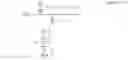
Referring to FIG. 1, a plurality and variety of user services are graphically shown as individual data streams. These individual data streams are assigned to transport channels A, B and C, whereby the data streams are coded and multiplexed. Each transport channel A, B, C is assigned a specific coding rate and a specific transmission time interval (TTI). The coding rate for each transport channel determines the number of transmitted bits of the physical layer, and the TTI defines the delivery period of the block of data to be transmitted. For example, the TTI may be 10, 20, 40 or 80 ms. Coded bits from the various transport channels are multiplexed and interleaved to form a CCTrCH. The bits of a CCTrCH are then paired to form symbols, which are transmitted (after spreading) through one or a plurality of physical channels defined in terms of time slot and spreading code.
The transmission on physical channels occurs after the transport channels have been multiplexed onto the CCTrCH. The number of symbols (Ns) carried by a physical channel is inversely proportional to the spreading factor of the code of the physical channel. In other words, Ns=Nc/G, where Nc is the number of chips spreading the symbols in a time slot, and G is the spreading factor. The number of chips Nc is normally the same for all physical channels supporting a CCTrCH.
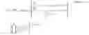
Referring to FIG. 2, at the transmitter side each physical channel is transmitted at a certain power level Pi, where the index i is over the physical channels. At the receiver side, the signal from a physical channel has a power level Ri=Pi/L where L is the path loss. After despreading, the power of the received symbols is Gi*Pi/L, where Gi is the spreading factor of the physical channel. Therefore, if the interference level is Ii in the slot occupied by the physical channel, the SIR in this physical channel, at the symbol level, is given by Equation (1): SIR i = G i P i LI i Equation ( 1 )
The quality of reception of a CCTrCH, in terms of the probability of receiving a transport block in error, is a function of the SIRs of the received symbols. When the SIRs of the received symbols all have the same value, this value is a direct indicator of the quality of the connection. In general, however, the SIRs of received symbols may have different values. An approximate indicator of the quality of the connection may be obtained by averaging the values of the SIRs of the received symbols. In essence, the quality of the connection with unequal SIRs of symbols, whose average value is SIR, should be approximately the same as the quality of a connection with the SIRs of symbols all equal to SIR.
The averaging can be done linearly or logarithmically (i.e., averaging the SIR values in dB). The logarithmic average is always lower than the linear average, and as such, can be considered a more conservative indicator of the quality of the connection. The computations can be used to provide linear or logarithmic averages, as a function of the different power levels of the physical channels of the CCTrCH.
To perform a linear average, the average SIR of the CCTrCH ( SIRlin) is computed as follows:
SIR
_
lin
=
∑
i
=
1
N
(
Number
of
symbols
in
physical
channel
i
)
×
SIR
i
Total
number
of
symbols
in
all
physical
channels
Equation
(
2
)
The SIR of each physical channel is multiplexed by the number of symbols it is carrying to compute the average over all symbols of the CCTrCH. Since the number of symbols in physical channel i is equal to Nc/Gi, and substituting Equation (1) for SIRi, this becomes:
SIR
_
lin
=
∑
i
=
1
N
(
N
c
/
G
i
)
×
(
G
i
P
i
/
L
I
i
)
∑
i
=
1
N
(
N
c
/
G
i
)
=
∑
i
=
1
N
P
i
I
i
L
∑
i
=
1
N
1
G
i
Equation
(
3
)
Equation (3) expresses the linear average SIR ( SIRlin)of the CCTrCH as a function of the transmission power levels (Pi), interference levels (Ii) and spreading factors (Gi) of all physical channels, as well as the path loss (L).
The logarithmic average SIR ( SIRlog) of the CCTrCH is defined, following similar principles, as follows: log 10 ( SIR _ log ) = ∑ i = 1 N ( Number of symbols in physical channel i ) × log 10 ( SIR i ) Total number of symbols in all physical channels = ∑ i = 1 N ( N c / G i ) × log 10 ( G i P i / L I i ) ∑ i = 1 N ( N c / G i ) = ∑ i = 1 N ( 1 / G i ) × log 10 ( G i P i / L I i ) ∑ i = 1 N ( 1 / G i ) Equation ( 4 )
Equation (4) expresses the logarithmic average SIR of the CCTrCH as a function of the transmission power levels (Pi), interference levels (Ii) and spreading factors (Gi) of all physical channels, as well as the path loss (L).
In most current wireless systems the downlink power control is closed-loop. This means that the base station must adjust the transmit power every frame based on up/down transmit power control (TPC) commands sent by the mobile unit during an uplink transmission, (for example, uplink CCTrCH). The mobile unit determines the TPC command by comparing the experienced SIR to a certain SIR target. While the downlink CCTrCH of a mobile unit may have physical channels occupying more than one slot, multiple TPC commands per frame would be possible only in case of multiple uplink CCTrCHs. In many cases however, there is only a single uplink CCTrCH for a mobile unit. In this situation, there is only one TPC command per frame that the mobile unit can send to command the power transmitted by the base station on more than one slot.
Since the interference signal code power (ISCP) on each downlink slot is subject to variations over time, the downlink CCTrCH may be adversely affected. For example, assuming physical channels on 2 slots, over a certain period of time the ISCP on the first slot may increase by 5 dB while the ISCP on the second slot may decrease by 3 dB. Using a single TPC command to control the transmission power on those two slots, it is impossible for the mobile unit to inform the base station to increase the power on one slot but decrease the power on the other slot. As a result, the SIRs of the downlink physical channels occupying different slots are very likely to drift apart if the base station strictly follows the TPC commands sent by the mobile unit, because the base station has to apply the same TPC command to all physical channels regardless of the slots they are occupying.
It is desirable for an optimal use of the radio resources that the SIRs of the different physical channels be as equal as possible at the symbol level. To achieve this, and because interference conditions in the different time slots change over time, the system needs to readjust, from time to time, the transmission powers allocated in each timeslot to the different physical channels so that the SIRs of the physical channels which are in different slots become as equal as possible. This process is known as SIR equalization and is achieved through the process shown in FIG. 3.
FIG. 3 shows the process implemented by a Controlling Radio Network Controller (CRNC), a base station and a mobile unit to perform SIR equalization. This process enables the base station to use the downlink timeslot ISCP values when deciding the downlink TX power for each timeslot. The mobile unit periodically measures downlink (DL) ISCP and transmits ISCP measurements to the CRNC for each timeslot in which it is receiving a signal. The CRNC sends a DL POWER TIMESLOT CONTROL REQUEST message to the base station, along with DL ISCP values, which are the interference levels in every slot occupied by the physical channels for the concerned CCTrCH. Upon reception, the base station uses the indicated DL timeslot ISCP values sent by the CRNC to set the downlink TX power for each timeslot. The base station reduces the downlink TX power in those downlink timeslots of the radio link where the interference is low; and increases the downlink TX power in those timeslots where the interference is high, while keeping the total downlink power in the radio link unchanged.
The procedure 30 followed by the base station for performing SIR equalization is detailed in FIG. 4. The procedure 30 starts with the reception of the DOWNLINK POWER TIMESLOT CONTROL REQUEST message from the CRNC containing the ISCP values (step 32). The base station associates interference levels Ii to the different physical channels, where the index i is over the physical channels, depending on the time slot occupied by each of the physical channels (step 34). The interference level I is the same for all physical channels that occupy the same time slot, (i.e., Ii=Ij if physical channels i and j are in the same time slot.) Since the base station is responsible for the transmission of the signal to the mobile unit, it always knows the latest transmitted power level Pi as well as the spreading factor Gi of every physical channel.
The base station then takes these set of values (I1, I2, . . . , IN, P1, P2, . . . , PN, G1, G2, . . . , GN), where N is the number of physical channels supporting the CCTrCH, and computes a new set of values (P1′, P2′, . . . , PN′) for the transmission power levels of the physical channels (step 36). The goal of equalization is to make the SIR of all physical channels equal. Accordingly;
SIR
i
′
=
G
i
P
i
′
L
I
i
=
K
Equation
(
5
)
In Equation (5), SIR′i denotes the SIR of physical channel i just after equalization, and K is the value of the SIR after equalization, which must be the same for all physical channels. In one prior art system, this value K is computed according to the following:
K
=
∑
i
=
1
N
P
i
L
∑
i
=
1
N
I
i
G
i
Equation
(
6
)
Substituting Equation (6) in Equation (5), the new set of transmission power values (P1′, P2′, . . . , PN′) is therefore computed by applying the following equation:
P
i
′
=
(
∑
i
=
1
N
P
i
∑
i
=
1
N
I
i
G
i
)
I
i
G
i
Equation
(
7
)
Immediately after application of Equation (7), the SIRs of the physical channels are all equal. In addition, it can be verified that the sum of the transmission powers is the same before and after SIR equalization
(
∑
i
=
1
N
P
i
′
=
∑
i
=
1
N
P
i
)
.
These new power values (Pi′, P2′, . . . PN′) are then applied to the physical channels (step 38).
While the process shown in FIG. 4 and set forth in Equation 7 equalizes the SIRs of the different physical channels, it suffers from a major drawback. Although, the total power over all physical channels before and after SIR equalization is the same, the SIR of the physical channels after application of the new set of transmission powers Pi′ could be significantly different from the average SIR over all physical channels before equalization, as defined according to either Equation (3) (linear average) or Equation (4) (logarithmic average). As a result, the quality of the reception may suffer a sudden and severe degradation until power control eventually restores the average SIR to its original level.
Therefore, there are instances in which the existing equalization process does not maintain the average SIR constant. By the way of example, the CCTrCH may be supported by two physical channels of equal spreading factors, (such as G1=G2=16). The transmission power levels of the physical channels before equalization are P1=P2=1 mW. The corresponding interference levels are: I1=1×10⁻⁹ mW and I2=8 ×10⁻⁹ mW. The path loss is L=1×10⁹. Prior to SIR equalization, the SIRs of physical channels are therefore: SIR1=16 and SIR2=2. The average SIR (linear) is SIRlin =9 according to Equation (3). The average SIR (logarithmic) is SIRlog=5.7. After SIR equalization, Equation (7) shows that the new transmission power levels are: P1′=0.22 mW and P2′=1.78 mW, and the SIRs of both physical channels (as well as the average SIR, linear or logarithmic) is equal to SIRlin= SIRlog=SIR1=SIR2=3.56. Clearly, this is lower than both the linear or logarithmic average SIR before the SIR equalization procedure. If the average SIR, either linear or logarithmic, was at a level such that the QoS was just met for this CCTrCH, this reduction would result in a degradation of quality until power control restores the average SIR to its original level. This behavior is undesirable.
SUMMARY OF THE INVENTIONAccording to the present invention, SIRs of physical channels are equalized in a CCTrCH. New transmission power levels are calculated for multiple physical channels such that not only SIRs of physical channels are equalized, but also the average SIR of the CCTrCH remains constant. According to the present invention, the total transmission power of the CCTrCH does not necessarily remain constant, as in prior art arrangements.
In one embodiment of the invention, the linearly averaged SIR remains constant after SIR equalization. In another embodiment, the logarithmically averaged SIR remains constant.
BRIEF DESCRIPTION OF THE DRAWINGSFIG. 1 is a block diagram of prior art individual data streams being combined into a CCTrCH transmitted over a plurality of physical channels.
FIG. 2 is a diagram of prior art physical channels being transmitted over the air interface.
FIG. 3 is a flow diagram of a prior art signaling procedure between the CRNC, the base station and a mobile unit for SIR equalization.
FIG. 4 is a flow diagram of a prior art SIR equalization procedure, as performed at the base station.
FIG. 5 is a flow diagram of the SIR equalization procedure in accordance with the present invention.
FIG. 6 is a block diagram of a base station made in accordance with the present invention.
DETAILED DESCRIPTION OF THE PREFERRED EMBODIMENT(S)The present invention will be described with reference to the drawing figures where like numerals represent like elements throughout.
Referring to a procedure 40 in accordance with the present invention shown in FIG. 5, the base station receives the DL POWER TIMESLOT CONTROL REQUEST message from the CRNC, along with the interference levels in all time slots used by the physical channels supporting the CCTrCH subject to SIR equalization (step 41). The base station thus knows the interference levels (I1, I2, . . . , IN) associated to every physical channel supporting the CCTrCH, (where N is the number of physical channels). Additionally, the base station knows the latest transmission power levels (P1, P2, . . . , PN) of every physical channel along with their spreading factors (G1, G2, . . . , GN) (step 42). As understood by those of skill in the art, the entity that manages the transmission power levels, (i.e., the power control manager 70 shown in FIG. 6) is located in the base station. The spreading factors are also known by the base station, as it received this information from the CRNC upon setting up the connection.
The base station, using the interference levels (I1, I2, . . . , IN), the latest transmission powers (P1, P2, . . . , PN) and spreading factors (G1, G2, . . . , GN) of every physical channel, implements a function (f) representing the product between the average SIR and the path loss (step 43). The function (f) may be based on either linear averaging or logarithmic averaging of the symbol-weighted SIRs of the physical channels.
In the case where the linear definition of average SIR is used as in Equation (3), the function (f) is computed as follows: f = L SIR _ lin = ∑ i = 1 N P i I i ∑ i = 1 N 1 G i Equation ( 8 )
Essentially, for each physical channel, the ratio between the transmission power Pi of a physical channel and its interference level Ii is computed. Then the ratios for all physical channels are summed and this sum is divided by the sum of the inverse of spreading factors of all physical channels.
In the case where the logarithmic definition of average SIR is used as in Equation (4), the function (f) is expressed as follows:
f
=
L
SIR
_
log
=
L
exp
10
(
∑
i
=
1
N
(
1
/
G
i
)
×
log
10
(
G
i
P
i
/
L
I
i
)
∑
i
=
1
N
(
1
/
G
i
)
)
=
[
∏
i
=
1
N
(
G
i
P
i
I
i
)
1
G
i
]
1
/
∑
i
=
1
N
1
G
i
Equation
(
9
)
Note that in the special case where the spreading factors are all equal (G1=G2=. . . =GN=G), as in the Time Division Duplex (TDD) (3.84 Mcps) mode of UTRA, Equation (9) simplifies to:
f
=
G
(
∏
i
=
1
N
P
i
I
i
)
1
/
N
Equation
(
10
)
where G is the spreading factors of all physical channels.
Essentially, for each physical channel, the ratio between the transmission power Pi of a physical channel and its interference level Ii is computed. Then the Nth root (e.g. square root if N=2, cubic root if N=3, etc.), where N is the number of physical channels, of the product of the ratios for all physical channels is computed, and the result is multiplied by the spreading factor G. Alternatively, the Nth root of each ratio could be computed and then multiplied together. One skilled in the art should realize that any type of function that obtains the same results is included within the scope of the present invention.
After having computed the function (f), the base station computes the new transmission power levels (P′1, P′2, . . . , P′N) to assign to the physical channels (step 44), using the following: P i ′ = I i G i f Equation ( 11 )
Finally, the base station assigns the new transmission power levels (P′1, P′2, . . . , P′N) to the physical channels of the CCTrCH, (step 45).
As described hereinbefore, the present invention achieves the following two goals: 1) the symbol-level SIRs of all of the physical channel are equal to each other; and 2) the average SIR of the CCTrCH (linear or logarithmic) is the same as before SIR equalization.
It should be apparent that Equation (11) satisfies the two conditions since the symbol-level SIR of every physical channel after equalization are then all equal to: SIR i ′ = G i P i ′ I i 1 L = f L = SIR _ Equation ( 12 )
As those of skill in the art should realize, other definitions of the average SIR of a CCTrCH may be possible, aside from the two explicitly defined this description, (linear and logarithmic).
An alternative method for equalizing the SIRs of the physical channels, while maintaining the average SIR constant according to another definition, is the same as hereinbefore described, except that the function (f) is modified to correspond to the product between the path loss and the chosen definition of average SIR.
Applying the new transmission powers using the method in accordance with the present invention will not change the average SIR of the CCTrCH, which is beneficial to the quality of service for this CCTrCH. Additionally, the mobile unit does not need to do anything special when SIR equalization occurs; rather the mobile unit will experience equal SIR across all physical channels after SIR equalization takes place.
FIG. 6 is a base station 60 made in accordance with the present invention. The base station 60 receives from the CRNC 62 user data 64 (coming from the core network) and signaling messages 66, such as the DL POWER TIMESLOT CONTROL REQUEST message used for the SIR equalization process. The radio network interface 68 is responsible for decoding and interpreting the signaling messages from the CRNC 62. It thus controls the various parameters implemented in the physical layer processing unit 72 undertaken on the user data 64.
The power control manager 70 is responsible for providing the appropriate transmission power levels to the physical channels power unit 74 where the signals from each physical channel are weighted according to their respective power levels, before modulation in the modulator 76 and transmission of these physical channels via the antenna 78.
When SIR equalization takes place, the DL POWER TIMESLOT CONTROL REQUEST message is received by the radio network interface 68, which then forwards to the power control manager 70 the interference levels in very slot used by the concerned CCTrCH. The power control manager 70 then computes the new transmission power levels to apply to the physical channels of the concerned CCTrCH, as hereinbefore described with respect to the present invention. The physical layer processing unit 72 processes the user data 64, and forwards the physical channel to the physical channel power unit 74. The power levels are used by the physical channel power unit 74 to appropriately set the power of each physical channel. The channels are then modulated in the modulator 76 and transmitted via the antenna 78.
The present invention was described in conjunction with the application of the invention for use with voice as well as data according to a 3G system. However, the 3G system was used only as an example, and the invention can be applied to other wireless communication systems where data can be transmitted over multiple channels which may or may not be power-controlled by the same TPC commands and where the interference can be different.
While the present invention has been described in terms of the preferred embodiment, other variations which are within the scope of the invention as outlined in the claims below will be apparent to those skilled in the art.
Claims
What is claimed is:1. A base station (BS) configured for communicating on a plurality of physical channels (PCHs), the BS comprising:
a radio network interface for decoding and interpreting user data sent from a controlling radio network controller (C-RNC);
a physical layer processing unit for processing the user data;
a power control manager in communication with said radio network interface and receiving a measured interference level of each PCH from said radio network interface, said power control manager determining a new transmission power of each PCH using the measured interference levels; and
a physical channel power unit in communication with said physical layer processing unit and said power control manager, said physical layer processing unit forwarding a PCH to said physical channel power unit, said physical channel power unit setting the new transmission power of the PCH, wherein a signal to interference ratio of each PCH is equalized.
2. The BS according to claim 1, wherein said new transmission power is determined based on at least a most recent transmission power level of the PCH.
3. The BS according to claim 1, wherein said new transmission power is determined based on at least a spreading factor of the PCH.
4. The BS of claim 1 wherein the SIRs of the physical channels are equalized in a coded composite transport channel.
5. The BS of claim 1 wherein the SIRs of the physical channels are equalized so that the average SIR of a CCTrCH remains constant.
6. The BS of claim 5 wherein the average SIR is a linearly averaged SIR.
7. The BS of claim 5 wherein the average SIR is a logarithmically averaged SIR.
8. An integrated circuit for equalizing the signal to interference ratios (SIRs) of a plurality of physical channels (PCHs), each PCH having a first transmission power, said integrated circuit comprising:
a SIR determining device, for determining the SIR of each of said plurality of PCHs;
an averaging device, for determining a first average SIR based upon the SIRs for each of said plurality of PCHs; and
a transmission power determining device, for determining a new transmission power level for each of said plurality of PCHs, wherein the new transmission power levels ensure that the new SIRs of each of said plurality of PCHs are equal to each other and that the new average SIR for said plurality of PCHs is substantially the same as the first average SIR.
9. The integrated circuit according to claim 8, wherein the first average is a linear weighted average.
10. The integrated circuit according to claim 8, wherein the first average is a logarithmically weighted average.
11. The integrated circuit of claim 8 wherein said plurality of PCHs is a coded composite transport channel (CCTrCH).
Images & Drawings included:


Sources:
- United States Patent and Trademark Office - verify current appl. status at the USPTO↗
Recent applications in this class:
- » 20230247566 2023-08-03
Power control method and user equipment in device to device communication in serving cell - » 20220095241 2022-03-24
METHODS AND APPARATUS TO COMMUNICATE WITH AN END POINT DEVICE - » 20210314881 2021-10-07
Power control method and user equipment in device to device communication in serving cell - » 20210235393 2021-07-29
Methods and apparatus to communicate with an end point device - » 20200280931 2020-09-03
Power control method and user equipment in device to device communication in serving cell - » 20200100192 2020-03-26
ADAPTIVE TRANSMISSION POWER CONTROL FOR WIRELESS COMMUNICATION SYSTEMS - » 20190208476 2019-07-04
Power control method and apparatus and communication system - » 20190191388 2019-06-20
Power control method and user equipment in device to device communication in serving cell - » 20180310255 2018-10-25
Combining Signals In A Radio Unit - » 20180270766 2018-09-20
Power control method and user equipment in device to device communication in serving cell
Recent applications for this Assignee:
- » 20250024392 2025-01-16
METHOD AND APPARATUS FOR MAINTAINING UPLINK SYNCHRONIZATION AND REDUCING BATTERY POWER CONSUMPTION - » 20240388992 2024-11-21
DL BACKHAUL CONTROL CHANNEL DESIGN FOR RELAYS - » 20240362110 2024-10-31
ERROR DETECTION AND CHECKING IN WIRELESS COMMUNICATION SYSTEMS - » 20240276369 2024-08-15
DRX CYCLE LENGTH ADJUSTMENT CONTROL - » 20240251433 2024-07-25
Determining and sending channel quality indicators (CQIS) for different cells - » 20240155485 2024-05-09
Method and apparatus for enhancing discontinuous reception in wireless systems - » 20240107542 2024-03-28
Method and apparatus for providing and utilizing a non-contention based channel in a wireless communication system - » 20240098670 2024-03-21
Method and apparatus for maintaining uplink synchronization and reducing battery power consumption - » 20240048332 2024-02-08
LOGICAL CHANNEL MANAGEMENT IN A WIRELESS COMMUNICATION NETWORK - » 20240032085 2024-01-25
DYNAMIC RESOURCE ALLOCATION, SCHEDULING AND SIGNALING FOR VARIABLE DATA RATE SERVICE IN LTE