Flexible stent
US20070106369A1
2007-05-10
11/636,768
2006-12-11
✅ Patent granted
US 7,637,938 B2
2009-12-29
-
-
Kevin T Truong
2027-04-02
Abstract:
A flexible tubular stent including loosely interlocked annular elements without intersections or cross-over points.
Inventors:
- Brian J. BROWN 56 🇺🇸 Hanover, MN, United States
- Timothy J. LEY 23 🇺🇸 Shoreview, MN, United States
Assignee:
- BOSTON SCIENTIFIC SCIMED, INC. 8,398 🇺🇸 Maple Grove, MN, United States
Interested in similar patents?
Get notified when new applications in this technology area are published.
Classification:
A61F2/06 IPC
Filters implantable into blood vessels; Prostheses, i.e. artificial substitutes or replacements for parts of the body; Appliances for connecting them with the body; Devices providing patency to, or preventing collapsing of, tubular structures of the body, e.g. stents; Prostheses implantable into the body; Hollow or tubular parts of organs, e.g. bladders, tracheae, bronchi or bile ducts Blood vessels
A61F2/915 » CPC main
Filters implantable into blood vessels; Prostheses, i.e. artificial substitutes or replacements for parts of the body; Appliances for connecting them with the body; Devices providing patency to, or preventing collapsing of, tubular structures of the body, e.g. stents; Devices providing patency to, or preventing collapsing of, tubular structures of the body, e.g. stents; Stents in a form characterised by the wire-like elements; Stents in the form characterised by a net-like or mesh-like structure characterised by a net-like or mesh-like structure made from perforated sheet material or tubes, e.g. perforated by laser cuts or etched holes with bands having a meander structure, adjacent bands being connected to each other
A61F2/89 » CPC further
Filters implantable into blood vessels; Prostheses, i.e. artificial substitutes or replacements for parts of the body; Appliances for connecting them with the body; Devices providing patency to, or preventing collapsing of, tubular structures of the body, e.g. stents; Devices providing patency to, or preventing collapsing of, tubular structures of the body, e.g. stents; Stents in a form characterised by the wire-like elements; Stents in the form characterised by a net-like or mesh-like structure the wire-like elements comprising two or more adjacent rings flexibly connected by separate members
A61F2/90 » CPC further
Filters implantable into blood vessels; Prostheses, i.e. artificial substitutes or replacements for parts of the body; Appliances for connecting them with the body; Devices providing patency to, or preventing collapsing of, tubular structures of the body, e.g. stents; Devices providing patency to, or preventing collapsing of, tubular structures of the body, e.g. stents; Stents in a form characterised by the wire-like elements; Stents in the form characterised by a net-like or mesh-like structure characterised by a net-like or mesh-like structure
A61F2002/3011 » CPC further
Filters implantable into blood vessels; Prostheses, i.e. artificial substitutes or replacements for parts of the body; Appliances for connecting them with the body; Devices providing patency to, or preventing collapsing of, tubular structures of the body, e.g. stents; Prostheses implantable into the body; Joints; Additional features of subject-matter classified in , and subgroups thereof; Shapes Cross-sections or two-dimensional shapes
A61F2002/30324 » CPC further
Filters implantable into blood vessels; Prostheses, i.e. artificial substitutes or replacements for parts of the body; Appliances for connecting them with the body; Devices providing patency to, or preventing collapsing of, tubular structures of the body, e.g. stents; Prostheses implantable into the body; Joints; Additional features of subject-matter classified in , and subgroups thereof; The prosthesis having different structural features at different locations within the same prosthesis; Connections between prosthetic parts; Special structural features of bone or joint prostheses not otherwise provided for; The prosthesis having different structural features at different locations within the same prosthesis differing in thickness
A61F2002/30329 » CPC further
Filters implantable into blood vessels; Prostheses, i.e. artificial substitutes or replacements for parts of the body; Appliances for connecting them with the body; Devices providing patency to, or preventing collapsing of, tubular structures of the body, e.g. stents; Prostheses implantable into the body; Joints; Additional features of subject-matter classified in , and subgroups thereof; The prosthesis having different structural features at different locations within the same prosthesis; Connections between prosthetic parts; Special structural features of bone or joint prostheses not otherwise provided for Connections or couplings between prosthetic parts, e.g. between modular parts; Connecting elements
A61F2002/826 » CPC further
Filters implantable into blood vessels; Prostheses, i.e. artificial substitutes or replacements for parts of the body; Appliances for connecting them with the body; Devices providing patency to, or preventing collapsing of, tubular structures of the body, e.g. stents; Devices providing patency to, or preventing collapsing of, tubular structures of the body, e.g. stents more than one stent being applied sequentially
A61F2002/91533 » CPC further
Filters implantable into blood vessels; Prostheses, i.e. artificial substitutes or replacements for parts of the body; Appliances for connecting them with the body; Devices providing patency to, or preventing collapsing of, tubular structures of the body, e.g. stents; Devices providing patency to, or preventing collapsing of, tubular structures of the body, e.g. stents; Stents in a form characterised by the wire-like elements; Stents in the form characterised by a net-like or mesh-like structure characterised by a net-like or mesh-like structure made from perforated sheet material or tubes, e.g. perforated by laser cuts or etched holes with bands having a meander structure, adjacent bands being connected to each other characterised by the phase between adjacent bands
A61F2002/9155 » CPC further
Filters implantable into blood vessels; Prostheses, i.e. artificial substitutes or replacements for parts of the body; Appliances for connecting them with the body; Devices providing patency to, or preventing collapsing of, tubular structures of the body, e.g. stents; Devices providing patency to, or preventing collapsing of, tubular structures of the body, e.g. stents; Stents in a form characterised by the wire-like elements; Stents in the form characterised by a net-like or mesh-like structure characterised by a net-like or mesh-like structure made from perforated sheet material or tubes, e.g. perforated by laser cuts or etched holes with bands having a meander structure, adjacent bands being connected to each other Adjacent bands being connected to each other
A61F2220/0025 » CPC further
Fixations or connections for prostheses classified in groups - or or or or subgroups thereof Connections or couplings between prosthetic parts, e.g. between modular parts; Connecting elements
A61F2230/0002 » CPC further
Geometry of prostheses classified in groups - or or or or subgroups thereof Two-dimensional shapes, e.g. cross-sections
A61F2250/0036 » CPC further
Special features of prostheses classified in groups - or or or or subgroups thereof having different values of a given property or geometrical feature, e.g. mechanical property or material property, at different locations within the same prosthesis differing in thickness
Description
CROSS-REFERENCE TO RELATED APPLICATIONSThis application is a Continuation of U.S. application Ser. No. 10/160,531 filed May 31, 2002 which is a continuation of U.S. application Ser. No. 09/426,479 filed Oct. 26, 1999 (now U.S. Pat. No. 6,409,753), the contents of which are hereby incorporated by reference in their entirety.
BACKGROUND OF THE INVENTIONThis invention relates to stents which are implanted in the body.
Stents are used in body lumens, such as blood vessels to maintain them in an open condition. Typically, the stent is delivered into the lumen by a catheter that supports the stent in a compact form during percutaneous insertion and transport through a lumen, such as a vessel, to the desired implantation site. Upon reaching the site the stent is expanded so that it engages the interior wall of the vessel. The catheter is then removed, leaving the stent in the body.
The expansion of the stent may involve forcing it to expand radially outwardly as by inflation of a balloon carried by the catheter or the stent may be of a self-expanding type, several of which are known in the art. For example, the stent may be made of a memory metal such as NITINOL which self-expands in selected temperature ranges.
It can be readily seen that the more flexible the stent is during percutaneous insertion the more easily it can negotiate bends and curves in the lumen or vessel to reach the implantation site.
SUMMARY OF THE INVENTIONThis invention provides a stent design of individual annular elements shaped so as to loosely interfit or interlock together with or without intersection and without cross-over points whereby the stent exhibits unusual flexibility.
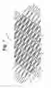
Preferably, the annular elements are multiple independent serpentine-like rings adjacent to each other having laterally spaced segments 180° out of phase with each other to provide a stepped sequence around each ring, each segment having a wide and a narrow intermediate portion with one set of segments on one side being fitted into an adjacent set of segments on one side of an adjacent serpentine ring to interlock the rings together against longitudinal separation thus forming a flexible cylindrical or tubular structure.
In another aspect of the invention, the edges of the annular rings may be formed at an angle with respect to the center line of the tubular stent configuration rather than aligned therewith as in the prior art. By fabricating the stent with such angular side walls “off center” the rings will interlock with one another against radial separation if moved radially in or out with respect to the stent centerline.
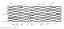
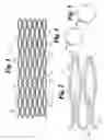
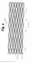
BRIEF DESCRIPTION OF THE DRAWINGFIG. 1 is an unrolled flattened plan of a stent according to a preferred form of the invention;
FIG. 2 is an enlarged portion of FIG. 1 showing in detail the loosely interlocked serpentine rings;
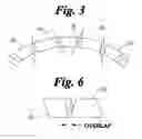
FIG. 3 is an enlarged fragmentary showing of a form of the invention having segments with angular side walls;
FIGS. 4 and 5 are end views of a stent showing their cylindrical construction and the unique cross-sectional shapes of the struts;
FIG. 6 shows overlap in stent struts, and
FIGS. 7 and 8 show portions of stents of different embodiments according to this invention.
DESCRIPTION OF THE PREFERRED EMBODIMENTSReferring to FIGS. 1 and 2, an embodiment of a stent according to the invention is shown and generally designated at 10. Stent 10 is of cylindrical or tubular configuration as can be seen in end view FIGS. 4 and 5 and includes a plurality of annular serpentine segments 12 interfitted with each other over the length of the stent body.
Each annular segment 12 is of a generally serpentine configuration having wide lateral end portions 14 and narrow lateral portions 16 spaced from ends 14, the wide portions of one ring being interfitted into the wide portion of an adjacent ring as shown to prevent longitudinal separation of the serpentine rings. Radial separation of the rings is prevented during handling and delivery by carrying the interfitted rings on a shaft (not shown) as may be provided by the delivery catheter per se.
The stents of the invention may be made of wire or the like. More preferably, they are laser cut from a metal cylinder to a desired configuration.
Historically stents have been constructed of struts with either round, square, trapezoidal, oblong, or other cross-sections. The cross-section of the strut has remained relatively constant throughout the stent. The shape of the strut has been dictated by the starting material, the cutting or shaping process, and the surface finish process. Stent designers can select from a variety of shapes to give the stent unique mechanical properties, but the stent contains the same general cross-section throughout, i.e., if the strut is oblong in shape it remains oblong, if the strut is wider on the OD than the ID it retains this profile throughout the stent. This remains true even if the cross-sectional area of the strut varies in regions of the stent.
A further improvement is shown in FIGS. 3, 4 and 5 in which segments 18 may be formed from a tube or sheet having the side walls “off center” with respect to the center line of the stent so that the segments interlock with one another if moved radially in or out. Two options are shown. FIG. 4 shows the struts laser cut off axis of the center of the stent all in the same direction. FIG. 5 shows a second option in which the off-axis direction of cut alternates around the stent.
The result is a stent which contains elements having multiple varied strut cross-sectional shapes in a predetermined manner. This attribute is desirable because each cross-sectional shape is selected to give the stent unique mechanical properties at that specific location within the stent. By either using a means to selectively remove material or mechanically deform the material, the stent struts can be formed into a tailored shape at selected locations. These tailored shapes can cause the struts to be stronger, weaker, remain flat during expansion, twist during expansion, etc.
Also, varying the cross-section of the stent struts can improve the nesting or the compaction of the struts in the compressed state. By improving the compaction properties of the stent, the stent can achieve lower profiles. There can even be overlapping regions of the various struts without actually causing struts to be deformed into the ID or OD of the stent. This helps to maintain a low profile. Additionally, the overlapping of the struts creates a securement means. Each row of struts will help to contain an adjacent row. This is shown in FIG. 6.
Referring now to FIG. 7, there is shown an example of a stent 10 in fragment to illustrate that a stent according to the invention may be made of a single elongated piece of wire or the like.
In FIG. 8, interconnections 20 are shown between rings 12 in a stent 10, showing in plan.
The above Examples and disclosure are intended to be illustrative and not exhaustive. These examples and description will suggest many variations and alternatives to one of ordinary skill in this art. All these alternatives and variations are intended to be included within the scope of the attached claims. Those familiar with the art may recognize other equivalents to the specific embodiments described herein which equivalents are also intended to be encompassed by the claims attached hereto.
Claims
What is claimed is:1-12. (canceled)
13. A flexible expandable stent comprising a plurality of serpentine structures loosely interfitted in mated relationship with adjacent serpentine structures to form a cylindrical stent body, the serpentine structures comprises a plurality of segments including wide and narrow portions, the wide portions of the serpentine structures being interfitted into the wide portions of the adjacent serpentine structures, the serpentine structures disposed helically about the stent body.
14. The stent of claim 13 in which the serpentine structures are formed of material having substantially flat sides.
15. The stent of claim 13 cut from a metal tube whereby a plurality of substantially flat sided struts in cross-section are provided.
16. The stent of claim 15 in which edges of at least some of the struts are angled with respect to the edges of adjacent struts whereby radial separation is prevented.
17. The stent of claim 13 formed of a single piece of wire.
Images & Drawings included:
Sources:
- United States Patent and Trademark Office - verify current appl. status at the USPTO↗
Similar patent applications:
- » 10108778
Flexible stent and method of making the same - » 10236144
Longitudinally flexible stent - » 9516753
Longitudinally flexible stent - » 9874335
Bifurcated axially flexible stent - » 10160531
Flexible stent - » 9797642
Flexible stent - » 9797815
Flexible stent and method of manufacture - » 9797816
Flexible stent - » 9864389
Longitudinally flexible stent - » 10321044
Flexible stent with improved axial strength
Recent applications in this class:
- » 20250288439 2025-09-18
SELF EXPANDING STENTS AND METHODS - » 20250275859 2025-09-04
LAYERED MEDICAL APPLIANCES AND METHODS - » 20250268736 2025-08-28
VASCULAR STENT AND MANUFACTURING PROCESS THEREFOR - » 20250221836 2025-07-10
SCAFFOLDS HAVING A RADIOPAQUE MARKER AND METHODS FOR ATTACHING A MARKER TO A SCAFFOLD - » 20250169972 2025-05-29
RECOLLAPSIBLE AND RECAPTURABLE DEVICES AND METHODS OF USE - » 20250120829 2025-04-17
Stent - » 20250057673 2025-02-20
LATTICE - » 20250000675 2025-01-02
MULTI-STAGE STENT DEVICES AND ASSOCIATED METHODS - » 20240398593 2024-12-05
Degradable biomedical magnesium alloy drug-eluting vascular stent and preparation method - » 20240390168 2024-11-28
Implant and Method of Making an Implant
Recent applications for this Assignee:
- » 20250288436 2025-09-18
MEDICAL IMPLANTABLE DEVICES AND METHODS OF USING THE SAME - » 20250288190 2025-09-18
MEDICAL DEVICE HANDLES, COMPONENTS, AND RELATED METHODS OF MANUFACTURING AND/OR ASSEMBLING - » 20250281727 2025-09-11
FLOW CONTROL STENT - » 20250281722 2025-09-11
FORTIFIED BALLOON INFLATION FLUID FOR PLASMA SYSTEM TO DISRUPT VASCULAR LESIONS - » 20250281719 2025-09-11
INTRODUCER SHEATH WITH A STRAIGHT LOADING SHEATH HUB - » 20250281698 2025-09-11
HYDROGEL AGITATION AND INJECTION ASSEMBLIES AND SYSTEMS - » 20250281691 2025-09-11
MEDICAL DEVICES FOR AGENT DELIVERY AND RELATED METHODS OF USE - » 20250281314 2025-09-11
STENT WITH ANTI-MIGRATION FEATURES - » 20250281274 2025-09-11
RADIAL ADJUSTING SELF-EXPANDING STENT WITH ANTI-MIGRATION FEATURES - » 20250281023 2025-09-11
SYSTEM, DEVICE AND METHOD FOR TURBIDITY ANALYSIS