Vacuum cleaner with an automatic shutdown switch assembly
US20070107158A1
2007-05-17
11/443,020
2006-05-31
Abstract:
A vacuum cleaner with an automatic shutdown switch assembly has a motor and a collector, a switch assembly, a float bracket and afloat assembly. The switch is mounted inside the vacuum cleaner and has a switch lever and a moveable magnet. The switch lever is connected to the electrical switch. The moveable magnet is mounted on the switch lever. The float bracket is mounted inside the collector. The float assembly is slidely mounted inside the float bracket and has a stationary magnet. The stationary magnet is mounted inside the float assembly. As liquid fills the collector, the float assembly floats, and the stationary magnet moves away from the moveable magnet. The moveable magnet and the stationary magnet do not repel each other so the switch lever moves away from and turns off the electrical switch and shuts down the motor.
Interested in similar patents?
Get notified when new applications in this technology area are published.
Classification:
A47L9/2889 » CPC main
Details or accessories of suction cleaners, e.g. mechanical means for controlling the suction or for effecting pulsating action; Storing devices specially adapted to suction cleaners or parts thereof; Carrying-vehicles specially adapted for suction cleaners; Installation of the electric equipment, e.g. adaptation or attachment to the suction cleaner; Controlling suction cleaners by electric means Safety or protection devices or systems, e.g. for prevention of motor over-heating or for protection of the user
A47L7/0028 » CPC further
Suction cleaners adapted for additional purposes ; Tables with suction openings for cleaning purposes; Containers for cleaning articles by suction; Suction cleaners adapted to cleaning of brushes; Suction cleaners adapted to taking-up liquids; Suction cleaners adapted to take up liquids, e.g. wet or dry vacuum cleaners; Recovery tanks Security means, e.g. float valves or level switches for preventing overflow
A47L7/0042 » CPC further
Suction cleaners adapted for additional purposes ; Tables with suction openings for cleaning purposes; Containers for cleaning articles by suction; Suction cleaners adapted to cleaning of brushes; Suction cleaners adapted to taking-up liquids; Suction cleaners adapted to take up liquids, e.g. wet or dry vacuum cleaners Gaskets; Sealing means
A47L9/2842 » CPC further
Details or accessories of suction cleaners, e.g. mechanical means for controlling the suction or for effecting pulsating action; Storing devices specially adapted to suction cleaners or parts thereof; Carrying-vehicles specially adapted for suction cleaners; Installation of the electric equipment, e.g. adaptation or attachment to the suction cleaner; Controlling suction cleaners by electric means characterised by the parts which are controlled Suction motors or blowers
A47L5/00 IPC
Suction cleaners
A47L5/00 IPC
Structural features of suction cleaners
A47L9/00 IPC
Details or accessories of suction cleaners, e.g. mechanical means for controlling the suction or for effecting pulsating action; Storing devices specially adapted to suction cleaners or parts thereof; Carrying-vehicles specially adapted for suction cleaners
Description
BACKGROUND OF THE INVENTION1. Field of the Invention
The present invention relates to a vacuum cleaner, and more particularly to an automatic shutdown switch assembly for a vacuum cleaner, which turns off the vacuum cleaner when liquid drawn into the vacuum cleaner reaches a specific level.
2. Description of Related Art
Conventional vacuum cleaners are used by many people in normal daily life to clean up dust and liquid.
The vacuum cleaner draws dust, dirt, debris and liquid into the vacuum cleaner and has a housing, a collector, a vacuum pump, a motor, electric devices, and a hose.
The housing has an inlet and an outlet.
The collector is mounted removably inside the housing near the inlet, collects and holds dust, dirt debris and liquid drawn into the vacuum cleaner by the vacuum cleaner and has a side and a window. The window is mounted in the side of the collector and allows people to see how much dust, dirt, debris or liquid is in the collector.
The vacuum pump is mounted in the housing, draws a vacuum through the vacuum pump and dust, dirt, debris or liquid into the housing through the inlet in the housing, deposits the dust, dirt, debris or liquid in the collector and has an inlet and an outlet. The inlet communicates with the inlet in the housing. The outlet communicates with the outlet in the housing
The motor is mounted inside the housing and drives the vacuum pump.
The electric devices are mounted inside the housing.
The hose is connected to the inlet in the housing so dust, dirt, debris or liquid can be drawn through the hose by the vacuum when the vacuum pump is running.
However, conventional vacuum cleaners have the following shortcomings. Specifically, failing to check the level of liquid in the collector easily results in the collector overflowing and damaging the motor and electric devices and becoming a significant electrical safety hazard when the motor and electrical devices short out.
To overcome the shortcomings, the present invention provides a vacuum cleaner with an automatic shutdown switch assembly to obviate or mitigate the aforementioned problems.
SUMMARY OF THE INVENTIONThe primary objective of the present invention is to provide a vacuum cleaner with an automatic shutdown switch assembly, which automatically turns off the vacuum cleaner when liquid inside the vacuum reaches a specific level.
The vacuum cleaner with an automatic shutdown switch assembly in accordance with the present invention has a motor, a collector a switch assembly, a float bracket and afloat assembly. The switch assembly is mounted inside the vacuum cleaner and has an electrical switch, a switch lever and a moveable magnet. The switch lever is connected to the electrical switch and turns the electrical switch on and off. The moveable magnet is mounted on the switch lever. The float bracket is mounted inside the collector. The float assembly is mounted slidably inside the float bracket and has a stationary magnet. The stationary magnet is mounted inside the float assembly. With no liquid in the collector, the stationary magnet aligns with and repels the moveable magnet and holds the switch closed. When the collector has enough liquid, the float assembly floats, the stationary magnet moves away from the moveable magnet, and the switch lever pivots away from and opens the switch. When the switch opens, the motor shuts down and stops driving the vacuum pump. Consequently, no more liquid will be drawn into the collector, and the collector cannot overflow so the motor and other components of the vacuum cannot be damaged or shorted out by the liquid.
Other objectives, advantages and novel features of the invention will become more apparent from the following detailed description when taken in conjunction with the accompanying drawings.
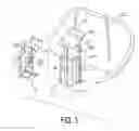
BRIEF DESCRIPTION OF THE DRAWINGSFIG. 1 is a partially exploded perspective view of a vacuum cleaner with an automatic shutdown switch assembly in accordance with the present invention;
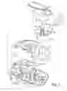
FIG. 2 is an enlarged exploded perspective view of a float assembly in a first embodiment of the automatic shutdown switch assembly in accordance with the present invention for the vacuum cleaner in FIG. 1;
FIG. 3 is an enlarged exploded perspective view of the first embodiment of the automatic shutdown switch assembly in accordance with the present invention with the float assembly aligned with a switch assembly;
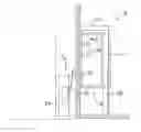
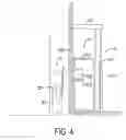
FIG. 4 is an operational side view in partial section of the automatic shutdown switch assembly in FIG. 3 with a stationary magnet in the float bracket and a moveable magnet on the switch lever repelling each other and holding the switch closed;
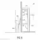
FIG. 5 is an operational side view in partial section of the automatic shutdown switch assembly in FIG. 3 with the switch open; and
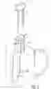
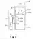
FIG. 6 is a side view in partial section of a second embodiment of the automatic shutdown switch assembly in accordance with the present invention for a vacuum when the stationary and moveable magnets repel each other.
DETAILED DESCRIPTION OF THE PREFERRED EMBODIMENTWith reference to FIGS. 1, 4 and 6, an automatic shutdown switch assembly in accordance with the present invention for a vacuum cleaner having a base (1), a motor (13), a vacuum pump (11), electric devices, a cover (2), a collector (22) and a hose comprises a switch assembly (3), a float bracket (5, 5A) and a float assembly (4, 4A).
The base (1) has an inner surface, a front end, a rear end, a motor seat, a hose hole (12) and a switch seat (33). The motor seat is formed on the top of the base (1) and near the rear end of the base (1). The hose hole (12) is formed through the base (1) near the front end and has a top end and a bottom end. The switch seat (33) is mounted on the top of the base (1) and next to the motor seat.
The motor (13) is mounted on the motor seat of the base (1).
The vacuum pump (11) is mounted on and driven by the motor (13).
The electric devices are mounted on the top of the base (1) and near the rear end of the base (1) and connected to the motor (11).
The cover (2) is mounted on the top of the base (1) and has a top, a front end, a vacuum inlet (23), a collector recess (21) and an outer cover (24). The vacuum inlet (23) is formed in the top of the cover (2). The collector recess (21) is formed in the top of the cover (2) between vacuum inlet and the front end of the cover (2) and has a bottom and a through hole. The through hole is formed through the bottom of the collector recess (21) and aligns with and holds the top end of the hose hole (12) of the base (1). The outer cover (24) is mounted on the top of the cover (2) over the vacuum inlet (23) and the collector recess (21).
The collector (22) is mounted removably in the collector recess (21) and has a reservoir and an inlet tube (221). The reservoir is formed in the collector (22) and has a bottom and a sidewall. The inlet tube (221) is formed on and extends up from the bottom of the reservoir and has a longitudinal through hole and communicates with the top end of the hose hole (12) of the base (1) so dust, dirt, debris or liquid can be drawn into the collector (22) by the vacuum generated by the vacuum pump (11).
The hose is connected to the bottom end of the hose hole (12).
The switch assembly (3) is mounted on the switch seat (33) of the base (1) and against the motor (13) and has an electrical switch (30), a switch lever (31) and a moveable magnet (32). With further reference to FIG. 5, the switch lever (31) is connected pivotally to and protrudes out and up from the electrical switch (30), closes the electrical switch (30) when the switch lever (31) is pressed toward the electrical switch (30), opens the electrical switch (30) when the switch lever (31) pivots away from the electrical switch (30) and has a proximal end and a distal end. The proximal end of the switch lever (31) is connected pivotally to the electrical switch (30). The moveable magnet (32) is attached to the switch lever (31) near the distal end and may be natural magnetite or man-made magnetite.
With further reference to FIGS. 2 and 3, the float bracket (5, 5A) is attached to the sidewall of reservoir of the collector (22), is adjacent to the switch assembly (3) and has an optional top panel (51, 51A) and three vertical sides. The top panel (51, 51A) is attached securely to and protrudes in from the sidewall of the reservoir of the collector (22) above the switch assembly (3). The vertical sides define an enclosed volume and may be implemented with at least one rod (52) or with at least one panel (52A).
The vertical sides of the float bracket (5) in a first embodiment of the automatic shutdown switch assembly in accordance with the present invention are at least one rod (52). The at least one rod (52) is mounted between the bottom of the reservoir of the collector (22) and the top panel (51). Furthermore, one or more rods (52) may be used on each side. Preferably, a total of three rods (52) are used.
The vertical sides of the float bracket (5A) in a second embodiment of the automatic shutdown switch assembly in accordance with the present invention are implemented with three panels (52A) to form a hollow box on the sidewall of the reservoir of the collector (22), and each panel has a bottom and an optional cutout (51A). The cutout (51A) is formed at bottom.
The float assembly (4, 4A) is mounted moveably in the enclosed volume between the vertical sides of the float bracket (5, 5A) and the sidewall of the reservoir of the collector (22), corresponds to the switch assembly (3) and comprises a float (41, 41A) and a stationary magnet (42). The float (41, 41A) is buoyant, may be hollow or solid, is mounted slidably in the float bracket (5, 5A) against the sidewall of the reservoir of the collector (22) and has a bottom, an outer wall, an inner wall, a magnet bracket (412, 412A) and an optional guide track (411). The magnet bracket (412, 412A) is formed on the outer wall, aligns with the moveable magnet (32) of the switch assembly (3) when the bottom of the float (41, 41A) is on the bottom of the reservoir of the collector (22) and has an outer end, an inner end and at least one opening. The opening in the magnet bracket (412) in the first embodiment of the automatic shutdown switch assembly is formed through the inner end of the magnet bracket (412). In the second embodiment of the automatic shutdown switch assembly, two openings are formed respectively through the inner end and the outer end of the magnet bracket (412A). The guide track (411) is formed vertically on and protrudes from the inner wall of the float (41) in the first embodiment of the automatic shutdown switch assembly and slidably engages a rod (52) of the float bracket (5) so that the float (41) can only float up and down in the enclosed volume in the float bracket(5).
The stationary magnet (42, 42A) is mounted securely in the magnet bracket (412, 412A) of the float (41, 41A), is aligned with the moveable magnet (32) of the switch assembly (3), repels the moveable magnet (32) of the switch assembly (3) and closes the electrical switch (30) when the bottom of the float (41, 41A) is on the bottom of the reservoir of the collector (22). In the second embodiment of the automatic shutdown switch assembly, the stationary magnet (42A) seals the magnet bracket (412A). Consequently, when the liquid fills the collector (22), the float assembly (4, 4A) floats so that and the stationary magnet (42, 42A) moves away from the moveable magnet (32). The moveable magnet (32) and the stationary magnet (42, 42A) do not repel each other so the switch lever (31) moves away from and turns off the electrical switch (30) and shuts down the motor (13).
Even though numerous characteristics and advantages of the present invention have been set forth in the foregoing description together with details of the structure and function of the invention, the disclosure is illustrative only. Changes may be made in detail especially in matters of shape, size, and arrangement of parts within the principles of the invention to the full extent indicated by the broad general meaning of the terms in which the appended claims are expressed.
Claims
What is claimed is:1. A vacuum cleaner with an automatic shutdown switch assembly comprising
a base with a switch seat;
a motor;
a collector having a reservoir with a bottom and a sidewall; and
a switch assembly mounted on the switch seat and against the motor and having
an electrical switch;
a switch lever connected pivotally to and protruding out and up from the electrical switch to close the electrical switch when the switch lever is pressed toward the electrical switch and to open the electrical switch when the switch lever pivots away from the electrical switch and having
a proximal end being connected pivotally to the electrical switch; and
a distal end; and
a moveable magnet attached to the switch lever near the distal end; and
a float bracket attached to the sidewall of the reservoir of the collector, being adjacent to the switch assembly and having three vertical sides defining an enclosed volume; and
a float assembly being mounted moveably in the enclosed volume between the vertical sides of the float bracket and the side wall of the reservoir of the collector, corresponding to the switch assembly and comprising
a float being buoyant, being mounted slidably in the float bracket against the sidewall of the reservoir of the collector and having
a bottom;
an outer wall;
an inner wall; and
a magnet bracket being formed on the outer wall, corresponding to and selectively aligning with the moveable magnet of the switch assembly and having
an outer end;
an inner end; and
at least one opening; and
a stationary magnet mounted securely in the magnet bracket of the float and aligned with the moveable magnet of the switch assembly to repel the moveable magnet of the switch assembly and close the electrical switch when the bottom of the float is on the bottom of the reservoir of the collector.
2. The vacuum cleaner as claimed in claim 1, wherein
the float bracket further has a top panel attached securely to and protruding in from the sidewall of the reservoir of the collector above the switch assembly; and
the vertical sides of the float bracket are at least one rod mounted between the bottom of the reservoir of the collector and the top panel;
3. The vacuum cleaner as claimed in claim 1, wherein
the float bracket further has a top panel attached securely to and protruding in from the sidewall of the reservoir of the collector above the switch assembly; and
the vertical sides of the float bracket are at least one panel, each vertical side having a bottom.
4. The vacuum cleaner as claimed in claim 1, wherein the float is hollow.
5. The automatic shutdown switch assembly as claimed in claim 1, wherein the moveable magnet is natural magnetite.
6. The automatic shutdown switch assembly as claimed in claim 1, wherein the moveable magnet is man-made magnetite.
7. The automatic shutdown switch assembly as claimed in claim 2, wherein the float further has a guide track formed vertically on and protruding from the inner wall of the float and slidably engaging a rod of the float bracket.
8. The automatic shutdown switch assembly as claimed in claim 2, wherein
two openings are formed respectively through the inner end and the outer end of the magnet bracket; and
the stationary magnet seals the magnet bracket.
9. The automatic shutdown switch assembly as claimed in claim 2, wherein the vertical sides are formed with three rods.
10. The automatic shutdown switch assembly as claimed in claim 3, wherein the opening in the magnet bracket is formed through the inner end of the magnet bracket.
11. The automatic shutdown switch assembly as claimed in claim 3, wherein the vertical sides of the float bracket are implemented with three panel to form a hollow box on the sidewall of the reservoir of the collector, and each panel has
a bottom; and
a cutout formed at the bottom of the panel.
Images & Drawings included:
Sources:
- United States Patent and Trademark Office - verify current appl. status at the USPTO↗
Recent applications in this class:
- » 20250169666 2025-05-29
JOYSTICK CONTROLLED FAN SPEED CONTROL FOR LEAF VACUUM - » 20250064285 2025-02-27
Vacuum Cleaner - » 20250025008 2025-01-23
STATION DEVICE ON WHICH CLEANER IS DOCKED AND OPERATING METHOD OF STATION DEVICE - » 20250025007 2025-01-23
VENTILATION ARRANGEMENT FOR A CLEANING APPARATUS - » 20240415354 2024-12-19
CORDLESS VACUUM CLEANER ADOPTING OVERHEATING PROTECTION METHOD - » 20240407616 2024-12-12
SUCTION DEVICE HAVING A COOLING DUCT AND METHOD FOR OPERAT-ING THE SUCTION DEVICE - » 20240358214 2024-10-31
ROBOT CLEANER - » 20240349967 2024-10-24
VACUUM CLEANER FOR DETECTING MOISTURE INGRESS - » 20240335077 2024-10-10
SURFACE CLEANING APPARATUS - » 20240268617 2024-08-15
CLEANER HEAD AND CLEANER COMPRISING SAME