Method for making disc flange as formed in situ in a wheel rim
US20070107222A1
2007-05-17
11/265,365
2005-11-01
Abstract:
A method for making a disc flange in a wheel rim including the steps of: A. Forming a cylinder for a wheel rim; B. Forming an annular groove concaved inwardly centripetally from a cylindrical wall of the cylinder towards an axis of the wheel rim; C. Pressing the annular groove to be an annular flattened disc flange circumferentially formed in an inside wall of the cylinder; and D. Circumferentially welding along an outer port of the flattened flange as pressed and derived from the annular groove for sealing an interior in the flattened flange; whereby upon surface treatment of the wheel rim and forming of bolt holes through the disc flange, a wheel disc can be secured to the disc flange in the wheel rim by fastening bolts through the bolt holes formed in the disc flange and in the wheel disc.
Interested in similar patents?
Get notified when new applications in this technology area are published.
Classification:
B21K23/04 » CPC further
Making other articles flanged articles
B23K20/02 » CPC further
Non-electric welding by applying impact or other pressure, with or without the application of heat, e.g. cladding or plating by means of a press ; Diffusion bonding
B23P15/00 » CPC further
Making specific metal objects by operations not covered by a single other subclass or a group in this subclass
Y10T29/49524 » CPC further
Metal working; Method of mechanical manufacture; Wheel making; Land wheel Rim making
B21K1/38 » CPC main
Making machine elements wheels; discs rims; tyres
Description
BACKGROUND OF THE INVENTIONU.S. Pat. No. 5,533,260 disclosed a method for manufacturing a vehicle wheel, in which a mounting ring (16) should be circumferentially welded to an inside wall of the wheel rim in order to secure a wheel disc (14) onto the mounting ring (16) within the wheel rim.
However, such a prior art may have the following drawbacks:
- 1. The welding position circumferentially formed in the wheel rim should be precisely positioned for welding the ring (16) in the wheel rim. Otherwise, imprecise welding of the flange in the rim may influence the wheel balance of a vehicle, thereby affecting the driving safety.
- 2. The welding for fixing the ring (16) within the rim may become inconvenient and complex as the welding must be performed in a narrow or tiny interior within the wheel rim, thereby influencing the production efficiency or increasing the cost.
- 3. For some vehicle wheels, they require two centripetal flanges respectively formed on an inner and an outer portion of a drop-center portion of a wheel rim adapted for a larger off-set and a small off-set of each wheel disc as respectively deviated from a longitudinal center plane of a wheel rim. The two flanges will require two welding operations for securing two flanges within the wheel rim, greatly increasing the production complexity and cost.
The present inventor has found the drawbacks of the prior art and invented the present method for making disc flange in situ in a wheel rim.
SUMMARY OF THE INVENTIONThe object of the present invention is to provide a method for making a disc flange in a wheel rim including the steps of:
- A. Forming a cylinder for a wheel rim;
- B. Forming an annular groove concaved inwardly centripetally from a cylindrical wall of the cylinder towards an axis of the wheel rim;
- C. Pressing the annular groove to be an annular flattened disc flange circumferentially formed in an inside wall of the cylinder; and
- D. Circumferentially welding along an outer port of the flattened flange as pressed and derived from the annular groove for sealing an interior in the flattened flange;
- whereby upon surface treatment of the wheel rim and forming of bolt holes through the disc flange, a wheel disc can be secured to the disc flange in the wheel rim by fastening bolts through the bolt holes formed in the disc flange and in the wheel disc.
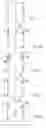
FIGS. 1A˜1E show a flow sheet for making the present invention.
FIGS. 2A˜2F show another detailed process for making the present invention.
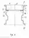
FIG. 3 is a sectional drawing for securing a wheel disc with the disc flange of the present invention.
DETAILED DESCRIPTIONAs shown in FIGS. 1A˜1E and 3, a wheel rim in accordance with the present invention is primarily formed as a cylinder 1 which is then formed with a disc flange 2 by directly forming the flange 2 in the cylinder 1. After drilling or forming bolt holes 22 through the disc flange 2, a wheel disc 5 may be secured on the flange 2 as fastened by bolts passing through the bolt holes 22 formed in the flange 2 and in the wheel disc 5.
The rim flanges 11, 12 and the drop-center portion 13 may be formed, by the conventional methods, in the wheel rim before or after forming the flange 2 of the present invention in the wheel rim, not limited in the present invention.
As shown in FIG. 1A˜1E, a general process for forming the disc flange 2 in the wheel rim is well illustrated and will be described hereinafter.
As shown in FIG. 1A, a cylinder 1 is formed by extrusion or by deep drawing process. For example, a 6061 aluminum alloy sheet may be formed as a cylindrical container by deep drawing. Then, its bottom portion is cut off to form the cylinder 1 as shown in FIG. 1A.
As shown in FIG. 1B, an annular groove 20 is concaved inwardly centripetally towards an axis O of the cylinder 1 of the wheel rim from an outside cylindrical wall of the cylinder 1 such as by rolling process. The annular groove 20 is formed as a V or U shape from a longitudinal sectional drawing of the groove 20 which is flared outwardly from the axis X of the cylinder.
As shown in FIG. 1C, the annular groove 20 is pressed (P) to be flattened to form the disc-flange 2 primarily.
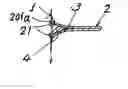
As shown in FIG. 1D, an annular welding ring 21 is circumferentially formed along an annular outer port 201 of the flattened flange 2 by welding for sealing the outer port 201 and sealing the interior in the flange 2.
As shown in FIG. 1E, the flange 2 is formed or drilled with bolt holes 22 through the flange so that plural bolts may be provided through the bolt holes 22 in the flange 2 and in the wheel disc 5 to be fastened for fixing the disc 5 on the flange 2 in the wheel rim (FIG. 3).
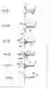
Another preferred example for more sophiscated or more detailed process of the present invention is shown in FIGS. 2A˜2F with reference to the following description.
The steps are initiated from the cylinder 1 as made in Process Step 1A (FIG. 1A) and are described as follows:
Process Step 2A (FIG. 2A:
Forming an annular groove 20 such as by rolling or concaving an outer cylindrical wall of the cylinder 1 inwardly centripetally towards an axis O in the axle center of the cylinder of the wheel rim.
Step 2B (FIG. 2B):
Pressing (P) the annular groove 20 to be flattened to form the flange 2 by repelling air outwardly through an outer port 201 circumferentially formed at an outer portion of the groove 20.
Step 2C (FIG. 2C):
Embedding or inserting a sealing element or sealant 3 and a reinforcing band 4 into the outer port 201 of the flattened flange 2.
Step 2D (FIG. 2D):
Further pressing the flange 2 and the outer port 201 (as numeral “P” shown in FIG. 2D) to squeeze, press or compress the flange 2 adjacent to the cylindrical wall of the cylinder 1 of the wheel rim to be densely contacted with the sealing element 3 and the reinforcing band 4 as sandwiched in the flattened flange 2.
Step 2E (FIG. 2E):
Forming at least one or a pair of annular welding ring(s) 21 by welding (outside the cylinder) along the outer port 201 of the flattened flange 2 by filling each annular cavity 201a (in the outer port 201) among the reinforcing band 4, the flattened flange 2 and the cylindrical wall of the cylinder 1 of the wheel rim to thoroughly seal the interior in the groove 20 of the flange 2.
Step 2F (FIG. 2F):
Polishing the outer cylindrical wall of the cylinder 1 by surface treatment and forming plural bolt holes 22 through the flange 2 adapted for securing a wheel disc 5 on the flange 2 of the wheel rim (FIG. 3).
The reinforcing band 4 may be made of aluminum alloy and the wheel rim may be made of aluminum alloy.
Besides, other processing jobs such as heat treatment, CNC processing, air leakage test, test of true circle, etc., should be done in order to well complete the production of a wheel rim having a disc flange formed therein.
The present invention discloses a method for forming a disc flange in situ in the cylinder of wheel rim.
Therefore, the present invention has the following advantages superior to the conventional arts:
- 1. Since the disc flange 2 is formed in situ in the wheel rim without performing a complex welding job as found in a conventional art, the production of wheel rim with disc flange will be simplified, inexpensive and more economic.
- 2. For making two disc flanges within a wheel rim adapted for two off-set displacements from a wheel rim center, the present invention is especially beneficial for such a purpose due to its lower production cost.
- 3. Welding ring (or rings) 21 is formed on an outer periphery of the disc flange 2 for reinforcing the mechanical strength of the flange in the wheel rim. Such a welding ring 21 will also provide a sealing effect for preventing air leakage of a wheel tire (when mounted on the wheel rim) through the bolt holes 22 as drilled in the disc flange.
The present invention may be further modified without departing from the spirit and scope of the present invention.
Claims
I claim:1. A method for forming at least a disc flange in situ in a wheel rim comprising the steps of:
A. Forming a cylinder of a wheel rim;
B. Forming an annular groove by inwardly centripetally concaving an outer cylindrical wall of said cylinder of the wheel rim towards an axis of the cylinder of the wheel rim;
C. Pressing the annular groove to be a flattened flange;
D. Forming an annular welding ring along an outer port of said flattened flange as derived from said annular groove for sealing the outer port of said flange;
whereby upon forming of a plurality of bolt holes through said disc flange, a wheel disc will be secured on said disc flange by fastening a plurality of bolts through said bolt holes formed through said disc flange and formed through the wheel disc.
2. A method according to claim 1, wherein said cylinder of said wheel rim is made by extrusion process.
3. A method according to claim 1, wherein said cylinder of said wheel rim is formed by forming a cylindrical container by a deep drawing process and then said cylindrical container is cut off a bottom portion thereof to form said cylinder of the wheel rim.
4. A method according to claim 1, wherein said annular groove is formed by a rolling process by rolling the outer cylindrical wall of the cylinder of wheel rim inwardly centripetally towards the axis of said cylinder.
5. A method according to claim 1, wherein said annular groove has its longitudinal section formed as a V shape or U shape as flared outwardly from the axis of said cylinder of wheel rim.
6. A method according to claim 1, wherein said outer port in said disc flange as derived from said annular groove is sealed by a sealing element.
7. A method according to claim 1, wherein said outer port in said flange of said wheel rim is embedded therein a reinforcing band.
8. A method according to claim 1, wherein said wheel rim is made of aluminum alloy.
9. A method according to claim 7, wherein said reinforcing band is made of aluminum alloy.
10. A method according to claim 7, wherein at least an annular welding ring is formed by welding along an annular cavity among said reinforcing band, said flange and a cylindrical wall of said wheel rim.
Images & Drawings included:
Sources:
- United States Patent and Trademark Office - verify current appl. status at the USPTO↗
Recent applications in this class:
- » 20200230692 2020-07-23
ALUMINUM ALLOYS FOR APPLICATIONS SUCH AS WHEELS AND METHODS OF MANUFACTURE - » 20190217376 2019-07-18
Aluminum wheels and methods of manufacture