Scan engine with guiding light beams
US20070108290A1
2007-05-17
11/272,855
2005-11-14
✅ Patent granted
US 7,360,704 B2
2008-04-22
-
-
Edwyn Labaze
2026-09-07
Abstract:
A method for reading symbols having data identifying characteristics is provided. The method includes the steps of: providing a nose portion that forms part of a symbol capture device. The nose portion has a plurality of spaced apart light sources that are adapted to put images on a surface. The images can be used to ascertain proper positioning and focal plane of the device.
Assignee:
- Optoelectronics Co., Ltd. 23 🇯🇵 Saitama Pref., Japan
Interested in similar patents?
Get notified when new applications in this technology area are published.
Classification:
G06K7/10732 » CPC main
Methods or arrangements for sensing record carriers, e.g. for reading patterns by electromagnetic radiation, e.g. optical sensing; by corpuscular radiation by scanning of the records by radiation in the optical part of the electromagnetic spectrum; Fixed beam scanning; Photodetector array or CCD scanning Light sources
G06K7/10811 » CPC further
Methods or arrangements for sensing record carriers, e.g. for reading patterns by electromagnetic radiation, e.g. optical sensing; by corpuscular radiation by scanning of the records by radiation in the optical part of the electromagnetic spectrum; Special measures in relation to the object to be scanned; Multidistance reading Focalisation
G06K7/10 IPC
Methods or arrangements for sensing record carriers, e.g. for reading patterns by electromagnetic radiation, e.g. optical sensing; by corpuscular radiation
G06K19/06 IPC
Record carriers for use with machines and with at least a part designed to carry digital markings characterised by the kind of the digital marking, e.g. shape, nature, code
Description
BACKGROUND OF THE INVENTION1. Field of the Invention
The present invention generally relates to symbol capture devices, and more particularly, relates to a symbol capture device or other symbol capture device with guiding light beams for ascertaining the focal length and field of view at that focal length of an image capture device.
2. Description of the Related Art
Symbol capture devices used for reading symbols having data identifying characteristics such as barcodes are known. Typically, a symbol capture device has guiding light beams for suitable positioning including the positioning of focal length and field of view. That is to say, the symbol capture device needs to be positioned relative to the symbol located at a distance at an optimal position. Known methods to determine the optimum position include using laser light sources or light emitting diodes (LED). It is important to position the device correctly, because it operates as a CCD camera or the like, and the clarity of the image and effectiveness of reading is decreased if the position is incorrect.
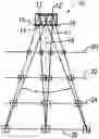
FIG. 1 shows three prior art LED projection schemes on to a surface for use in positioning the surface to be read relative to the device. The drawbacks of prior art LED schemes are that the projections do not provide a clear field of view, and there is no indication of the focal plane at which the surface to be read should be positioned.
FIG. 2 is an alternative prior art arrangement using lasers. The laser provides the same visual display to a user regardless of distance between the device and the surface of the image. While it clearly shows the field of view, the cost is relatively high. Additionally, it is difficult to ascertain the focal length. It is desirable to have a system wherein the user can easily determine the proper focal length as well as the field of view of the image capture device at that focal length. The solution should have minimal cost.
SUMMARY OF THE INVENTIONThe present invention generally provides a symbol capture device with guiding light beams for focal length and field of view determination.
The present invention further provides a symbol capture device with a set of light sources for both field of view and focal length adjustments.
The present invention further provides a symbol capture device with a light source comprising light emitting diodes (LED), without the cost of laser sources.
A method for reading symbols having data identifying characteristics is provided. The method includes the steps of: providing a nose portion that forms part of a symbol capture device. The nose portion has a plurality of spaced apart light sources that are adapted to casue a viewable image on a surface having an image to be captured. A plurality of images are generated on the surface. The focal length and the field of view of optically discernable from characteristics of the provided images.
A system for reading symbols having data identifying characteristics is provided. The system includes: a nose portion that forms part of a symbol capture device a plurality of spaced apart light sources is provided for the nose portion. The light sources are adapted to place images on a surface having the symbols formed thereon. A plurality of images are generated upon said surface as the result of the light source, and the images convey information sufficient to readily ascertain the focal plane and the field of view.
BRIEF DESCRIPTION OF THE DRAWINGSSo that the manner in which the above recited features, advantages and objects of the present invention are attained and can be understood in detail, a more particular description of the invention, briefly summarized above, may be had by reference to the embodiments thereof which are illustrated in the appended drawings.
It is to be noted, however, that the appended drawings illustrate only typical embodiments of this invention and are therefore not to be considered limiting of its scope, for the invention may admit to other equally effective embodiments.
FIG. 1 depicts a set of three prior art scan projections.
FIG. 2 depicts an alternative prior art scan projection using laser.
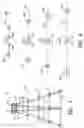
FIG. 3 depicts an optimal positioning including focal length and field of view of the present invention.
FIG. 4 is a first detailed depiction of FIG. 3.
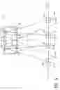
FIG. 5 is a second detailed depiction of FIG. 3.
DETAILED DESCRIPTION OF THE PREFERRED EMBODIMENTSThe present invention relates to using light emitting diodes (LEDs) and their associated lenses in a scan system for defining or adjusting to an optimal focal length and a balanced field of view. Referring to FIGS. 3-5, a preferred embodiment of the present invention is described.
Referring now to FIG. 3, an optimal positioning including focal length and field of view is shown. A symbol capture device nose portion 10 having two light emitting diodes, LED 12, LED 12′ that are positioned on a top surface is provided. LED 12 and LED 12′ are spaced apart in that a distance having a non-zero value exists between LED 12 and LED 12′. Light generated out of LED 12 radiates through lense 14 and lens 15 to form an image on any suitable surface. Similarly, light generated out of LED 12′ radiates through lense 16 and lens 17 for forming similar reflections. An imaginary assumed center axis 18 is used as a reference line. Substantially perpendicular to center axis 18 is the imaginary first surface 20. It is imaginary in that if a suitable surface is placed there, an image of the light will occur. Similarly a second surface 22, a third surface, and a fourth or optimal surface may be imagined to exist and form images thereupon. The images that would be formed on these surfaces are shown in FIG. 4, although the structure of each individual image may not be the perfect squares that are shown for explanatory purposes in FIG. 4.
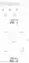
As can be seen, one of the differences among first surface 20, second surface 22, third surface 24, and fourth surface or optimal reflection surface 26 is that a different distance exists between a pair center points within image 30 and image 30′. The distances are respectively d1, d2, d3 and d4 relating to first surface 20, second surface 22, third surface 24, and fourth surface or optimal reflection surface 26 respectively. As can be seen, the value of d1, is greater than that of d2, which is greater than that of d3 and d4 is zero in that the center points of image 30 and image 30′ coincide (d1>d2>d3 and d4=0). The optimal focal length is known to be achieved when image 30 and image 30′ are adjusted to coincide (d4=0).
Because of the images 28 and 28′, the user will know the exact field of view of the device at its optimal focal plane, and can appropriately position the surface having the images to be scanned so that the image is within the field of view defined by the images 28 and 28′ and at the focal plane. In other words, the invention provides a simple method for determining both field of view and appropriate focal distance from a set of two LEDs and four lenses. The user simply places the surface to be read in front of the image capture device, and moves the surface closer to or further from the device. When images 30 and 30′ completely overlap, the surface is positioned at the focal plane for optimum image capture, and the field of view at that surface is shown by the images 28 and 28′. Those of skill in the art will recognize how to choose the lenses needed to convey the proper images.
As can be seen, in the preferred embodiment two LEDs are used. Specifically, LED 12, LED 12′ and four lenses 14-17 are used in conjunction with the two LEDs. An extra focusing lens 38 may or may not be provided for processing reflected light beam 36, 36′ and feeding the same to a light receiver 40. Light receiver 40 converts the light signal into some other type of signals such as electric signal. Light receiver 40 may comprise charge coupled device (CCD), complementary metal oxide semiconductor sensor (CMOS), or any other suitable receiver. Two beams 36, 36′ are used to define the field of view a. The two beams 32, 32′ generated by different LEDs may be concentrated by two different lenses, i.e. lens 14, lens 16 respectively. Two more beams 34, 34′ through different lenses 15, 17 but preferably from the different LEDs, i.e. LED 12, LED 12′ are used to define focal length. Furthermore, the present invention contemplates the reading of one dimensional as well as two dimensional commonly known barcode systems, and other types of images as well.
Although the foregoing description of this invention makes reference to bar code symbol capture devices, by way of example, the invention itself is equally applicable to other methods and systems for data reading and forms of encoded data (indicia) other than bar codes.
While the foregoing is directed to embodiments of the present invention, other and further embodiments of the invention may be devised without departing from the basic scope thereof, and the scope thereof is determined by the claims that follow.
Claims
What is claimed is:1. A method for reading symbols having data identifying characteristics comprising the steps of:
providing a nose portion forming part of a symbol capture device having a plurality of spaced apart light sources adapted to place images on a surface having said symbols formed thereon;
generating a plurality of such images; and
adjusting the distance between said surface and said symbol capture device such that the images take a prescribed characteristic when the surface to be read is properly positioned for reading, said prescribed characteristic ascertaining both the field of view and the focal plane.
2. The method of claim 1, wherein said prescribed characteristic is the number of such images or the distance between plural images.
3. The method of claim 2, wherein the number lenses is greater than the number of light sources such that at one light source uses more than one lenses, and wherein at least one of the images is used to ascertain the field of view of the image capture device.
4. The method of claim 1, further comprising providing lenses such that there are four images when the.
5. The method of claim 1, wherein said plurality of light sources comprises at least two light emitting diodes (LEDs).
6. The method of claim 1, wherein said plurality of images comprises four images that become three when the surface is placed at the proper focal length.
7. The method of claim 1, wherein said focal length is about one hundred millimeter (100 mm).
8. The method of claim 1, wherein said symbol capture device is a hand-held symbol capture device.
9. A barcode scanning system for reading symbols having data identifying characteristics, comprising:
a nose portion forming part of a symbol capture device having a plurality of spaced apart light sources adapted to place images on a surface having said symbols formed thereon;
a plurality of lenses and a smaller plurality of light sources arranged such that a number of images is placed by said light sources on a surface having a symbol to be captured, and wherein said number of images changes when said surface is optimally positioned for reading said symbol.
10. The system of claim 9, further comprising providing lenses for focusing lights generated by said plurality of light sources.
11. The system of claim 10, wherein the number lenses is greater than the number of light sources such that at one light source uses more than one lenses.
12. The system of claim 9, further comprising the steps of:
determining the field of view at the focal plane when said number of images changes.
13. The system of claim 9, wherein said plurality of light sources comprises at least two light emitting diodes (LEDs).
14. The system of claim 9, wherein said plurality of images decreases at the focal plane.
15. The system of claim 9, wherein said focal length is about one hundred millimeter (100 mm).
16. The system of claim 9, wherein said symbol capture device is a hand-held symbol capture device.
Images & Drawings included:
Sources:
- United States Patent and Trademark Office - verify current appl. status at the USPTO↗
Recent applications in this class:
- » 20250181858 2025-06-05
System and Method of Selective Auxiliary Data Capture - » 20250181857 2025-06-05
Methods and Systems for Light Based Accidental Scan Avoidance - » 20250173530 2025-05-29
Method and System for Reducing Perceived Illumination Flicker in Multi-Sensor Barcode Scanners - » 20250124243 2025-04-17
SYSTEM FOR READING MACHINE-READABLE LABELS ON SAMPLE RECEPTACLES - » 20250053761 2025-02-13
Devices, Systems, and Methods for Processing Indicia on Different Types of Media - » 20250036897 2025-01-30
SYSTEMS AND METHODS FOR CHANGING AN AIMER BLINK PATTERN RESPONSIVE TO A DECODE EVENT - » 20250013841 2025-01-09
AUTOMATED SYSTEM AND METHOD FOR ACQUIRING IMAGES OF ONE OR MORE CAPILLARIES IN A CAPILLARY BED - » 20240403584 2024-12-05
BI-OPTIC INDICIA READERS AND PLATTERS FOR USE THEREWITH HAVING OPTICAL REDIRECTION ELEMENT(S) WITHIN THE PLATTER - » 20240289572 2024-08-29
FORKLIFT-BASED SCANNER - » 20240281628 2024-08-22
MOBILE CODE READING DEVICE AND CODE READING METHOD
Recent applications for this Assignee:
- » 20150076232 2015-03-19
Image reading device capable of producing illumination including a continuous, low-intensity level illumination component and one or more pulsed, high-intensity level illumination components - » 20130221103 2013-08-29
Decoding method and decoding processing device - » 20130193213 2013-08-01
System and method for noise reduction in a bar code signal - » 20120037703 2012-02-16
OPTICAL DEVICE, OPTICAL INFORMATION READING DEVICE AND LIGHT SOURCE UNIT MOUNTING METHOD - » 20110210174 2011-09-01
Optical code detection with image exposure control - » 20110200314 2011-08-18
LIQUID LENS WITH TEMPERATURE COMPENSATED FOCUS TIME - » 20100302656 2010-12-02
Method and structure for mounting an optical lens - » 20100181378 2010-07-22
BEVERAGE MAKER WITH COMPACT OPTICAL CODE READER - » 20100133344 2010-06-03
Compact bar code scanner assembly - » 20080246967 2008-10-09
Apparatus for Reading a Color Symbol