Commutator for power supply testing
US20070108983A1
2007-05-17
11/309,278
2006-07-21
✅ Patent granted
US 7,312,614 B2
2007-12-25
-
-
Vincent Q. Nguyen | Hoai-An D. Nguyen
2026-07-21
Abstract:
A commutator for power supply testing includes a printed circuit board (PCB), a plurality of connectors soldered on the PCB and coupling a power supply with an electronic load, a plurality of indicator light showing whether the power supply coupled to the commutator is working, and a switch circuit. The connectors are used to couple a power supply with an electronic load. The switch circuit controls a flow of current from the power supply to the electronic load.
Assignee:
- HON HAI PRECISION INDUSTRY CO., LTD. 624 🇹🇼 Taipei Hsien, Taiwan
- HON HAI PRECISION INDUSTRY CO., LTD. 2,357 🇹🇼 Tu-Cheng, Taipei Hsien, Taiwan
- Hong Fu Jin Precision Indusrty (Shenzhen) Co., Ltd. 3 🇨🇳 Shenzhen, Guangdong Province, China
Interested in similar patents?
Get notified when new applications in this technology area are published.
Classification:
G01R31/40 » CPC main
Arrangements for testing electric properties; Arrangements for locating electric faults; Arrangements for electrical testing characterised by what is being tested not provided for elsewhere Testing power supplies
G01R31/327 IPC
Arrangements for testing electric properties; Arrangements for locating electric faults; Arrangements for electrical testing characterised by what is being tested not provided for elsewhere Testing of circuit interrupters, switches or circuit-breakers
G01R31/36 IPC
Arrangements for testing electric properties; Arrangements for locating electric faults; Arrangements for electrical testing characterised by what is being tested not provided for elsewhere Arrangements for testing, measuring or monitoring the electrical condition of accumulators or electric batteries, e.g. capacity or state of charge [SoC]
G01R11/32 IPC
Electromechanical arrangements for measuring time integral of electric power or current, e.g. of consumption; Dynamo-electric motor meters Watt-hour meters
G06F11/00 IPC
Error detection; Error correction; Monitoring
Description
FIELD OF THE INVENTIONThe present invention relates to a commutator for power supply testing.
DESCRIPTION OF RELATED ARTA typical microprocessor-cored computer system, such as a personal computer or a workstation computer, is turned on and off by a switch device that mechanically connects/disconnects a power supply of the computer system to/from an external voltage source, such as AC 110V. The power supply is connected to the external voltage source and transforms the external voltage into a predetermined DC level, such as ±5V and ±12V, and the computer system is turned on to perform various programs and functions.
As known by a person skilled with computers, the power supply mainly includes ATX power supply and BTX power supply. A motherboard of a computer can be coupled with the ATX power supply via a 20-pin ATX power connector and two 4-pin ATX power connectors. The 20-pin ATX power connector is coupled electrically with devices and a CPU socket on the motherboard through circuits thereon. One of the 4-pin ATX power connector, with four pins configured in-line, is applied to provide individual +12V/ground/ground/+5V power. Another 4-pin ATX power connector, with four pins configured in a square pattern, is applied to provide individual +12VB/ground/+12VB/ground power. The motherboard also can be coupled with the BTX power supply with a 24-pin BTX power connector, a 6-pin BTX power connector, and a 4-pin BTX power connector. The 24-pin BTX power connector is coupled electrically with devices and a CPU socket on the motherboard through circuits thereon. The 6-pin BTX power connector is applied to provide individual +12VA/ground/+12VA/ground/+12VA/ground power. The 4-pin BTX power connector, with four pins configured in a square pattern, is applied to provide individual +12VA/ground/+12VA/ground power.
However, an ATX or BTX power supply must be tested by an electronic load before being installed in a computer. Chroma programmable DC electronic load 6310 series system is suitable for testing and evaluation of multi-output AC/DC power supplies, AC/DC converters, chargers, and power electronic components and is also applicable in areas such as research and development, production, and incoming inspection. The system is configured by plugging the user selectable load modules into the system mainframe, and operated using a keypad on the front panel of the system or with remote controlled instructions via an RS-232C or GPIB interface.
The 6310 series offers 8 types of modular loads with power ranging from 30 watts to 1200 watts, current ranging from 0.5 mA to 240 mA, and voltage measurement from 0.5 mV to 500 V. Each load is isolated and floating, programmable in dual current range and measuring voltage range, and capable of synchronizing with other modules for control operation. The load can be operated as with a constant current source or a constant voltage source, with constant resistance.
What is needed is a commutator for coupling a computer power supply with an electronic load in power supply testing.
SUMMARY OF THE INVENTIONA commutator for computer power supply testing includes a printed circuit board (PCB), a plurality of connectors soldered on the PCB, a plurality of indicator lights showing whether a power supply coupled to the commutator is working, and a switch circuit. The connectors are used to couple the power supply with an electronic load. The switch circuit controls weather the current from the power supply is flowing to the electronic load.
It is simple and economical to using the commutator for coupling the power supply with the electronic load in the computer power supply testing process.
Other advantages and novel features will become more apparent from the following detailed description when taken in conjunction with the accompanying drawings, in which:
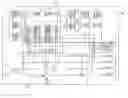
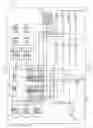
BRIEF DESCRIPTION OF THE DRAWINGSFIG. 1 is a schematic diagram of one embodiment of a commutator for testing a power supply in accordance with the present invention.
DETAILED DESCRIPTION OF THE INVENTIONReferring to FIG. 1, a commutator 10 includes a PCB 12, a plurality of connectors P1˜P10 soldered on the PCB 12, a plurality of indicator lights L1˜L8 showing whether a power supply coupled to the commutator 10 is working, and a switch circuit 1 4. The PCB 12 further includes a switch S and a power input port VIN.
The connector P1 is a 24-pin BTX power connector which is applied to provide individual +3.3V/+3.3V/−12V/+3.3V/ground/ground/PSON/+5V/ground/ground/ground/+5V/ground/ground/−5V/PG/+5V/+5VSB/+5V/+12VB/+5V/+12VB/ground/+3.3V power. The connectors P2, P3, and P4 are 4-pin ATX power connectors with four pins configured in-line. The connector P5 is a 4-pin ATX CPU power connectors with four pins configured in a square pattern. The connectors P6 and P7 are 4-pin BTX power connectors with four pins configured in-line. The connectors P6 and P7 are used to provide individual +12VA/ground/ground/+5V power. The connector P8 is a 6-pin BTX power connector. The connector P9 is a 4-pin BTX power connector with four pins configured in a square pattern. Each pin of the connectors P1˜P9 is connected to a corresponding interface of an electronic load via a signal line.
The switch circuit 14 includes a changeover switch SW1 and two transistors Q1 and Q2. A port on a side of the changeover switch SW1 is connected to ground. ON and OFF ports on another side of the changeover switch SW1 are connected to the corresponding pins PSON and +5VSB of the connector P1 respectively. A base of the transistor Q1 is connected to the ON port of the changeover switch SW1. A collector of the transistor Q1 is connected to the OFF port of the changeover switch SW1 via a capacitor C1. An emitter of the transistor Q1 is connected to the ON port of the changeover switch SW1. A base of the transistor Q2 is connected to the OFF port of the changeover switch SW1. A collector of the transistor Q2 is connected to the ON port of the changeover switch SW1. An emitter of the transistor Q2 is connected to ground.
The indicator lights L1˜L8 are light-emitting diodes (LEDs). Anodes of the indicator lights L1, L4, L5, L6, L7, and L8 are connected to corresponding pins PG, +3.3V, +5V, +12VA, +5VSB, and +12VB of the connectors P1˜P9 respectively, and cathodes of the indicator lights L1, L4, L5, L6, L7, and L8 are connected to ground. Cathodes of the indicator lights L2 and L3 are connected to corresponding pins −12V and −5V respectively, and anodes of the indicator lights L2 and L3 are connected to ground.
The switch S is a multi-way switch. A user may select any one of the +3.3V, +5V, +12VA, +12VB, +5VSB, and −12V voltages by the switch S. Ports 1˜6 of a side of the switch S are connected to the pins +3.3V, +5V, +12VA, +12VB, +5VSB, and −12V of the connector P1˜P9 respectively. Port 7 of the switch S is connected to the power input port VIN. Voltage of the power input port VIN is compared with every voltage of the ports 1˜6. If the voltage of power input port VIN is greater than the voltage selected by the switch S, the power supply is automatically turnoff.
When the commutator 10 is used to test ATX power, the changeover switch SW1 is turned to the ON port, the indicator lights L1˜L5, L7, and L8 light up. And the electronic load automatically tests the ATX power supply coupled to the commutator 10. When the commutator 10 is used to test BTX power, the changeover switch SW1 is turned to the ON port, the indicator lights L1˜L8 light up. And the electronic load automatically tests the BTX power supply coupled to the commutator 10. The indicator lights L1˜L8 indicate the PG, +3.3V, +5V, +12VA, +5VSB, and +12VB are working when lit.
It is to be understood, however, that even though numerous characteristics and advantages of the present embodiments have been set forth in the foregoing description, together with details of the structure and function of the invention, the disclosure is illustrative only, and changes may be made in detail, especially in matters of shape, size, and arrangement of parts within the principles of the invention to the full extent indicated by the broad general meaning of the terms in which the appended claims are expressed.
Claims
What is claimed is:1. A commutator for computer power supply testing, comprising:
a printed circuit board (PCB);
a plurality of connectors soldered on the PCB and coupling a power supply with an electronic load;
a plurality of indicator lights showing whether the power supply coupled to the commutator by the connectors is working; and
a switch circuit controlling a flow of current from the power supply to the electronic load.
2. The commutator as claimed in claim 1, wherein the connectors include at least one 24-pin BTX power connector, three 4-pin ATX power connectors, a 4-pin ATX CPU power connector, two 4-pin BTX power connectors, and a 6-pin BTX power connector.
3. The commutator as claimed in claim 1, wherein the switch circuit includes a changeover switch with a port connecting to ground and ON and OFF ports connecting to corresponding pins PSON and +5VSB of the connectors respectively.
4. The commutator as claimed in claim 3, wherein the switch circuit further includes two transistors.
5. The commutator as claimed in claim 4, wherein a base, a collector, and an emitter of one of the transistors are connected to the ON port of the changeover switch, the OFF port of the changeover switch, and the ON port of the changeover switch respectively, and a base, a collector, and an emitter of the other one of the transistors are connected to the OFF port of the changeover switch, the ON port of the changeover switch, and ground respectively.
6. The commutator as claimed in claim 1, wherein the indicator lights are light-emitting diodes.
7. The commutator as claimed in claim 1, wherein the PCB includes a multi-way switch and a power input port coupled to the connectors via the multi-way switch.
8. A commutator for computer power supply testing, comprising:
a printed circuit board (PCB);
a plurality of ATX power connectors and BTX power connectors soldered on the PCB and selectively coupling an ATX power supply or a BTX power supply with an electronic load;
a plurality of indicator lights showing whether the power supply coupled to the commutator by the connectors is working; and
a switch circuit controlling a flow of current from the power supply to the electronic load.
9. The commutator as claimed in claim 8, wherein the indicator lights are light-emitting diodes.
10. The commutator as claimed in claim 8, wherein the PCB includes a multi-way switch and a power input port coupled to the connectors via the multi-way switch.
Images & Drawings included:
Sources:
- United States Patent and Trademark Office - verify current appl. status at the USPTO↗
Recent applications in this class:
- » 20250290999 2025-09-18
METHODS AND APPARATUS TO DETECT AND DIAGNOSE FAULTS IN BUCK REGULATORS - » 20250290998 2025-09-18
METHOD FOR DETECTING INCORRECT INSTALLATION OF MEASUREMENT DEVICE AND ENERGY STORAGE SYSTEM USING THE SAME - » 20250283955 2025-09-11
ELECTRIC CIRCUIT HEALTH INDICATOR AND EFFICIENCY IMPROVEMENT DEVICE AND METHOD - » 20250277873 2025-09-04
Output Voltage Sense Protection Device and Method - » 20250277872 2025-09-04
CIRCUITS AND METHODS FOR SENSING CURRENT IN RESONANT TANKS OF SWITCHING POWER SUPPLIES - » 20250277871 2025-09-04
METHODS AND SYSTEMS FOR STATE OF HEALTH (SOH) MONITORING IN FUEL CELLS - » 20250271507 2025-08-28
REMAINING LIFETIME ESTIMATION METHOD FOR ELECTRONIC POWER CONVERTERS - » 20250264548 2025-08-21
SYSTEM AND METHOD FOR MATCHED-PORT POWER SUPPLY EVALUATION - » 20250258247 2025-08-14
DYNAMIC TIME WARPING (DTW)-BASED REAL-TIME DIAGNOSIS METHOD FOR COMMUTATION FAILURE (CF) OF PHASE-CONTROLLED CONVERTER - » 20250244406 2025-07-31
FAULT DETECTION IN AN ELECTRICAL POWER SYSTEM
Recent applications for this Assignee:
- » 20120147579 2012-06-14
Printed circuit board - » 20120146915 2012-06-14
NOTEBOOK COMPUTER - » 20120146343 2012-06-14
BUTTON POSITION RECTIFYING MECHANISM - » 20120145274 2012-06-14
AIR DUCT DEVICE FOR HEAT DISSIPATION - » 20110316725 2011-12-29
SCANNING CIRCUIT AND METHOD FOR KEYBOARD - » 20110294365 2011-12-01
ELASTIC ELECTRICAL CONTACT - » 20110285558 2011-11-24
Method for storing node information of Huffman tree and corresponding decoding method - » 20110232035 2011-09-29
Hinge mechanism - » 20110227465 2011-09-22
Mounting apparatus for data storage device - » 20110188245 2011-08-04
Color LED lamp having light diffusing member and hollow isolation member with concentric optical channels