Lightweight hub for rotors
US20070114798A1
2007-05-24
11/286,937
2005-11-23
✅ Patent granted
US 7,740,450 B2
2010-06-22
-
-
Edward Look | Aaron R Eastman
2029-04-20
Abstract:
A structure for a hub of a rotor includes a space frame having truss members configured to carry primary torsion, bending, and direct loading. The structure also includes a shell on the space frame configured to stabilize the space frame and carry shear loading.
Assignee:
- GENERAL ELECTRIC COMPANY 28,775 🇺🇸 Schenectady, NY, United States
Interested in similar patents?
Get notified when new applications in this technology area are published.
Classification:
F03B3/12 IPC
Machines or engines of reaction type; Parts or details peculiar thereto Blades; Blade-carrying rotors
F03D1/0658 » CPC main
Wind motors with rotation axis substantially parallel to the air flow entering the rotor ; Rotors characterised by their construction, i.e. structural design details Fixing wind-engaging parts to rotor
F03D1/0691 » CPC further
Wind motors with rotation axis substantially parallel to the air flow entering the rotor ; Rotors characterised by their construction, i.e. structural design details of the hub
F05B2230/232 » CPC further
Manufacture essentially without removing material by permanently joining parts together by welding
F05B2240/14 » CPC further
Components; Stators Casings, housings, nacelles, gondels or the like, protecting or supporting assemblies within
F05B2260/301 » CPC further
Function; Retaining components in desired mutual position Retaining bolts or nuts
F05B2280/6003 » CPC further
Materials; Properties thereof; Properties or characteristics given to material by treatment or manufacturing Composites; e.g. fibre-reinforced
F05C2253/04 » CPC further
Other material characteristics; Treatment of material Composite, e.g. fibre-reinforced
Y02E10/72 » CPC further
Energy generation through renewable energy sources; Wind energy Wind turbines with rotation axis in wind direction
Y02E10/72 » CPC further
Energy generation through renewable energy sources; Wind energy Wind turbines with rotation axis in wind direction
Y02P70/50 » CPC further
Climate change mitigation technologies in the production process for final industrial or consumer products Manufacturing or production processes characterised by the final manufactured product
Y02P70/50 » CPC further
Climate change mitigation technologies in the production process for final industrial or consumer products Manufacturing or production processes characterised by the final manufactured product
F03D9/00 IPC
Adaptations of wind motors for special use; Combinations of wind motors with apparatus driven thereby; Wind motors specially adapted for installation in particular locations
H02P9/04 IPC
Arrangements for controlling electric generators for the purpose of obtaining a desired output Control effected upon non-electric prime mover and dependent upon electric output value of the generator
Description
BACKGROUND OF THE INVENTIONThis invention relates generally to a lightweight hub structure, and more particularly to a hub structure including a space frame with truss members that is particularly suitable for use in wind turbine generators.
Monolithic shell structures with large cutouts are structurally inefficient and wasteful of material to produce. Moreover, large cutouts in monolithic shells result in stress concentrations, which further exacerbate structural inefficiency.
At least one known hub for a wind turbine includes a casting having a weight of approximately 68,000 pounds. This hub requires extensive machining to match multiple component interfaces. One known hub configuration typically has five large cutouts, including three for blade attachments, one for an output shaft, and one for a spinner. The combined weight of the hub plus the interfaced components, including pitch-drive mechanisms, can approach 100,000 pounds. Structural inefficiency equates to excessive weight, and for structures such as wind turbines that are mounted on supporting towers, these supporting towers must be designed with capacity to support the excess weight.
BRIEF DESCRIPTION OF THE INVENTIONIn one aspect, the present invention therefore provides a structure for a hub of a rotor. The structure includes a space frame having truss members configured to carry primary torsion, bending, and direct loading. The structure also includes a shell on the space frame configured to stabilize the space frame and carry shear loading.
In another aspect, the present invention provides a wind turbine for mounting on a tower. The wind turbine includes a generator, a shaft operatively coupled to the generator, a hub on the shaft, and one or more blades on the hub. The hub has a space frame having truss members configured to carry primary torsion, bending, and direct loading, and a shell on the space frame configured to stabilize the space frame and carry shear loading.
It will be appreciated that various configurations of the present invention reduce weight at the top of a wind turbine tower by utilizing a more structurally efficient hub geometry that does not compromise reliability. In addition, some configurations of the present invention reduce hub manufacturing expense by eliminating wasteful processing and manufacturing costs and the amount of raw material required for manufacture of the hub.
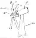
BRIEF DESCRIPTION OF THE DRAWINGSFIG. 1 is a head-on pictorial view of one configuration of the present invention.
FIG. 2 is a side pictorial view of the configuration of FIG. 1.
FIG. 3 is a view of a configuration of a wind turbine utilizing the hub configuration shown in FIGS. 1 and 2.
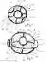
FIG. 4 is a side pictorial view of a spinner configuration suitable for the hub configuration shown in FIG. 1.
FIG. 5 is a side pictorial view of the spinner of FIG. 4 fitted onto the hub of FIG. 1, with dashed lines indicating a portion of the hub frame inside the spinner.
DETAILED DESCRIPTION OF THE INVENTIONSome configurations of the present invention provide a stiffened shell structure for improved efficiency (i.e., increased load carrying capacity per unit weight). Also, some configurations of the present invention provide a space frame configured to carry primary torsion, bending and direct loading in a truss-like manner. Also provided in some configurations is a light-weight shell configured to act as shear wall to stabilize the frame and to carry shear loading. Formed truss members in some configurations “frame” cut-outs and provide stiffer cutouts. In addition, the frame eliminates stress concentrations because the primary loading is carried by the formed frame as direct tension/compression loads rather than as membrane loading in known monolithic shells.
Forming a space frame configuration of the present invention requires less material than forming a monolithic shell. Thin shell skins in some configurations can comprise metal or a composite material. Metal shell skins are welded or bolted in place in some configurations. Composite shell skins are bolted and/or bonded in place for redundancy in some configurations of the present invention.
Thus, in some configurations of the present invention and referring to FIGS. 1, 2, and 3, a structure 10 for a hub 12 of a rotor 14 is provided. Structure 10 includes a space frame 16 having truss members 18 configured to carry primary torsion, bending, and direct loading and a meridional stiffened shell 20 on space frame 16 configured to stabilize space frame 16 and carry shear loading. Also in some configurations, truss members 18 are formed to frame cut-outs 22. Shell 20 can comprise a relatively thin metal shell 20. In configurations in which shell 20 is metal, suitable methods for attachment include, but are not limited to, welding and bolting, and combinations thereof. In some configurations, shell 20 comprises a relatively thin composite shell 20. In configurations in which shell 20 is a composite material, suitable methods for attachment include, but are not limited to, bolting and bonding (e.g., adhesive bonding), and combinations thereof.
In use, space frame 16 carries the primary loading like a truss. Shell 20 provides a shear tie and stabilizes the frame. In some configurations, five cut-outs 22 are provided and are carried by truss loading. For example, three of cut-outs 22 can be used for blades. Meridional stiffeners 21 are provided in the illustrated configuration. A load path is thus provided into a space frame in a manner reminiscent of a bridge truss. As a result, the thickness of shell 20 can be greatly reduced. The entire structure 10 can be internally cast.
In some configurations, structure 10 is a part of a wind turbine 24 that is configured for mounting on a tower 26. More particularly, wind turbine 24, in some configurations of the present invention, includes a generator (not shown) inside a nacelle 28 that resides at the top of, or on a tower 26. A shaft 30 is operatively coupled to the generator to turn the generator to generate electricity. Hub 12 is mounted on shaft 30, and one or more (for example, three) blades 32 are mounted on hub 12. Hub 12 comprises a space frame 16 having truss members 18 configured to carry primary torsion, bending, and direct loading, and a meridional stiffened shell 20 on space frame 16 configured to stabilize space frame 16 and carry shear loading. As indicated above, truss members 18 are formed to frame cut-outs 22. Cut-outs 22 are used for blade attachments 32, an output shaft 30, and a spinner 34, shown in FIGS. 4 and 5. Spinner 34 is bolted to hub 12. Shell 20 comprises a relatively thin metal, and is either welded in place, bolted in place, or both, in some configurations. In some other configurations, shell 20 comprises a composite material, and is either bolted in place, bonded in place, or both.
It will thus be appreciated that configurations of the present invention provide a structurally efficient hub that reduces weight at the top of a wind turbine without compromising reliability. In addition, hub manufacturing expense is reduced in many configurations of the present invention by eliminating wasteful processing and manufacturing costs and the amount of raw material required for manufacture of the hub.
While the invention has been described in terms of various specific embodiments, those skilled in the art will recognize that the invention can be practiced with modification within the spirit and scope of the claims.
Claims
What is claimed is:1. A structure for a hub of a rotor, said structure comprising:
a space frame having truss members configured to carry primary torsion, bending, and direct loading; and
a shell on the space frame configured to stabilize the space frame and carry shear loading.
2. A structure in accordance with claim 1 wherein the truss members are formed to frame cut-outs.
3. A structure in accordance with claim 1 wherein the shell comprises a relatively thin metal shell.
4. A structure in accordance with claim 3 wherein the shell is welded in place.
5. A structure in accordance with claim 3 wherein the shell is bolted in place.
6. A structure in accordance with claim 1 wherein the shell comprises a relatively thin composite shell.
7. A structure in accordance with claim 6 wherein the shell is bolted in place.
8. A structure in accordance with claim 6 wherein the structure is bonded in place.
9. A structure in accordance with claim 6 wherein the shell is both bolted and bonded in place.
10. A wind turbine for mounting on a tower, said wind turbine comprising:
a generator;
a shaft operatively coupled to said generator;
a hub on the shaft; and
one or more blades on the hub;
wherein the hub further comprises a space frame having truss members configured to carry primary torsion, bending, and direct loading, and a shell on the space frame configured to stabilize the space frame and carry shear loading.
11. A wind turbine in accordance with claim 10 wherein the truss members are formed to frame cut-outs.
12. A wind turbine in accordance with claim 10 wherein the shell comprises a relatively thin metal shell.
13. A wind turbine in accordance with claim 12 wherein the shell is welded in place.
14. A wind turbine in accordance with claim 12 wherein the shell is bolted in place.
15. A wind turbine in accordance with claim 10 wherein the shell comprises a relatively thin composite shell.
16. A wind turbine in accordance with claim 15 wherein the shell is bolted in place.
17. A wind turbine in accordance with claim 15 wherein the structure is bonded in place.
18. A wind turbine in accordance with claim 15 wherein the shell is both bolted and bonded in place.
Images & Drawings included:


Sources:
- United States Patent and Trademark Office - verify current appl. status at the USPTO↗
Recent applications in this class:
- » 20250067242 2025-02-27
Rotor Structure for Fluid Kinetic Power Generation Turbine - » 20250052225 2025-02-13
WIND TURBINE - » 20240360812 2024-10-31
Devices and methods for mitigating vibrations in wind turbine blades - » 20240287961 2024-08-29
Quick adjust root plate attachment for wind turbine blade molds - » 20240068436 2024-02-29
METHOD OF JOINING BLADE SEGMENTS USING AN INTERNAL BLADDER - » 20240035439 2024-02-01
Blade apparatus for wind power generation and wind power generation device - » 20230366371 2023-11-16
Wind turbine blade assembly and methods - » 20230296075 2023-09-21
Fastener assembly, wind turbine hub assembly and related methods - » 20230287862 2023-09-14
ROOT BUSHING, WIND TURBINE ROTOR BLADE AND METHOD - » 20230073360 2023-03-09
Insert for a wind turbine blade root
Recent applications for this Assignee:
- » 20250250942 2025-08-07
Overall Engine Efficiency Rating for Turbomachine Engines - » 20250243827 2025-07-31
MULTIPLE-FLOW AIRCRAFT TURBINE ENGINE - » 20250229333 2025-07-17
SYSTEMS AND METHODS FOR SMOOTHING A CONTOUR OF AN OBJECT FORMED DURING ADDITIVE MANUFACTURING - » 20250224115 2025-07-10
TURBINE ENGINE HAVING A COMBUSTION SECTION WITH A FUEL SUPPLY ASSEMBLY - » 20250223929 2025-07-10
UNDUCTED PROPELLER GAS TURBINE COMPRISING A COOLING AIR CHANNEL AND A VARIABLE BLEED VALVE EJECTION CHANNEL - » 20250222519 2025-07-10
ADDITIVE MANUFACTURING SUPPORTS AND METHODS FOR USING SAME IN ADDITIVELY MANUFACTURING PARTS - » 20250215830 2025-07-03
SUSPENSION OF A TRIPLE-FLOW AIRCRAFT TURBINE ENGINE - » 20250215826 2025-07-03
GAS TURBINE ENGINE - » 20250215811 2025-07-03
SYSTEMS AND METHODS FOR ATTACHMENT OF MATERIALS HAVING DIFFERENT THERMAL EXPANSION COEFFICIENTS - » 20250207534 2025-06-26
GAS TURBINE ENGINES AND EPICYCLIC GEARBOXES WITH PLANET GEAR CLEARANCES