Oblique transmission illumination inspection system and method for inspecting a glass sheet
US20070115463A1
2007-05-24
11/284,754
2005-11-21
✅ Patent granted
US 7,283,227 B2
2007-10-16
-
-
Sang H. Nguyen
2026-01-18
Abstract:
An oblique illumination inspection system and method are described herein that are used to identify a defect (e.g., inclusion, onclusion, scratch, stain, blister, cord or other imperfection associated with a surface discontinuity or material non-homogeneity) on or within a glass sheet (e.g., LCD glass substrate).
Assignee:
- CORNING INCORPORATED 5,381 🇺🇸 Corning, NY, United States
Interested in similar patents?
Get notified when new applications in this technology area are published.
Classification:
G01N21/00 IPC
Investigating or analysing materials by the use of optical means, i.e. using sub-millimetre waves, infrared, visible or ultraviolet light
G01N21/958 » CPC main
Investigating or analysing materials by the use of optical means, i.e. using sub-millimetre waves, infrared, visible or ultraviolet light; Systems specially adapted for particular applications; Investigating the presence of flaws or contamination characterised by the material or shape of the object to be examined Inspecting transparent materials or objects, e.g. windscreens
G01B11/0608 » CPC further
Measuring arrangements characterised by the use of optical means for measuring length, width or thickness for measuring thickness ; e.g. of sheet material Height gauges
G01N21/4788 » CPC further
Investigating or analysing materials by the use of optical means, i.e. using sub-millimetre waves, infrared, visible or ultraviolet light; Systems in which incident light is modified in accordance with the properties of the material investigated; Scattering, i.e. diffuse reflection Diffraction
G01N21/45 » CPC further
Investigating or analysing materials by the use of optical means, i.e. using sub-millimetre waves, infrared, visible or ultraviolet light; Systems in which incident light is modified in accordance with the properties of the material investigated; Refractivity; Phase-affecting properties, e.g. optical path length using interferometric methods; using Schlieren methods
G01N2021/8822 » CPC further
Investigating or analysing materials by the use of optical means, i.e. using sub-millimetre waves, infrared, visible or ultraviolet light; Systems specially adapted for particular applications; Investigating the presence of flaws or contamination; Specially adapted optical and illumination features Dark field detection
G01N2021/8854 » CPC further
Investigating or analysing materials by the use of optical means, i.e. using sub-millimetre waves, infrared, visible or ultraviolet light; Systems specially adapted for particular applications; Investigating the presence of flaws or contamination; Scan or image signal processing specially adapted therefor, e.g. for scan signal adjustment, for detecting different kinds of defects, for compensating for structures, markings, edges Grading and classifying of flaws
Description
BACKGROUND OF THE INVENTION1. Field of the Invention
The present invention relates to an oblique illumination inspection system and method for identifying defects on or within a glass sheet.
2. Description of Related Art
Manufacturers of glass sheets are always trying to design a new and improved inspection system that can be used to identify defects (e.g., scratches, stains, particle inclusions) that are on or within a glass sheet (e.g., liquid crystal display (LCD) glass substrate). One type of inspection system that is currently being used today relies on a bright field illumination technique to detect, characterize, and classify defects on or within the glass sheet. This type of inspection system is described below with respect to FIG. 1 (PRIOR ART).
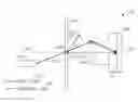
Referring to FIG. 1 (PRIOR ART), there is shown a traditional bright field illumination inspection system 100 that is currently used to inspect a glass sheet 102 and identify defects 104 (one shown) on or within the glass sheet 102. The inspection system 100 includes a light source 106 (e.g., fiber line light source 106) and a CCD camera 108. The light source 106 and CCD camera 108 are located on opposite sides of the glass sheet 102, and the light source 106 is located on an optic axis 110 of the CCD camera 108. In operation, the light source 106 emits a light beam 112 which passes through a portion of the glass sheet 102. As shown, the CCD camera 108 and in particular a camera lens 109 receives direct light 112 that passed un-deviated through the transparent defect 104. In addition, the CCD camera 108/camera lens 109 receives light 112a (D+) and 112a (D−) that was diffracted by the transparent defect 104. The camera lens 109 focuses the light 112, 112a (D+) and 112a (D−) onto an image plane 111 within the CCD camera 108. The CCD camera 108 then creates an image which is used to detect, characterize and classify the defect 104.
Although this type of lighting affords a compact design and employs industry standard lighting techniques, the image contrast of certain transparent glass defects, such as silica, scratches, and stains, is relatively poor (see FIG. 5). The poor image contrast hinders the characterization and classification of the transparent defect 104, which adversely impacts the quality of the inspection process. This poor image contrast is primarily due to the interference between the light 112 that passed un-deviated through the transparent defect 104 and the light 112a (D+) and 112a (D−) that was diffracted by the transparent defect 104. In this configuration, light 112a (D+) and 112a (D−) respectively have a positive diffraction order D+ and a negative diffraction order D− both of which interfere with the un-deviated light 112 to essentially wash out the contrast of the transparent defect 104 in the image. The two problematic diffraction orders D+ and D− are present because of the symmetry in the bright field lighting technique (i.e. the light source 106 is located on the optic axis 110 of the CCD camera 108). The resulting poor image contrast and other shortcomings associated with the bright field illumination inspection system 100 are addressed by the present invention.
BRIEF DESCRIPTION OF THE INVENTIONThe present invention includes an inspection system which uses an oblique illumination technique where the illumination symmetry is broken between the light source(s) and the CCD camera. This enhances the quality of the image. In addition, this type of inspection system enables one to indirectly extract the height of a glass surface discontinuity from the image. Thus, the need for using an additional glass surface discontinuity height sensor is eliminated.
BRIEF DESCRIPTION OF THE DRAWINGSA more complete understanding of the present invention may be had by reference to the following detailed description when taken in conjunction with the accompanying drawings wherein:
FIG. 1 (PRIOR ART) is a diagram illustrating the basic components of a traditional bright field illumination inspection system;
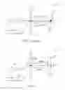
FIG. 2 is a diagram illustrating the basic components of an oblique illumination inspection system in accordance with a first embodiment of the present invention;
FIG. 3 is a diagram illustrating the basic components of an oblique illumination inspection system in accordance with a second embodiment of the present invention;
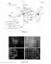
FIG. 4 illustrates several images of defects that where obtained by using the oblique illumination inspection system shown in FIG. 3 in accordance with the present invention;
FIG. 5 has several images of defects obtained by using the traditional bright field illumination inspection system shown in FIG. 1 and several images of the same defects that where obtained by using the oblique illumination inspection system shown in FIG. 3 in accordance with the present invention; and
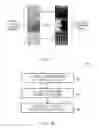
FIG. 6 is a flowchart illustrating the basic steps of a preferred method for inspecting a glass sheet in accordance with the present invention.
DETAILED DESCRIPTION OF THE DRAWINGSThe present invention addresses the image contrast problem that is associated with the known bright field illumination inspection system 100 by breaking the symmetry of the lighting which occurs when the light source 106 is placed on the optic axis 110 of the CCD camera 108 (see FIG. 1). The symmetry may be broken by using an oblique illumination technique (anaxial illumination technique) in which one or more light sources is/are not placed on the optic axis of the CCD camera. Two exemplary oblique illumination inspection systems 200 and 300 are described next with respect to FIGS. 2 and 3.
Referring to FIG. 2, there is shown an oblique illumination inspection system 200 that can be used to inspect a glass sheet 202 and identify defects 204 (one shown) on or within the glass sheet 202. The inspection system 200 includes a light source 206 (e.g., fiber line light source 206) and a CCD camera 208. The light source 206 and CCD camera 208 are located on opposite sides of the glass sheet 202, while the light source 206 is located off the optic axis 210 of the CCD camera 208 (this achieves the illumination symmetry breaking). In operation, the light source 206 emits a light beam 212 which passes through a portion of the glass sheet 202. The CCD camera 208 and in particular a camera lens 209 receives light 212 that passed un-deviated through the transparent defect 204. In addition, the CCD camera 208/camera lens 209 receives light 212a (D−) that was diffracted by the transparent defect 204. However, the CCD camera 208/camera lens 209 do not receive light 212a (D+). The camera lens 209 focuses light 212 and 212a (D−) onto an image plane 211 within the CCD camera 208. The CCD camera 108 then creates a high contrast image which is used to detect, characterize and classify the defect 204 (see FIGS. 4 and 5).
The oblique illumination technique results in an image which has a much higher contrast of transparent glass defects, such as silica, scratches, and stains when compared to the known bright field illumination technique (see FIG. 5). As discussed above with respect to FIG. 1 (PRIOR ART), the symmetrical bright field illumination inspection system 100 generates an image that has a poor contrast because of the interference between the light 112 that passes un-deviated through the transparent defect 104 and the light 112a (D+) and 112a (D−) that was diffracted by the transparent defect 104. In particular, light 112a (D+) and 112a (D−) respectively have a positive diffraction order D+ and a negative diffraction order D− both of which interfere with the un-deviated light 112 to essentially wash out the contrast of the transparent defect 104 in the image.
This is not a problem with the oblique illumination technique, because the illumination symmetry is broken by offsetting the light source 206 from the optic axis 210 of the CCD camera 208. In particular, in the oblique illumination technique one of the complementary diffraction orders of the diffracted light 212a (D+) and 212a (D−) is suppressed and only the remaining diffraction order shown in this example as light 212a (D−) is allowed to interfere with the un-deviated light 212a. This results in an image being generated which has a contrast that is much higher than an image obtained by the symmetrical bright field illumination inspection system 100 (see FIG. 5).
Referring to FIG. 3, there is shown another oblique illumination inspection system 300 that can be used to inspect a glass sheet 302 and identify defects 304 (one shown) on or within the glass sheet 302. The inspection system 300 includes a primary light source 306a (e.g., primary fiber line light source 306a), a secondary light source 306b (e.g., secondary fiber line light source 306b), and a CCD camera 308. The primary and secondary light sources 306a and 306b are located on one side of the glass sheet 302, while the CCD camera 308 is located on the opposite side of the glass sheet 302. As can be seen, both light sources 306a and 306b are offset from an optic axis 310 of the camera 308. The primary light source 306a is located closer to the optic axis 310 than the secondary light source 306b. As a result, the primary light source 306a provides a slow directional gradient illumination across a field of view 314 of the CCD camera 308 and is responsible for most of the image contrast enhancement. The secondary light source 306b provides a more balanced illumination across the field of view 314 in the CCD camera 308 and is responsible for image enhancement of the edges of the defect 304.
In operation, the light sources 306a and 306b respectively emit light beams 316 and 318 which pass through a portion of the glass sheet 302. The CCD camera 308 and in particular a camera lens 309 receives light 316 that passed un-deviated through the transparent defect 304. In addition, the CCD camera 308/camera lens 309 receives light 316a (D1−) that was diffracted by the transparent defect 204. Moreover, the CCD camera 308/camera lens 309 receives light 318a (D2+) that was diffracted by the transparent defect 204. However, the CCD camera 308/camera lens 309 does not receive light 316a (D1+), 318 and 318a (D2−). The camera lens 209 then focuses light 316, 316a (D1−) and 318a (D2+) onto an image plane 311 within the CCD camera 308. The CCD camera 108 then creates a high contrast image which is used to detect, characterize and classify the defect 304 (see FIGS. 4 and 5). If only one light source 206 is used as is the case with the oblique illumination inspection system 200, then there will be an intensity gradient across the field of view 214 in the CCD camera 208. This is necessary to develop the contrast enhancement effect. However, this gradient needs to be removed by software during the processing of the image. In contrast, if two light sources 306a and 306b are used as is the case with the oblique illumination inspection system 300, then this gradient is lessened to some degree such that software may not be needed to remove it during the processing of the image.
An advantage of the oblique illumination technique over the traditional bright field illumination technique is that the image contrast and resolution are enhanced. For instance, glass surface defects 204 and 304 such as scratches, stains, and onclusions which appear two dimensional under the standard bright field illumination technique now appear three dimensional under the oblique illumination technique of the present invention. This added dimensionality allows a human operator who is inspecting the glass sheet 202 and 302 to make a more accurate defect classification judgment. In turn, a more accurate defect classification judgment results in fewer glass sheets 202 and 302 being falsely rejected as defective. Thus, the quality of the inspection process is improved.
Referring to FIG. 4, there are illustrated several images of surface defects which were obtained when testing the oblique illumination inspection system 300. As can be seen, the images clearly indicate the three dimensional nature of the various defects 304. These images have a much better quality than the images obtained by the known bright field illumination technique in which stains and particles would appear nearly invisible or opaque. A comparison of the differences between images obtained by the traditional bright field illumination inspection system 100 and images obtained by the oblique illumination inspection system 300 can be made by looking at the photos of FIG. 5. As can be seen, the silica/platinum defects are barely visible in the bright field images which were obtained by the traditional bright field illumination inspection system 100. While, the same silica/platinum defects are clearly visible in the gradient field images which were obtained by the oblique illumination inspection system 300.
Another advantage of the oblique illumination technique over the traditional bright field illumination technique is that the oblique illumination technique enables one to qualitatively measure the height of a surface discontinuity which is caused by a defect 204 and 304 embedded within the glass sheet 202 and 302. The height of the surface discontinuity can be indirectly calculated by analyzing the contrast variations (modulations) around the defect 204 and 304 in the surface defect image (see FIG. 5). In particular, the height of the surface discontinuity can be measured by: (1) determining the intensity of light on the left side of the defect 204 and 304 in the surface defect image; (2) determining the intensity of light on the right side of the defect 204 and 304 in the surface defect image; and (3) comparing the first intensity and the second intensity to determine a difference in intensities which is directly related to the height of the surface discontinuity.
The ability to qualitatively measure the height of a surface discontinuity using the present invention is a marked-improvement over the traditional bright field illumination inspection system 100, because, the bright field illumination inspection system 100 does not generate an image that enables one to qualitatively measure the height of a surface discontinuity. Instead, an additional off-line surface discontinuity height sensor would be needed to make this height measurement, which would slow down the defect inspection process. The oblique illumination inspection system 200 and 300 eliminates the need for using a separate surface discontinuity height sensor. This saves money and increases the speed at which the glass sheets 202 and 302 can be inspected.
Referring to FIG. 6, there is a flowchart illustrating the basic steps of a preferred method 600 for inspecting a glass sheet 202 and 302 in accordance with the present invention. Beginning at step 602, the light sensors 206, 306a and 306b (which form an oblique illumination system) are used to illuminate at least a portion of the glass sheet 202 and 302. At step 604, the CCD camera 208 and 308 is used to generate an image of at least a portion of the illuminated portion of the glass sheet 202 and 302. Then, the image is analyzed to detect, characterize and classify a defect 204 and 304 (if any) in the glass sheet 202 and 302. In the preferred embodiment, the image may be analyzed in a manner that removes camera noise (pixel variation, dust, etc.) and lighting gradients. In addition, the image may be analyzed to remove unwanted particles (e.g., based on size) and auto measure the size of the remaining defects 204 and 304.
Following are some additional features, advantages and uses of the oblique illumination technique of the present invention:
-
- Manufacturers of glass sheets (glass substrates) which are incorporated into LCD display products would benefit from the use of the oblique illumination inspection system 200 and 300. Since, these glass sheets must be free from defects such as scratches, stains, and particle inclusions. The manufacturer could use the inspection system 200 and 300 to inspect the glass sheets while they are on the production finishing line before they are packed and shipped to a customer who assembles the LCD display products.
- The inspection systems 200 and 300 described herein use an oblique transmission illumination technique to enhance image contrast over that of the traditional bright field illumination inspection systems. It should be noted that there are several other contrast enhancing techniques which can be used in addition to oblique illumination. Some of these techniques are as follows:
- Coherent illumination.
- Phase contrast illumination.
- Differential interference contrast illumination.
- Single sideband edge enhancement microscopy.
- The inspection systems 200 and 300 can detect, characterize and classify many different types of defects 204 and 304 including an inclusion, an onclusion, a scratch, a stain, a blister, a cord, or a surface discontinuity (for example).
- The glass sheets 202 and 302 described above can be made in accordance with a fusion process that is described in U.S. Pat. Nos. 3,338,696 and 3,682,60. The contents of these patents are incorporated herein by reference.
Although two embodiments of the present invention have been illustrated in the accompanying Drawings and described in the foregoing Detailed Description, it should be understood that the invention is not limited to the embodiments disclosed, but is capable of numerous rearrangements, modifications and substitutions without departing from the spirit of the invention as set forth and defined by the following claims.
Claims
What is claimed is:1. An inspection system, comprising:
an oblique illumination system that illuminates at least a portion of a glass sheet; and
a camera that generates an image of at least a portion of the illuminated portion of the glass sheet, wherein said image enables one to detect, characterize and classify a defect in the glass sheet.
2. The inspection system of claim 1, wherein said oblique illumination system is a single source off axis transmission light system.
3. The inspection system of claim 1, wherein said oblique illumination system is a dual source off axis transmission light system.
4. The inspection system of claim 1, wherein said defect is:
an inclusion;
an onclusion;
a scratch;
a stain;
a blister;
a cord; or
a surface discontinuity.
5. The inspection system of claim 1, wherein said image indicates the defect in three dimensions.
6. The inspection system of claim 1, wherein said image enables one to indirectly measure a height of a surface discontinuity which is caused if the defect is embedded within the glass sheet.
7. An oblique illumination inspection system, comprising:
a light source capable of emitting a light beam which passes through at least a portion of a glass sheet; and
a camera, which has an optic axis that is offset from said light source, capable of generating an image of the illuminated portion of the glass sheet where the image is used to detect, characterize and classify one or more defects in the glass sheet.
8. The oblique illumination inspection system of claim 7, wherein if there is a defect in the glass sheet then said camera receives undeviated light and either a positive diffracted light or a negative diffracted light from said light source.
9. The oblique illumination inspection system of claim 7, wherein said defect is:
an inclusion;
an onclusion;
a scratch;
a stain;
a blister;
a cord; or
a surface discontinuity.
10. The oblique illumination inspection system of claim 7, wherein said image indicates the defect in three dimensions.
11. The oblique illumination inspection system of claim 7, wherein said image enables one to indirectly measure a height of a surface discontinuity which is caused if the defect is embedded within the glass sheet.
12. The oblique illumination inspection system of claim 11, wherein the height of the surface discontinuity is indirectly measured by:
determining a first intensity of light at a first side of the defect in the image;
determining a second intensity of light at a second side of the defect in the image; and
comparing the first intensity and the second intensity to determine a difference in intensities which is directly related to the height of the surface discontinuity.
13. An oblique illumination inspection system, comprising:
a primary light source capable of emitting a first light beam which passes through a portion of a glass sheet;
a secondary light source capable of emitting a second light beam which passes through the portion of the glass sheet; and
a camera, which has an optic axis that is offset from said primary light source and said secondary light source, capable of of generating an image of the illuminated portion of the glass sheet where the image is used to detect, characterize and classify a defect in the glass sheet.
14. The oblique illumination inspection system of claim 13, wherein:
said primary light source is located relatively close to the optic axis of said camera; and
said secondary light source is located relatively far from the optic axis of said camera.
15. The oblique illumination inspection system of claim 14, wherein if there is a defect in the glass sheet then said camera receives undeviated light and either a positive diffracted light or a negative diffracted light from said primary light source and said camera also receives either a positive diffracted light or a negative diffracted light from said secondary light source.
16. The oblique illumination inspection system of claim 13, wherein:
said primary light source provides a relatively slow directional gradient illumination across a field of view in said camera; and
said secondary light source provides a relatively balanced directional gradient illumination across the field of view in said camera.
17. The oblique illumination inspection system of claim 13, wherein said defect is:
an inclusion;
an onclusion;
a scratch;
a stain;
a blister;
a cord; or
a surface discontinuity.
18. The oblique illumination inspection system of claim 13, wherein said image indicates the defect in three dimensions.
19. The oblique illumination inspection system of claim 13, wherein said image enables one to indirectly measure a height of a surface discontinuity which is caused if the defect is embedded within the glass sheet.
20. The oblique illumination inspection system of claim 19, wherein the height of the surface discontinuity is indirectly measured by:
determining a first intensity of light at a first side of the defect in the image;
determining a second intensity of light at a second side of the defect in the image; and
comparing the first intensity and the second intensity to determine a difference in intensities which is directly related to the height of the surface discontinuity.
21. A method for inspecting a glass sheet, said method comprising the steps of:
using an oblique illumination system to illuminate at least a portion of a glass sheet;
using a camera to generate an image of at least a portion of the illuminated portion of the glass sheet; and
analyzing said image to detect, characterize and classify a defect in the glass sheet.
22. The method of claim 21, wherein said oblique illumination system is a single source off axis transmission light system.
23. The method of claim 21, wherein said oblique illumination system is a dual source off axis transmission light system.
24. The method of claim 21, wherein said defect is:
an inclusion;
an onclusion;
a scratch;
a stain;
a blister;
a cord; or
a surface discontinuity.
25. The method of claim 21, wherein said image indicates the defect in three dimensions.
26. The method of claim 21, further comprising the step of analyzing said image to indirectly measure a height of a surface discontinuity which is caused if the defect is embedded within the glass sheet, wherein said analyzing step further includes:
determining a first intensity of light at a first side of the defect in the image;
determining a second intensity of light at a second side of the defect in the image; and
comparing the first intensity and the second intensity to determine a difference in intensities which is directly related to the height of the surface discontinuity.
Images & Drawings included:
Sources:
- United States Patent and Trademark Office - verify current appl. status at the USPTO↗
Recent applications in this class:
- » 20250137939 2025-05-01
VERIFICATION METHOD FOR A BIRD PROTECTION FUNCTION OF A GLASS SURFACE - » 20250085236 2025-03-13
ANALYSIS DEVICE FOR CONDITION MONITORING OF A PROTECTIVE GLASS OF A MANUFACTURING FACILITY AND A MANUFACTURING FACILITY FOR AN ADDITIVE MANUFACTURING PROCESS - » 20250052692 2025-02-13
A METHOD AND SYSTEM FOR DISCRIMINATING DEFECTS PRESENT ON A FRONTSIDE FROM DEFECTS PRESENT ON A BACKSIDE OF A TRANSPARENT SUBSTRATE - » 20240402095 2024-12-05
PROTECTIVE GLASS CONTAMINATION DETECTION DEVICE AND PROTECTIVE GLASS CONTAMINATION DETECTION METHOD - » 20240337609 2024-10-10
INSPECTION DEVICE - » 20240280509 2024-08-22
METHOD FOR DETECTING OPTICAL DEFECTS WITHIN WINDSHIELD - » 20240219318 2024-07-04
Exterior aircraft light with cover erosion monitoring, aircraft comprising such exterior aircraft light, and method of monitoring erosion of a light transmissive cover - » 20240142391 2024-05-02
INSPECTION METHOD FOR DISPLAY DEVICE - » 20240094145 2024-03-21
Detection method and system for determining the location of a surface defect on a front or back surface of a transparent film - » 20240053281 2024-02-15
Real-time detection of deflections and ruptures of EUV pellicle membranes
Recent applications for this Assignee:
- » 20250060643 2025-02-20
CHOLESTERIC LIQUID CRYSTAL WINDOW HAVING MULTIPLE STABLE STATES AND METHODS FOR USE - » 20250051214 2025-02-13
PRECURSOR GLASSES AND GLASS-CERAMICS COMPRISING A CRYSTALLINE PHASE HAVING A JEFFBENITE CRYSTALLINE STRUCTURE - » 20250042804 2025-02-06
HIGH STRENGTH GLASS-CERAMICS - » 20240414814 2024-12-12
Electrical heaters for exhaust aftertreatment systems and assemblies - » 20240400440 2024-12-05
Coating of glass-based assembly - » 20240387863 2024-11-21
Doped-zirconia ceramic ribbon - » 20240368031 2024-11-07
METHOD OF MANUFACTURING FLEXIBLE COVER WINDOW AND FLEXIBLE COVER WINDOW MANUFACTURED USING SAME - » 20240366474 2024-11-07
GLASS CONTAINERS FOR STORING PHARMACEUTICAL COMPOSITIONS - » 20240319458 2024-09-26
INTEGRATED CIRCUIT PACKAGES HAVING ELECTRICAL AND OPTICAL CONNECTIVITY AND METHODS OF MAKING THE SAME - » 20240317639 2024-09-26
TEXTURED, ANTIGLARE GLASS ARTICLES AND METHODS OF MAKING THE SAME