Cutting blade that can be rotationally driven
US20070119285A1
2007-05-31
11/614,303
2006-12-21
✅ Patent granted
US 9,102,072 B2
2015-08-11
-
-
Omar Flores Sanchez
Gifford, Krass, Sprinkle, Anderson & Citkowski, P.C.
2030-08-12
Abstract:
The invention relates to a cutting blade that can be rotationally driven in which a stabilization area provided in the form of at least one bulge is provided between a central fixing area and an edge area whose outer periphery is provided in the form of a cutting edge.
Assignee:
- Weber Maschinenbau Gmbh & Co. Kg 5 🇩🇪 Breidenbach, Germany
- Weber Maschinenbau GmbH & Co. KG 5 🇩🇪 Breidenbach, Germany
Applicant:
Interested in similar patents?
Get notified when new applications in this technology area are published.
Classification:
Y10T83/6492 » CPC further
Cutting; With means to convey work relative to tool station Plural passes of diminishing work piece through tool station
Y10T83/929 » CPC further
Cutting Tool or tool with support
Y10T83/9372 » CPC further
Cutting; Tool or tool with support Rotatable type
B02C18/20 IPC
Disintegrating by knives or other cutting or tearing members which chop material into fragments with rotating knives; Details; Knives; Mountings thereof Sickle-shaped knives
B26D1/29 IPC
Cutting through work characterised by the nature or movement of the cutting member or particular materials not otherwise provided for ; Apparatus or machines therefor; Cutting members therefor involving a cutting member which does not travel with the work having a cutting member moving about an axis with a non-circular cutting member moving about an axis substantially perpendicular to the line of cut and rotating continuously in one direction during cutting with cutting member mounted in the plane of a rotating disc, e.g. for slicing beans
A47J43/07 IPC
Implements for preparing or holding food, not provided for in other groups of this subclass; Machines for domestic use not covered elsewhere, e.g. for grinding, mixing, stirring, kneading, emulsifying, whipping or beating foodstuffs, e.g. power-driven Parts or details, e.g. mixing tools, whipping tools
B26D1/00 IPC
Cutting through work characterised by the nature or movement of the cutting member or particular materials not otherwise provided for ; Apparatus or machines therefor; Cutting members therefor
B26D1/12 IPC
Cutting through work characterised by the nature or movement of the cutting member or particular materials not otherwise provided for ; Apparatus or machines therefor; Cutting members therefor involving a cutting member which does not travel with the work having a cutting member moving about an axis
B26D1/0006 » CPC main
Cutting through work characterised by the nature or movement of the cutting member or particular materials not otherwise provided for ; Apparatus or machines therefor; Cutting members therefor Cutting members therefor
B26D2001/0046 » CPC further
Cutting through work characterised by the nature or movement of the cutting member or particular materials not otherwise provided for ; Apparatus or machines therefor; Cutting members therefor; Cutting members therefor rotating continuously about an axis perpendicular to the edge
B26D2001/0053 » CPC further
Cutting through work characterised by the nature or movement of the cutting member or particular materials not otherwise provided for ; Apparatus or machines therefor; Cutting members therefor; Cutting members therefor having a special cutting edge section or blade section
Description
CROSS-REFERENCE TO RELATED APPLICATIONSThis application is a continuation-in-part of U.S. patent application Ser. No. 10/495,006 filed Oct. 4, 2004, which is a 371 of PCT/EP02/12590 filed Nov. 11, 2002, which claims priority of German Patent Application No. 10155048.0 filed Nov. 9, 2001.
BACKGROUND OF THE INVENTIONI. Field of the Invention
The present invention relates to a cutting blade of the type used in food slicers.
II. Description of Related Art
Very high demands with respect to stiffness and strength are made on blades which are in particular used with so-called slicers for the slicing of food products such as ham, sausage, cheese and the like. These demands have the consequence that these blades have to be made in expensive manufacturing processes and have a relatively high weight.
SUMMARY OF THE INVENTIONIt is the object of the invention to provide a blade for food slicers which is characterized by higher stiffness with simultaneously lower weight with respect to conventional blades and which can moreover be manufactured in a cost-favorable manner. The present invention further provides a blade offset which prevents import of the food product on the blade hub during a slicing operation.
This object is satisfied in accordance with the invention substantially in that a stabilizing zone in the form of at least one circularly extending arch is provided between the substantially planar central securing zone, which has at least one central opening, and a marginal zone whose outer periphery is made as a cutting edge.
The circularly extending arch, which is in particular designed in bead shape, results in a high stiffness of the blade with a comparatively low material strength and in no way impairs the marginal blade design, in particular the form of the cutting edge.
BRIEF DESCRIPTION OF THE DRAWINGAn embodiment of the invention is described with reference to the drawing wherein:
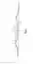
FIG. 1 is a sectional view of a preferred embodiment of the invention;
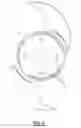
FIG. 2 is a plan view thereof; and
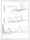
FIGS. 3-5 are diagrammatic views illustrating the operation of the invention.
DETAILED DESCRIPTION OF A PREFERRED EMBODIMENT OF THE INVENTIONA blade 30 designed for use in slicers includes a central, substantially planar securing zone 1 having a central opening 2 with an axis 9. This opening 2 serves for securing purposes in the case of a circular blade and for centering in the case of a scythe-like blade, with a plurality of securing openings 20 arranged distributed around the opening 2 with a radial spacing from the opening 2 being provided with such a scythe-like blade as shown in FIG. 2.
An exemplary scythe-like blade 30 is best shown in FIG. 2. The blade 30 includes an outer arcuate cutting edge 4 which performs the slicing cut of a food product upon rotation of the blade 30. Furthermore the entire cutting edge 4 lies in a base plane 6 (FIG. 1) which is perpendicular to the axis of rotation of the blade 30.
The central securing zone 1 merges radially outwardly through a transition region 8 into an arch 5 which forms a stabilizing zone. The arch 5, which is continuously curved in cross-section, surrounds the central securing zone 1 such that it lies in a depression in a practically recessed manner.
A marginal zone 3 radially outwardly adjoins the arch 5 and its periphery is made as a cutting edge 4. If, on the one hand, a base plane 6 is laid through the cutting edge 4 and a top plane 7 is laid through the apex of the arch 5, the central securing zone 1 is located between these two planes 6, 7, with the arch 5 and the inclination of the marginal zone 3 being selected with respect to the mentioned planes, which are parallel to one another such that, as a rule, the spacing of the central securing plane 1 is smaller with respect to the base plane 6 than with respect to the top plane 7.
The principle in accordance with the invention of the increase of the strength and stiffness of the blade with a simultaneous minimizing of the weight can be used both with blades whose cutting edge lies on a circle and with blades whose cutting edge extends in the manner of a scythe or over the periphery with an increasing radius.
With a ring-shaped arch 5 closed on itself, the scythe-like extent of the cutting edge can be achieved by a corresponding design of the marginal zone 3, but it is also possible to have the arch 5 follow the extent of the cutting edge over the periphery such that the marginal zone 3 also has a substantially similar radial extent over its periphery with a scythe-like blade.
As best shown in FIG. 1, the central securing zone 1 is spaced from the base plane of the cutting edge 4 by a distance greater than the material thickness of the blade 30. The central securing zone 1 is spaced from the top plane 7 so that the central securing zone is positioned between the top plane 7 and base plane 6. This construction provides several advantages.
First, this construction for the blade results in the center of gravity of the blade lying in substantially the same plane as the central securing zone 1. In practice aligning the center of gravity of the blade with the central securing 1 has been found to improve the cutting results for the slicing machine.
Secondly, and with reference to FIGS. 3-5, during a slicing operation the food product 40 is moved continuously toward the cutting blade 30 in the direction of arrow 42 from the position shown in FIG. 3 at the initiation of a slicing operation, through an intermediate cutting position shown in FIG. 4 and to the position shown in FIG. 5 at the end of the slicing operation. Consequently, by spacing the central securing zone 1 from the base plane 6 of the cutting blade, a collision or impact of the food product 40 against the central securing zone 1 at the end of the slicing operation is avoided as shown at 46 in FIG. 5.
Claims
1. A rotatingly drivable cutting blade, in particular for apparatuses working with a high cutting sequence for the slicing of food products,
comprising a substantially planar central securing zone (1) and an outer periphery serving as a cutting edge, with a stabilizing zone in the form of at least one circularly extending arch (5) being provided between the substantially planar central securing zone (1), which has at least one central opening (2), and a marginal zone (3) whose outer periphery is made as a cutting edge (4), said arch being continuously moved from the central securing zone and said marginal zone,
characterized in that
the arch (5) is formed in bead shape in cross-section and is continuously curved;
in that the cutting edge (4) is disposed in a base plane (6) forming the lower boundary of the cutting blade in the axial section of the cutting blade; and
in that the plane of the central securing zone (1), considered in the axial direction, is disposed between the base plane (6) and a top plane (7) extending through the apex of the continuously curved arch (5),
wherein the spacing of the central securing zone (1) from the base plane (6) and from the top plane (7) is in each case larger than the material thickness of the cutting blade to thereby prevent impact between the central securing zone and the food product during a slicing operation.
2. A cutting blade in accordance with claim 1, characterized in that the spacing of the central securing zone (1) from the base plane (6) is smaller than its spacing from the top plane (7).
3. A cutting blade in accordance with claim 1, characterized in that the marginal zone (3) extends toward the base plane (6) at an acute angle.
4. A cutting blade in accordance with claim 1, characterized in that the radial extent of the arch (5) approximately corresponds to the radial extent of the marginal zone (3).
5. A cutting blade in accordance with claim 1, characterized in that the outer periphery of the marginal zone (3) provided with the cutting edge (4) is circular.
6. A cutting blade in accordance with claim 1, characterized in that the arch (5) at least substantially follows the extent of the cutting edge in the peripheral direction of the blade with a cutting edge (4) extending in scythe-like shape.
7. A cutting blade in accordance with claim 1, characterized in that the arch (5) extends concentrically to the blade axis (9) with the cutting edge (4) extending in scythe-like shape.
8. A cutting blade in accordance with claim 6, characterized in that the central opening (2) forms a centering aperture; and in that securing openings are provided with a radial spacing from said centering aperture and are distributed around it.
9. A cutting blade in accordance with claim 7, characterized in that the central opening (2) forms a centering aperture; and in that securing openings are provided with a radial spacing from said centering aperture and are distributed around it.
Images & Drawings included:


Sources:
- United States Patent and Trademark Office - verify current appl. status at the USPTO↗
Similar patent applications:
- » 20050034587
Cutting blade that can be rotationally driven
Recent applications in this class:
- » 20250205915 2025-06-26
SLITTER HAVING SLITTER BODY AND DISC SEGMENTS - » 20250128443 2025-04-24
INDUSTRIAL KNIFE WITH A BASE BODY AND AN EXCHANGEABLE CUTTING EDGE PART - » 20250114960 2025-04-10
A CUTTING ASSEMBLY, A KNIFE FOR THE CUTTING ASSEMBLY, A COUNTER DEVICE FOR THE CUTTING ASSEMBLY, AND A METHOD OF SLICING FOOD WITH THE CUTTING ASSEMBLY - » 20250073936 2025-03-06
COMPOSITE BLADE SYSTEM - » 20240375306 2024-11-14
SYSTEM AND METHOD FOR COATING A BLADE - » 20240342939 2024-10-17
SLICING MACHINE FOR FOOD ARTICLES - » 20240316812 2024-09-26
Knife assembly with tab blades and method of fabrication - » 20240300128 2024-09-12
GEAR SLICING TOOL AND MANUFACTURE METHOD THEREOF - » 20240261994 2024-08-08
CRYSTAL CUTTING METHOD, METHOD OF MANUFACTURING SiC SEMICONDUCTOR DEVICE, AND SiC SEMICONDUCTOR DEVICE - » 20240100726 2024-03-28
Blade for Oscillating Power Tool
Recent applications for this Assignee:
- » 20070193425 2007-08-23
Slicing of food products - » 20060254402 2006-11-16
Cutting machine for food products - » 20060131133 2006-06-22
Transport apparatus with changeable angle between input and output streams - » 20060131133 2006-06-22
Transport apparatus with changeable angle between input and output streams - » 20050170056 2005-08-04
Method for the slicing of food products - » 20050132855 2005-06-23
Apparatus for the slicing of food products having two cutter heads - » 20050072322 2005-04-07
Device for slicing food products - » 10487193 2008-07-29
Distribution device