Acoustic material and method for making the same
US20070123676A1
2007-05-31
11/555,662
2006-11-01
✅ Patent granted
US 7,677,356 B2
2010-03-16
-
-
Edgardo San Martin
2028-06-20
Abstract:
An acoustic material includes at least a kind of synthetic staple fiber and a kind of low melting point fiber having a melting point lower than that of the at least one kind of synthetic staple fiber. Method for making the acoustic material includes the following steps: a) blending the synthetic staple fiber with the low melting point fiber together; b) cross lapping the mixed fibers to a predetermined thickness; c) drying the fibers to bond the fibers together.
Assignee:
- FOXCONN TECHNOLOGY CO., LTD. 1,179 🇹🇼 Tu-Cheng, Taiwan
- FOXCONN TECHNOLOGY CO., LTD. 537 🇹🇼 Tu-Cheng, Taipei Hsien, Taiwan
Interested in similar patents?
Get notified when new applications in this technology area are published.
Classification:
D04H1/74 » CPC main
Non-woven fabrics formed wholly or mainly of staple fibres or like relatively short fibres characterised by the method of forming fleeces or layers, e.g. reorientation of fibres the fibres being orientated, e.g. in parallel (anisotropic fleeces)
D04H1/435 » CPC further
Non-woven fabrics formed wholly or mainly of staple fibres or like relatively short fibres from fleeces or layers composed of fibres without existing or potential cohesive properties characterised by the use of certain kinds of fibres insofar as this use has no preponderant influence on the consolidation of the fleece; Condensation or reaction polymers Polyesters
D04H1/46 » CPC further
Non-woven fabrics formed wholly or mainly of staple fibres or like relatively short fibres from fleeces or layers composed of fibres without existing or potential cohesive properties the fleeces or layers being consolidated by mechanical means, e.g. by rolling by needling or like operations to cause entanglement of fibres
D04H1/48 » CPC further
Non-woven fabrics formed wholly or mainly of staple fibres or like relatively short fibres from fleeces or layers composed of fibres without existing or potential cohesive properties the fleeces or layers being consolidated by mechanical means, e.g. by rolling by needling or like operations to cause entanglement of fibres in combination with at least one other method of consolidation
D04H1/54 » CPC further
Non-woven fabrics formed wholly or mainly of staple fibres or like relatively short fibres from fleeces or layers composed of fibres without existing or potential cohesive properties by welding together the fibres, e.g. by partially melting or dissolving
D04H1/5418 » CPC further
Non-woven fabrics formed wholly or mainly of staple fibres or like relatively short fibres from fleeces or layers composed of fibres without existing or potential cohesive properties by welding together the fibres, e.g. by partially melting or dissolving; Composite fibres, e.g. sheath-core, sea-island or side-by-side; Mixed fibres Mixed fibres, e.g. at least two chemically different fibres or fibre blends
D04H1/544 » CPC further
Non-woven fabrics formed wholly or mainly of staple fibres or like relatively short fibres from fleeces or layers composed of fibres without existing or potential cohesive properties by welding together the fibres, e.g. by partially melting or dissolving; Adhesive fibres Olefin series
D04H1/55 » CPC further
Non-woven fabrics formed wholly or mainly of staple fibres or like relatively short fibres from fleeces or layers composed of fibres without existing or potential cohesive properties by welding together the fibres, e.g. by partially melting or dissolving; Adhesive fibres Polyesters
H04R31/003 » CPC further
Apparatus or processes specially adapted for the manufacture of transducers or diaphragms therefor for diaphragms or their outer suspension
H04R2307/025 » CPC further
Details of diaphragms or cones for electromechanical transducers, their suspension or their manufacture covered by or , not provided for in any of its subgroups Diaphragms comprising polymeric materials
H04R2307/029 » CPC further
Details of diaphragms or cones for electromechanical transducers, their suspension or their manufacture covered by or , not provided for in any of its subgroups Diaphragms comprising fibres
C08F10/00 IPC
Homopolymers and copolymers
C08F10/00 IPC
Homopolymers and copolymers of unsaturated aliphatic hydrocarbons having only one carbon-to-carbon double bond
H04R7/10 IPC
Diaphragms for electromechanical transducers ; Cones characterised by the construction; Plane diaphragms comprising a plurality of sections or layers comprising superposed layers in contact
H04R7/06 IPC
Diaphragms for electromechanical transducers ; Cones characterised by the construction; Plane diaphragms comprising a plurality of sections or layers
G10K13/00 IPC
Cones, diaphragms, or the like, for emitting or receiving sound in general
H04R7/02 IPC
Diaphragms for electromechanical transducers ; Cones characterised by the construction
Description
BACKGROUND OF THE INVENTION1. Field of the Invention
The present invention relates generally to an acoustic material employed as a diaphragm of an electroacoustic device, and more particularly to a method for manufacturing the acoustic material.
2. Description of Related Art
Sound is one important means by which people communicate with each other, thus creating new methods for sound transference allows greater communication between people. Electroacoustic transducers are key components in transferring sound. A typical electroacoustic transducer has a magnetic circuit in which a magnetic field generated by a magnet passes through a base member, a magnetic core and a diaphragm and returns to the magnet again. When an oscillating electric current is supplied to a coil wound around the magnetic core, the corresponding oscillating magnetic field generated by the coil is then superimposed onto the static magnetic field of the magnetic circuit. The resulting oscillation generated in the diaphragm is then transmitted to the air as sound. The basic loudspeaker, in which electric energy is converted to acoustic energy, is a typical electroacoustic transducer. There are many different types of loudspeakers, including electrostatic loudspeakers, piezoelectric loudspeakers, and moving-coil loudspeakers.
Nowadays, mobile phones are widely used and loudspeakers are important components packaged within mobile phones. As design style for mobile phones emphasizes lightness, smallness, energy-efficiency, low cost, the space available for loudspeakers within mobile phones is therefore limited. Furthermore, as more and more mobile phones are being used to play MP3s, the rated power of the loudspeakers needs to increase. The space occupied by loudspeakers mainly depends on maximum deformation displacement of a diaphragm of the loudspeaker.
Therefore, it is desired to design a new diaphragm for micro-electroacoustic transducers having low density and high modulus of elasticity, thus enhancing the reproduction frequency range.
SUMMARY OF THE INVENTIONAccording to a preferred embodiment of the present invention, an acoustic material which can be employed as a diaphragm of an electroacoustic device includes at least one kind of synthetic staple fiber and a kind of low melting point fiber having a melting point lower than that of the at least one kind of synthetic staple fiber. Method for making the acoustic material includes the following steps: a) blending the at least one synthetic staple fiber with the low melting point fiber together; b) cross lapping the mixed fibers to a predetermined thickness; c) drying the fibers to bond the fibers together.
Other advantages and novel features of the present invention will become more apparent from the following detailed description of preferred embodiment when taken in conjunction with the accompanying drawings, in which:
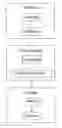
BRIEF DESCRIPTION OF THE DRAWINGSFIG. 1 is a flow chart of a preferred method in accordance with the present invention, for manufacturing an acoustic material applicably employed as a diaphragm of an electroacoustic device;
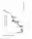
FIG. 2 is a graph indicating relation between a flow resistance and a density of the acoustic material;
FIG. 3 is a graph indicating real impedances of the present acoustic material and a related acoustic material;
FIG. 4 is similar to FIG. 3, but shows simulated impedances of the two acoustic materials; and
FIG. 5 is a graph indicating sound absorption coefficients of the present acoustic material and a related acoustic material.
DETAILED DESCRIPTION OF THE INVENTIONFIG. 1 shows a preferred method in accordance with the present invention for producing an acoustic material which can be employed as a diaphragm of an electroacoustic device, such as a loudspeaker. The acoustic material is obtained by several kinds of fibers mixed together, and a plurality of processes is required to bond the fibers together to form the acoustic material.
The acoustic material includes at least one kind of synthetic staple fiber, and a kind of low melting point fiber. The melting point of the low melting point fiber is lower than that of the synthetic staple fiber. For enhancing the surface finish of the acoustic material and the convenience for producing of the acoustic material, a little of superfine fiber which is not larger than 0.3 fiber number can be added to the acoustic material. The “fiber number” used herein represents a size of the fiber. An average diameter of the fiber of 0.3 fiber number is about 0.5 μm. Alternatively, non-woven fiber or flame retardant superfine fiber can be added to the acoustic material to enhance the surface finish of the acoustic material. The synthetic staple fiber is used to absorb energy of the sound. The synthetic staple fiber is synthetic polyester fiber. The low melting point fiber is used to bond the fibers together, and may be selected from Polyethylene (PE), polyethylene terephthalate (PET), polypropylene (PP) or the like. An average diameter of the low melting point fiber is in range of 1 μm to 50 μm. The synthetic staple fiber and the low melting point fiber are greater than the superfine fiber in diameter. Each kind of the fibers has an average diameter different from that of the other fibers to enhance a range of the frequency of the sound absorbed by the acoustic material.
As shown in FIG. 1, firstly a fiber blending process is used to mix the fibers which are required for producing the acoustic material together. In this embodiment, the acoustic material is made from a kind of synthetic staple fiber, a kind of low melting point fiber and a kind of superfine fiber. The three kinds of fibers are synthetic polyester fiber. An average diameter of the synthetic staple fiber is about 9.1 μm, and an average diameter of the low melting point fiber is about 14.4 μm. A ratio of the synthetic staple fiber to the acoustic material is in range of 65˜95% in weight. A ratio of the low melting point fiber to the acoustic material is in range of 5˜35% in weight, and a ratio of the superfine fiber to the acoustic material is in range of 0˜0.1% in weight.
The blending process includes a fiber opening step and a fiber carding step. The three kinds of fibers are evenly dispersed and distributed during the opening process. The carding process blends the fibers thoroughly throughout. Thus the three kinds of fibers of different sizes and textures are blended complete, and are lamellar-shaped. Then cross lapping process is used to laminate the fibers to a predetermined thickness. The lamellar-shaped fibers are laminated to the predetermined thickness and then sewed together using a needle punching step. Thus the fibers are laminated to the predetermined thickness and are fixed together. Finally the fibers are put through a drying process to bond themselves together. Firstly, the fibers are heated under a temperature in a range from 100˜200° C. for 5 seconds to 40 minutes. The low melting point fiber intenerates to agglutinate the fibers together. The temperature and time for heating the fibers is determined by the thickness of the fibers. The thickness of the fibers is larger, the temperature needed is higher, and the time needed for the drying process is longer. Then cooling the fibers under the ambient temperature for 5 seconds to 40 minutes to obtain the acoustic material. For enhancing the surface finish, a cooling calendaring or hot calendaring process can be applied to the acoustic material. In the drying process, a little of non-woven fiber or flame retardant fiber, is added for enhancing the surface finish of the acoustic material and the convenience of producing the acoustic material.
The present acoustic material is obtained by several different kinds of fibers bonding together. Each kind fiber has a reproduction frequency range different from that of the others for the different size thereof. Thus the reproduction frequency range of the acoustic material is widened. The acoustic material can be constructed in different thicknesses, sizes, shapes, etc. Also a density of the acoustic material can be changed by changing the content or the sort of the fibers in the acoustic material. For satisfying lightless requirement of the electroacoustic device, a preferred density of the acoustic material is in range of 1˜250 kg/m3. FIG. 2 shows flow resistances of the acoustic materials of different densities. The thicknesses of the acoustic materials are the same which are about 10 mm. The flow resistance of the acoustic material having a density about 32.5 kg/m3 is about 33 KNs/m4. The flow resistance of the acoustic material increases with the density of the acoustic materials. Acoustic materials having densities of 43.3, 52, 65, 98 and 130 kg/m3 have flow resistances of 38, 53, 70, 116 and 162 KNs/m4, respectively.
FIGS. 3-4 show impedances of a present acoustic material and a related acoustic material. FIG. 3 shows real parts of the impedances, and FIG. 4 shows imaginary parts of the impedances of the acoustic materials. The impedances of the two materials are similar to each other. A thickness of each of the two materials is about 10 mm. However, a density of the related acoustic material is about 210 kg/m3, whilst a density of the present acoustic material is much smaller than that of the related acoustic material, which is just about 98 kg/m3. FIG. 5 shows sound absorption coefficients of the present acoustic material and the related acoustic material. The sound absorption coefficient of the present acoustic material is a little larger than that of the related acoustic material. Thus the present acoustic material has a weight much smaller than the related acoustic material, but has the same sound absorption coefficient and impedance as the related acoustic material. A diaphragm for electroacoustic transducers made of the present acoustic material has low density and high modulus of elasticity, and hence enhancing the reproduction frequency range of the micro-electroacoustic devices.
It is to be understood, however, that even though numerous characteristics and advantages of the present invention have been set forth in the foregoing description, together with details of the structure and function of the invention, the disclosure is illustrative only, and changes may be made in detail, especially in matters of shape, size, and arrangement of parts within the principles of the invention to the full extent indicated by the broad general meaning of the terms in which the appended claims are expressed.
Claims
What is claimed is:1. An acoustic material for being employed as a diaphragm of an electroacoustic device, comprising:
at least one kind of synthetic staple fiber; and
a kind of low melting point fiber having a melting point lower than that of the at least one kind of synthetic staple fiber.
2. The acoustic material of claim 1, wherein a ratio of the at least one kind of synthetic staple fiber to the acoustic material is in range of 65˜95% in weight, and a ratio of the low melting point fiber to the acoustic material is in range of 5˜35% in weight.
3. The acoustic material of claim 1, wherein the low melting point fiber and the at least one kind of synthetic staple fiber are synthetic polyester fiber.
4. The acoustic material of claim 3, wherein the low melting point fiber is selected from one of the following materials: Polyethylene, polyethylene terephthalate and polypropylene.
5. The acoustic material of claim 1, wherein an average diameter of the low melting point fiber is in a range of 1˜50 μm.
6. The acoustic material of claim 1, further comprising one of the following materials: superfine fiber, non-woven fiber and flame retardant fiber, which has a ratio of 0˜0.1% to the acoustic material in weight and an average diameter not larger than 0.5 μm.
7. The acoustic material of claim 1, wherein the acoustic material has a density in range of 1˜250 kg/m3.
8. A method for making an acoustic material for use as a diaphragm of an electroacoustic device comprising the following steps:
providing at least one kind of synthetic staple fiber and a kind of low melting point fiber having a melting point lower than that of the at least one kind of synthetic staple fiber;
blending the fibers together;
cross lapping the mixed fibers to a predetermined thickness; and
drying the fibers to bond the fibers together.
9. The method of claim 8, wherein the blending process comprises a fiber opening step and a fiber carding step.
10. The method of claim 8, wherein the cross lapping process comprises a laminated step and a needle punching step.
11. The method of claim 8, wherein the drying process comprises a heating step and a cooling step.
12. The method of claim 11, wherein the heating step is under a temperature in range of 100˜200° C. for 5 seconds to 40 minutes, and the cooling step is under ambient temperature for 5 seconds to 40 minutes.
13. The method of claim 8, wherein during the drying process one of the following materials: superfine fiber, non-woven fiber and flame retardant fiber, which has a ratio of 0˜0.1% to the acoustic material in weight and an average diameter not larger than 0.5 μm, is added to the acoustic material.
14. The method of claim 8, wherein a ratio of the at least one kind of synthetic staple fiber to the acoustic material is in range of 65˜95% in weight, and a ratio of the low melting point fiber to the acoustic material is in range of 5˜35% in weight.
Images & Drawings included:


Sources:
- United States Patent and Trademark Office - verify current appl. status at the USPTO↗
Similar patent applications:
- » 20240355312
BIODEGRADABLE ACOUSTIC ATTENUATING MATERIAL AND METHOD OF MAKING SAME - » 20100090153
Fiber-based acoustic treatment material and methods of making the same - » 20110296794
Acoustical sound proofing materials and methods of making the same - » 20140050902
Acoustical sound proofing materials and methods of making the same - » 20100196686
POROUS FACING MATERIAL, ACOUSTICALLY ATTENUATING COMPOSITE, AND METHODS OF MAKING AND USING THE SAME - » 20200037064
Passive acoustic meta material audio amplifier and the method to make the same - » 20180359558
Passive acoustic meta material audio amplifier and the method to make the same - » 20200213721
Passive acoustic meta material audio amplifier and the method to make the same - » 20090163115
METHOD OF MAKING ACOUSTIC HOLES USING UV CURING MASKING MATERIAL - » 10065813
Method for making electrical connection to ultrasonic transducer through acoustic backing material
Recent applications in this class:
- » 20250179703 2025-06-05
Nonwoven Material with Three-Dimensional Active Wicking and Evaporation - » 20240301601 2024-09-12
NON-WOVEN MICRO-TRELLIS FABRICS AND COMPOSITE OR HYBRID-COMPOSITE MATERIALS REINFORCED THEREWITH - » 20240263372 2024-08-08
CARBON FIBER NONWOVEN FABRIC SHEET, METHOD FOR PRODUCING SAME AND CARBON FIBER REINFORCED RESIN MOLDED BODY USING SAME - » 20240191409 2024-06-13
RECYCLABLE LINER, PANEL, OR COMPONENT - » 20230050800 2023-02-16
HIGH-STRENGTH PROTECTIVE CLOTH WITH MOISTURE PERMEABILITY AND MANUFACTURING METHOD THEREOF - » 20220162787 2022-05-26
METHOD FOR NONWOVEN TEXTILES WITH VARIABLE ZONAL PROPERTIES - » 20220162786 2022-05-26
Nonwovens having aligned segmented fibers - » 20220042224 2022-02-10
Fabrication of nanofibers as dry adhesives and applications of the same - » 20210388549 2021-12-16
FIBER STRUCTURE - » 20210285138 2021-09-16
FIBER MESH SHEET, METHOD FOR MANUFACTURING FIBER MESH SHEET, AND CELL CULTURE CHIP FORMED OF FIBER MESH SHEET
Recent applications for this Assignee:
- » 20140060781 2014-03-06
HEAT PIPE AND METHOD FOR MANUFACTUREING THE SAME - » 20140030075 2014-01-30
Housing of cooling fan and method manufacturing of the same - » 20140000855 2014-01-02
Heat dissipation device with fastener - » 20130343003 2013-12-26
Heat dissipation device with fastener and flange - » 20130342994 2013-12-26
Electronic device having fixing member - » 20130340973 2013-12-26
Heat dissipation device with fastener - » 20130323344 2013-12-05
Injection molding apparatus having a thermostat assembly - » 20130312938 2013-11-28
HEAT PIPE WITH VAPORIZED WORKING FLUID FLOW ACCELERATOR - » 20130309094 2013-11-21
Cooling fan with impeller - » 20130306294 2013-11-21
HEAT DISSIPATION DEVICE WITH FASTENER