Orthodontic bone anchor
US20070123882A1
2007-05-31
11/268,053
2005-11-08
✅ Patent granted
US 7,850,450 B2
2010-12-14
-
-
Cris L Rodriguez | Heidi M Eide
2027-02-10
Abstract:
An orthodontic bone anchor comprising an anchor plate, a tube affixed to the emerging end of the anchor plate and, a rod slidable within the tube, a groove formed in the rod, a plate attached to the tube at one end and having a V-shaped notch at the other end, and the V-shaped notch adapted to cooperate with the groove to prevent movement of the rod with respect to the tube.
Interested in similar patents?
Get notified when new applications in this technology area are published.
Classification:
A61C7/00 » CPC main
Orthodontics, i.e. obtaining or maintaining the desired position of teeth, e.g. by straightening, evening, regulating, separating, or by correcting malocclusions
A61C7/22 » CPC further
Orthodontics, i.e. obtaining or maintaining the desired position of teeth, e.g. by straightening, evening, regulating, separating, or by correcting malocclusions; Brackets; Arch wires; Combinations thereof; Accessories therefor; Arch wires Tension adjusting means
A61C7/282 » CPC further
Orthodontics, i.e. obtaining or maintaining the desired position of teeth, e.g. by straightening, evening, regulating, separating, or by correcting malocclusions; Brackets; Arch wires; Combinations thereof; Accessories therefor; Securing arch wire to bracket Buccal tubes
A61C8/0096 » CPC further
Means to be fixed to the jaw-bone for consolidating natural teeth or for fixing dental prostheses thereon; Dental implants; Implanting tools; Features of implants not otherwise provided for Implants for use in orthodontic treatment
A61F2/30 IPC
Filters implantable into blood vessels; Prostheses, i.e. artificial substitutes or replacements for parts of the body; Appliances for connecting them with the body; Devices providing patency to, or preventing collapsing of, tubular structures of the body, e.g. stents; Prostheses implantable into the body Joints
A61C3/00 IPC
Dental tools or instruments
Description
BACKGROUND OF THE INVENTIONIn orthodontics, typically an anchor plate is screwed to a patient's bone and extends into the vestibule from which elastomeric material or springs are attached to facilitate movement of the patient's teeth. The disadvantage to this is that the point of force application cannot be changed during treatment nor can the bone anchor be modified or adjusted prior to insertion or during treatment. A change in the location of force application to the dentition is often required and without a corresponding change on the anchor, a different and generally undesirable change in the vector of force occurs. In addition, the surgeon often encounters difficulty in placing the anchor plate as distally as desired.
SUMMARY OF THE INVENTIONAn anchor plate is secured to a patient's bone with an angular tube secured to the emerging end thereof, a corresponding angular rod is inserted through the tube and multiple grooves are formed in the rod. In addition, a plate is adhered to the tube at one end thereof and is adapted to flex either vertically or horizontally depending on where the plate is placed. A V-shaped notch is formed on the distal end of the plate and adapted to cooperate with the grooves formed in the rod and allow the rod to be incrementally extended with respect to the tube.
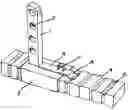
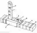
DESCRIPTION OF THE DRAWINGThe single view drawing is a perspective view of the orthodontic bone anchor according to this invention.
DETAILED DESCRIPTION OF THE INVENTIONIn the drawing, anchor plate 1 is shown which is attached to a patient's bone by means of screws inserted through apertures 2. Quadrilateral tube 3 is secured to the emerging end of anchor plate 1 by any suitable means such as welding and quadrilateral rod 4 is insertable through hollow tube 3, as shown in the drawing. In addition, multiple grooves 5 extend around the periphery of rod 4.
According to a feature of this invention, resilient plate 6 is attached to the outer surface of tube 3 adjacent anchor plate 1 by suitable means such as welding and the like. Also, loop or hook 7 is attached to the upper surface of plate 6 by means such as welding. Finally, a V-shaped notch 8 is formed on the free end of plate 6 and is adapted to cooperate with grooves 5.
In practice, anchor plate 1 is secured to a patient's bone by means of screws inserted through apertures 2 as is well known. Then, depending on the desired location and direction of the force vector, plate 6 is lifted by grasping loop 7 by means of an appropriate instrument and lifting plate 6 such that rod 4 is maneuverable through tube 3 to the desired position as determined by the clinician. Loop 7 is then released and plate 6 springs downwardly so as to allow V-shaped notch 8 to nest with whichever one of the grooves 5 is disposed therebelow. By this means, rod 4 is, in effect, locked in place. Following this, appropriate elastomeric material or springs are placed around the appropriate groove 5 for optimum force application.
As an alternative, anchor plate 1 can be bent through an arc of 90 degrees so as to achieve an alternative disposition of rod 4 depending on the force requirements of the particular patient.
Therefore, by this invention, a bone anchor is provided which is adjustable to allow multiple points of vertical force application from a single bone anchor without the necessity of multiple bone anchors, the need to move the anchor from one location to another, and with lessened demand on the part of the surgeon to place the bone anchor in a precise location.
Claims
1. An orthodontic bone anchor comprising an anchor plate, a hollow angular tube affixed to one end thereof, an angular rod slidable within said tube, and at least one groove formed in said rod.
2. An orthodontic bone anchor according to claim 1 wherein said groove extends around the periphery of said rod.
3. An orthodontic bone anchor according to claim 1 wherein a plate is resiliently affixed at one end thereof to said tube.
4. An orthodontic bone anchor according to claim 3 wherein a notch is formed on the free end of said plate.
5. An orthodontic bone anchor according to claim 4 wherein a loop or hook is affixed to the surface of said plate opposite said tube.
6. An orthodontic bone anchor according to claim 5 wherein said plate is attached to said tube adjacent to said anchor plate.
Images & Drawings included:
Sources:
- United States Patent and Trademark Office - verify current appl. status at the USPTO↗
Similar patent applications:
- » 20050147938
Orthodontic bone anchor - » 20110008745
ORTHODONTIC BONE ANCHOR PLATE WITH MESH PAD
Recent applications in this class:
- » 20250152302 2025-05-15
ORTHODONTIC PROGRESS TRACKING USING COARSE TO FINE 3D MODELS - » 20250049537 2025-02-13
SYSTEMS AND METHODS FOR ORTHODONTIC TREATMENT PROGRESS TRACKING - » 20250017691 2025-01-16
PALATAL ANCHORAGE DEVICE FOR ORTHODONTIC TREATMENT WITH ENHANCED SUPPORT AND METHOD MANUFACTURING PALATAL ANCHORAGE DEVICE - » 20240268927 2024-08-15
BASE MATERIAL FOR SCREW, SCREW, AND METHOD FOR PRODUCING SAME - » 20240058098 2024-02-22
Magnetic-field-adjustable micromagnetic orthodontic accelerator - » 20240024073 2024-01-25
Systems and methods for orthodontic treatment progress tracking - » 20230181285 2023-06-15
Treatment progress tracking and recalibration - » 20230000593 2023-01-05
METHODS FOR PROGRESS TRACKING - » 20210338378 2021-11-04
Device for moving a tooth or group of teeth - » 20210177545 2021-06-17
Mobile orthodontic treatment system and method